Note: Descriptions are shown in the official language in which they were submitted.
r
CA 02393633 2002-07-17
Innovance Inc
Privileged and Confidential
Docket #1010CA
METHOD FOR ENGINEERING CONNECTIONS IN A DYNAMICALLY
RECONFIGURABLE PHOTONIC SWITCHED NETWORK
Priority Patent Applications
Provisional US Patent Application "Method for Engineering Connections in
a Dynamically Reconfigurable Photonic Switched Network" (Zhou et al.) SN
60/306,302, docket 1010P.
Field of the invention
The invention is directed to a telecommunication network, and in particular
to a method for engineering connections in a dynamically reconfigurable
photonic
network.
Background of the invention
Current transport networks are based on a WDM (wavelength division
multiplexing) physical layer, using point-to-point (pt-pt) connectivity. A WDM
optical signal comprises a plurality of transmission channels, each channel
carrying an information (data) signal modulated over a carrier wavelength.
The span reach, or the distance between a transmitter and the next
receiver, is limited by the combined effect of attenuation and distortion
experienced by the signal along the optical fiber. A solution to increase the
span
reach is to place optical amplifiers between the nodes. While the amplifiers
significantly increase the optical power of all optical channels passing
through
them, they exhibit a wavelength-dependent gain profile, noise profile, and
saturation characteristics. Hence, each optical channel experiences a
different
gain along a transmission path. The optical amplifiers also add noise to the
signal, typically in the form of amplified spontaneous emission (ASE), so that
the
optical signal-to-noise ratio (OSNR) decreases at each amplifier site.
1
CA 02393633 2002-07-17
Furthermore, the optical signals in the co-propagating channels have different
initial waveform distortions and undergo different additional distortions
during
propagation along the transmission medium (optical fiber). As a result, the
signals have different power levels, OSNRs, and degrees of distortion when
they
arrive at the respective receivers, if they had equal power levels at the
corresponding transmitters.
As the flexibility of today's networks is delivered electronically,
termination
of photonic layer is necessary at each intermediate node along a route, and
therefore optimization can be performed by equalizing the system span by span.
There are numerous performance optimization methods applicable to traditional
networks, all based on 'equalizing' a certain transmission parameter of the
WDM
signal. It has been shown that the SNR (signal-to-noise ratio) at the output
of an
amplified WDM system can be equalized by adjusting the input optical power for
all channels. For example, U.S. Pat. No. 5,225,922 (Chraplyvy et al.), issued
on
July 6, 1993 to AT&T Bell Laboratories, provides for measuring the output SNRs
and then iteratively adjusting the input powers to achieve equal SNRs. A
telemetry path between the nodes provides the measurements obtained at one
node to the other.
Performance of an optical system is also defined by the BER (bit error
rate) and Q factor. BER is the ratio between the number of the erroneously
received bits to the total number of bits received over a period of time. US
Patent No 6,115,157 (Bamard et al.) issued to Nortel Networks Corporation on
September 5, 2000 discloses a method of equalizing the channels of a WDM
path based on an error threshold level for each channel in the WDM signal, set
in
accordance with the channel rate. The transmitter power is adjusted taking
into
account the attenuations determined for all channels, which attenuations are
calculated according to the measured BER.
As indicated above, these traditional span engineering methods are
applicable to point-to-point network architectures, where all channels of a
WDM
signal co-propagate along the same physical medium (fiber strand) and between
same source and destination nodes.
The present invention is applicable to a photonic network where each
signal travels between a different source and destination node without
unnecessary OEO conversions at all intermediate nodes. Thus, the conventional
pt-pt based DWDM transport boundaries disappear in this architecture and are
replaced by individual wavelength channels going on-ramp and off ramp at
2
CA 02393633 2002-07-17
arbitrary network nodes. Details about the architecture and operation of this
photonic network are provided in the above identified priority patent
applications
docket 1001 and 1021.
By removing OEO conversion for the passthru channels at the switching
nodes, connection set-up and control become significant physical design
challenges. Traditional channel performance optimization methods do not apply
to end-to-end connections that pass through many nodes without OEO
conversion. Furthermore, traditional section-by-section equalization cannot be
performed; connections sharing a given fiber section now have substantially
different noise and distortion impairments, determined by their network
traversing
history.
There is a need to provide a method for engineering connections in
photonic switched networks, where the channels do not have the same source
and destination node.
Traditional point-to-point WDM nefinrorks perform span and path
engineering based on the worst-case rules, in that the channels are aligned to
the performance of the weakest channel. This clearly is not the most
advantageous way of using the network resources.
There is a need to provide a method for engineering connections, which
makes a better use of the available network resources than the current
equalization methods.
Furthermore, traditional networks are static, in that channel allocation is
fixed and any addition or removal of a channel implies extensive engineering
of
all channels along the affected section(s). On the other hand, the photonic
switched network to which this invention applies is provided with a routing
and
switching mechanism that allows automatic set-up and tear-down of connections
or on request. Clearly, the traditional span and path equalization methods
cannot be applied in the context of dynamical reconfiguration of connections
as
in the above-referred photonic switched network.
There is a need to provide a method of engineering connections by
switching a connection from a current path to another or changing the
configuration of the current path automatically, once the network detects that
the
performance parameters of the current path are below preset thresholds.
Summary of the invention
3
CA 02393633 2002-07-17
It is an object of the invention to provide a method for engineering
connections in a dynamically reconfigurable photonic switched network.
The present invention is aimed at optimizing performance and cost of a
D/WDM photonic network and ensuring a connection performance level over the
lifetime of a given network connection, in the presence of network
reconfiguration
and other churn in the physical layer.
Accordingly, the invention is directed to a WDM network for routing a channel
from an input node to an output node through an intermediate switching node
connected along a transmission path, comprising: at the input node, means for
multiplexing the channel into a first multi-channel optical signal and
transmitting
the first multi-channel optical signal over the path; at the intermediate
node, a
wavelength switching subsystem WSS for routing the channel from the first
multi-
channel optical signal into a second multi-channel optical signal without OEO
conversion, and transmitting the second multi-channel optical signal over the
path; and at the output node, means for demultiplexing the channel from the
second multi-channel optical signal.
According to one aspect, the invention provides a node of a WDM network
comprising: an input port for receiving a first multi-channel optical signal,
and an
output port for transmitting a second multi-channel optical signal; a
broadband
optical receiving terminal for receiving a drop channel and recovering a drop
user
signal from the drop channel; a drop tree for broadcasting the first multi-
channel
optical signal over a plurality of drop routes, selecting a drop route and
routing
the drop channel from the input port to the broadband optical receiving
terminal;
and a wavelength switching subsystem WSS for routing a passthru channel from
the first multi-channel optical signal into the second multi-channel optical
signal,
in optical format.
Still further, a method of routing a communication channel from an input
node to an output node through an intermediate switching node connected along
a path is also introduced by this invention. the method comprises: at the
input
node, multiplexing the channel into a first multi-channel optical signal and
transmitting the first multi-channel optical signal to the intermediate node;
at the
intermediate node, switching the channel from the first multi-channel optical
signal into a second multi-channel optical signal without OEO conversion, and
transmitting the second multi-channel optical signal to the output node; at
the
output node, demultiplexing the channel from the second multi-channel optical
signal; and controlling operation of the input node, the output node and the
4
CA 02393633 2002-07-17
intermediate node at the physical layer using a smart line system SLS and at
the
network layer using an intelligent network operating system INOS.
According to another aspect of the invention, there is also provided a
method for engineering of a connection in a WDM photonic network with a
plurality of flexibility sites connected by links, comprising: (a) calculating
a
physical end-to-end route between a source node and a destination node; (b)
setting-up a data communication path along the end-to-end route; (c) testing
an
operational parameter of the data communication path; and (d) comparing the
operational parameter with a margin tolerance and declaring the data
communication path as established, whenever the operational parameter is
above the margin tolerance.
Another aspect of the invention concerns a data communication path for
connecting a source node with a destination node along one or more
intermediate nodes of a photonic network, the data communication path
operating in one of a monitoring mode and a maintenance mode, according to a
path operational parameter.
Still another aspect of the invention provides a photonic network for
routing a data communication path between a source node and a destination
node along a route passing through an intermediate node, comprising: a pool of
wavelength-converter/regenerators connected at the intermediate node; a line
control system for collecting performance information on the data
communication
path; and a network management system for assigning a wavelength-converter/
regenerator from the pool to the data communication path and switching the
data
communication path through the wavelength-converter/regenerator, whenever
the performance of the data communication path is outside an operation range.
A method of engineering a connection between two terminals of a
dynamically reconfigurable photonic network comprises, according to still
another
aspect of the invention: setting-up a path whenever an operational parameter
of
the path is above a test threshold; operating the path in monitoring mode
whenever the operational parameter is above a maintenance threshold; and
servicing the path whenever the operational parameter is under the maintenance
threshold.
The invention is also directed to a method of engineering a connection
over a WDM photonic network with a plurality of flexibility sites, comprising:
selecting a data communication path for the connection based on network
topology information, resources specifications and class of service
constrains;
5
CA 02393633 2002-07-17
turning on a source transmitter, a destination receiver and all transmitters
and
receivers at all flexibility sites along the path; increasing gradually the
power level
of the transmitters while measuring an error quantifier at the destination
receiver;
and maintaining the power at the transmitters at a first level corresponding
to a
preset error quantifier.
According to a still further aspect, the invention provides for a control
system for engineering connections in a photonic switched network, with a
plurality of wavelength cross-connects WXC connected by links comprising: a
plurality of control loops, each for monitoring and controlling a group of
optical
devices, according to a set of loop rules; a plurality of optical link
controllers,
each for monitoring and controlling operation of the control loops provided
along
a link; a plurality of optical vertex controllers, each for monitoring and
controlling
operation of the control loops provided at a wavelength cross-connect; and a
network connection controller for constructing a data communication path
within
the photonic switched network and for monitoring and controlling operation of
the
optical link controller and the optical vertex controller.
By moving away from the traditional worst case based engineering rules
the overall network design and cost can be significantly optimized.
Advantageously, the invention provides end-to-end path performance
optimization based on current network connectivity information and current
physical performance parameters of the path, which leads to significant up-
front
and lifecycle network cost savings.
Use of current network connectivity information and current physical
performance parameters of the path also confers better accuracy of network
operations control.
Furthermore, the path engineering method according to the invention
provides for flexibility of control. Thus, in one embodiment, a path switch or
a
path configuration change is prompted based on real-time network performance
parameters, on cost and churn tolerance and network loading. In another
embodiment, a path switch or a path configuration change is triggered whenever
a path operates outside a flexibly allocated Q range. This reduces the
complexity of traditional engineering methods, resulting in a network that can
be
exploited based on class of service specific constrains.
Still further, the engineering method according to the invention provided
for an adaptive power turn-on procedure that allows significant savings, as
the
6
CA 02393633 2002-07-17
path power is set according to the current performance, rather than according
to
the possible end-to-end performance as in traditional procedures. The power
setting can be moved up as the network ages, the local conditions change, etc.
Brief description of the drawings
The foregoing and other objects, features and advantages of the invention
will be apparent from the following more particular description of the
preferred
embodiments, as illustrated in the appended drawings, where:
Figure 1A shows the general architecture for a photonic network
according to one embodiment of the invention;
Figure 1 B shows a block diagram of the network operating system of
network shown in Figure 1A;
Figure 2A shows a flow chart of the testing, margin hedging, monitoring
and churn management TMMCM procedure according to an embodiment of the
invention;
Figure 2B shows a state machine for individual end-end path states
based on TMMCM procedure;
Figure 3 is a flow chart a path engineering procedure according to
another embodiment of the invention;
Figure 4 is a block diagram of the line control system of network of Figure
1 A;
Figure 5A shows the flow of information between the optical devices, the
line control system and the network operating system;
Figure 5B shows a control loop and stimulus propagation;
Figure 5C illustrates how a control signal stimulates a network of control
loops;
Figure 6A shows a gain loop; and
Figure 6B shows a vector loop.
Description of preferred embodiments
The term 'connection' refers here to an end-to-end logical path, which can
be set-up along a plurality of physical paths, using regenerators at
intermediate
nodes as/if needed, and employing one or more wavelengths.
The term 'flexibility site' or 'flexibility point' refers to a node of a
D/V11DM
network where connections could be added, dropped and/or switched from an
input fiber to an output fiber. Such nodes are provided in the network
according
7
CA 02393633 2002-07-17
to the above-identified patent applications with a wavelength cross-connect or
with an optical add/drop multiplexer.
The term 'path' refers here to a source-destination physical route (also
referred to as an 'A-Z path' or A-Z connection). A path can have one or more
configurations, due to the flexible regenerator placement and wavelength
assignment capabilities. The term 'link' is used for the portion of the
nefinrork
between two flexibility sites, and the term 'section' refers to the portion of
the
network between two optical amplifiers. The term 'channel' is used to define a
carrier signal of a certain wavelength modulated with an information signal.
The term 'reconfiguration' in the context of a photonic network as
described below refers to the ability of the network to add, remove,
reconfigure
and re-route connections automatically or as requested by a user.
Network reconfiguration adds new challenges to the physical design, as
the physical layer performance optimization of the network becomes a function
of
the past, present as well as future network configurations. In other words,
dynamic network reconfiguration introduces a physical path connection
hysteresis; in point-to- point optical DWDM paths, OEO conversion isolates the
optical transmission sections.
A critical design challenge for the reconfigurable networks is to minimize
the effect of the traffic pattern changes on the connections sharing the
affected
sections. Another design challenge is to optimize the network for the maximum
reach and minimum cost (i.e. minimum total number of regenerators) during the
steady state operation. The present invention is concerned with providing a
reconfigurable photonic switched network with a method of path engineering,
suitable for responding to the above challenges.
In other words, the invention enables providing a path for a connection,
setting-up a path, and removing a path by ensuring that the path set-up and
removal have minimum impact on other connections sharing the same fiber.
Also, the invention enables maintaining the path operational parameters
throughout its life, in the presence of factors such as aging of components,
temperature variation, etc. and disturbances caused by set-up and removal
(churn) of other connections.
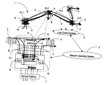
Figure 1 illustrates a portion of a photonic network 1, showing one fiber
chaining from a node 10-1 to a node 10-4. The nodes 10-1 to 10-4 are called
flexibility points, since they are provided with the ability to switch a
channel from
an input fiber to an output fiber of choice, and to add/drop traffic. It is to
be noted
CA 02393633 2002-07-17
that the invention also applies to networks with multiple port nodes, as shown
in
the insert for node 10-2, and that the traffic on any path may be
bidirectional. It is
also to be noted that a flexibility point may be a wavelength switch as in
Figure
1 A, or may be an optical add/drop multiplexes (not shown), which performs
optical add, drop and passthru (without switching channels from one fiber to
another).
An optical line system 8, shown between any two consecutive nodes
includes line amplifiers, pre-amplifiers, post-amplifiers and associated
dispersion
and power management equipment necessary for ultra-long reach propagation.
The routes of four optical signals A, B, C and D are shown as an example
of how the network operates. Signal A travels between nodes 10-1 and 10-4,
signal B travels between nodes 10-1 and 10-2, and signal D, between nodes 10-
1 and 10-3. A signal C is launched over the network at node 10-2 and exits at
node 10-3. In this example signals A, B and D are combined (multiplexed) at
node 10-1 into a multi-channel, or wavelength division multiplexed (WDM)
optical
signal and transmitted over the same optical fiber towards node 10-2. Other
channels may also be multiplexed on this line. At node 10-2, signals A, B and
D
are optically demultiplexed from the WDM signal. As node 10-2 is the
destination
for signal B, signal B must be 'dropped' to the local user, illustrated
generically
by service platform 7, while signals A and D pass through node 10-2 and
continue their travel towards node 10-3.
A flexibility site such as node 10-2 comprises an access demultiplexing
and switching stage 12 for routing each dropped channel, such as channel B, to
a respective receiver 18, and from there to the service platform 7. The access
stage 12 also provides for switching add channels, such as channel C, from the
service platform 7 to a selected output port of node 10-2. The switch stage 10
and access stage 12 have a broadcast and select structure that uses splitters/
combiners and tunable optical components such as blockers, filters. These
stages are also provided with low power optical amplifiers (amplets) to
compensate for the path losses across the respective stages. The access
structure is also provided with variable optical attenuators for each add
port, to
allow a slow turn-on of the optical components, as it will be seen later.
It is to be emphasized that the invention is not restricted to this specific
type of node, i.e. a flexibility site may perform switching and add, drop and
switching, switching only; the add/drop may also be asymmetric. In more
general terms, the invention applies to a dynamically reconfigurable WDM
9
CA 02393633 2002-07-17
network 1, where 'not all wavelengths are equal', i.e. the channels have a
different network traversing history, they may not have same path length or
same
origin and destination.
While channel A passes through node 10-2 in optical format, there are
cases when a passthrough channel, such as channel D in the example of Figure
1, needs to be OEO processed at node 10-2. Namely, in some cases signal D
needs to be moved on another wavelength (if e.g. the wavelength of the channel
carrying signal D is already used by another signal on the same fiber between
nodes 10-2 and 10-3). Wavelength conversion is performed in electrical format,
as it involves demodulation and modulation operations. As well, electrical
conversion is needed if signal D requires regeneration for conditioning (re-
timing,
re-shaping). To this end, the switching nodes of network 1 comprise a pool of
tunable regenerators 17 which can be attached to some of the spare drop/add
ports 15, and which are ready for carrying passthru channels if/whenever
needed. The optical regenerators 17, as well as the receiver terminal, have
the
capability to provide BER or Q information on the received traffic, either
through
a built-in test pattern detection mechanism, or via error counting
capabilities of
the Forward Error Correction (FEC) scheme, using a Q extrapolation approach.
It is evident that the distance traveled in the network 1 by channels A, B,
C and D is different. Therefore, only power equalization can be effected on
the
common path 10-1 to 10-2; OSNR equalization will unnecessarily degrade
channel B, or any channel shorter than A.
Network 1 is also provided with an intelligent network operating system
NOS 5 which is shown in some detail in Figure 1 B. NOS 5 enables photonic
constrained wavelength routing, network auto-discovery and self test, capacity
and equipment forecasting and network optimization capabilities. A line
control
system 6, shown in some detail in Figure 4, provides network 1 with embedded
photonic layer monitoring, which confers adaptive power and dispersion
control.
System 6 feeds real time line performance information to NOS 5.
As shown in Figure 1 B, the network operating system NOS 5 includes a
number of computation platforms, such as a network management platform 20, a
route management platform 21, and an embedded processing platform 22. In
general, the network management platform 20 performs network level functions,
route management platform 21 performs node-related functions and node
connection control, and the embedded platform 22 performs circuit pack and
CA 02393633 2002-07-17
component control. For example, the management platform 20 supervises the
operation of the network and the network elements, performs channel
provisioning in conjunction with a planning platform (not shown), provides
performance information collection for link operation monitoring, and also
provides system and security control.
Route management platform 21 is responsible with signaling and routing,
network connection control and optical link control. Platform 21 comprises a
network service controller NSC 26 at each flexibility site, which controls the
flexibility site on which it resides and potentially a number of optical line
amplifier and OADM nodes associated with optical links emanating from the
site. NSC 26 is equipped with a routing and switching R&S mechanism 28,
responsible with finding a plurality of A-Z paths for a given connection
request
and ordering the paths according to their estimated performance. The paths are
constructed based on class of service constrains, regenerator placement rules
and wavelength assignment rules. To order the paths, the R&S mechanism 28
uses an engineering tool 23, which provides the estimated Q for each link in
the
path, and assigns to the path the minimum Q for all links.
The engineering tool 23 uses data such as fiber loss, length and
dispersion measurements, wavelength power measurements, loop models and
loop states, and provides input signal ranges and output signal targets to the
optical power control loops. The engineering tool also delivers the Q margin
criteria or/and the Q thresholds.
Platform 21 constructs a network topology database, shown generically
at 25, by querying the embedded platform 22, which reports cards and shelves
identity, position and configuration. A resource utilization controller 24
provides the R&S mechanism 28 with the information about availability, type
and placement of regenerators and wavelengths, taking also into account
forecast on demands.
A network connection (or channel) controller NCC 30 is responsible for
the end-to-end light-path set-up across the optical network. NCC 30 collects
performance data from the line control system, as shown generically by
performance and monitoring P&M database 29, and connectivity data from
R&Ss 28. Database 29 may also maintain user-defined thresholds for these
parameters. Based on this real time performance information and on
thresholds preset for the monitored parameters, the management platform 20
11
CA 02393633 2002-07-17
decides if a channel needs regeneration or wavelength conversion, or decides
on an alternative route for traffic optimization.
A call manager 27 communicates the path request and the corresponding
constrains to the R&S mechanism and performs call accounting, administration
and availability. In network 1, a service (e.g. an A-Z path) can be set-up by
a
user by a simple point and click on a user terminal (not shown).
In network 1, the dynamics of network connectivity leads to dynamics in
physical transmission performance. A path may operate in four main operation
modes: set-up mode, monitoring mode, service mode, and tear-down mode.
Control and monitoring of these operation modes is in the responsibility of
the
management platform 20, based on a performance information collected in
database 29 and topology information collected in database 35.
The basic rules for the dynamic reconfiguration of the network provide that
any path set-up and tear-down operation should take place with minimum
disturbances to the existing channels on all sections of the path. On the
other
hand, once the new path is set up and in operation, all sections of the path
should be very tolerant of subsequent reconfiguration events.
Path set-up mode.
The term 'set-up' in the context of a connection over network 1, refers to
the procedures from a request to exchange traffic between a source and
destination terminal, until establishment of a path connecting these
terminals.
Path set-up takes place in a number of stages.
~ Pafh selecting stage
First, the R&S mechanism 28 receives a path set-up request either from
the network management platform 20, or from terminal 28. Call manager 27
processes the request by giving an ID to the connection, and transmits to the
R&S mechanism 28 and the NCC 30 connection ID and the constrains
associated with the request (e.g. pass through node 10-3). The call manager
obtains a list of best paths calculated by the R&S mechanism 28, using
engineering tool 23. The paths in the lists are ordered according to preset
criteria, such as for example the cost, or set-up success probability,
determined
using engineering tool 23.
~ Path reservation stage
Next, once the best paths are identified for a given request, the Call
manager 27 passes the paths (starting with the best one) to the internal
signaling
12
CA 02393633 2002-07-17
layer of R&S mechanism 28 on the associated NSC 26, for reserving the
resources along the path. The internal signaling layer also passes the
connection
data to all NSCs of the nodes involved in the connection (passthru and
destination) for reservation of the resources of the entire path. Once the
resources along the entire path are reserved, the signaling layer passes this
information to the NCC 30 of NOS 5.
~ Path turn-on stage
The NOS 5 instructs all nodes in the light-path, which are in the example
of path A nodes 10-1, 10-2, 10-3, and 10-4 to connect as needed. That is, it
instructs node 10-2 and 10-3 to proceed with passthru and instructs node 10-4
to
proceed with access drop. (In the case of the other connections on Figure 1A,
NOS 5 instructs the node 10-2 to proceed with access drop for connections B
and D, or to proceed with access add for connection C).
The transmitters and receivers allocated to the respective A-Z path are
now powered-up, the transmitters are tuned on the wavelength allocated to the
respective link, and begin transmitting the respective channel wavelengths.
To account for, and monitor both fast unplanned transience (such as
EDFA transience and some polarization induced impairments, which rapidly
settles down after an initial performance degradation) and performance
variations
due to slow drift/ageing and planned network churn events, a number of Q/BER
integration time constants are preferably incorporated in the line control
system.
It is known that the performance of a channel increases with the signal
power, because the OSNR increases with the optical signal power. However, as
the optical power is further increased, the impact of non-linear effects (four
wave
mixing, cross phase modulation, self phase modulation, etc.) on the signal
quality
increases, and at some point the performance starts to degrade at higher
optical
powers.
An adaptive channel power turn-on procedure is used for setting-up a new
path in network 1. Rather than simply turning on the optical power to the
maximum power as in the traditional systems, according to the invention
optical
power is slowly introduced along the paths to ensure that optical amplifiers
and
amplets, which are shared with other channels, behave predictably, and also to
allow tuning of optical components along the connection.
At the beginning, while there is optical power at the output of the
transmitters, this power is attenuated so that there is no light arriving at
any
receiver. The slow turn-on procedure not only prevents fast transience in the
13
CA 02393633 2002-07-17
network, but also allows data collection for all established connections
sharing
common sections with the new path.
The BER of the signal is monitored as the optical power is increased, until
an acceptable BER for the entire path is achieved at the receiver. This
procedure
is described in further details under the title "Adaptive channel power turn-
on
procedure"
~ Path testing sfage
Once the light-path is fully connected from end-to-end, across the
network, the NCC requests a quality measurement from all termination points in
the path (receivers of the regenerators, wavelength converters and the
destination receiver). Now, the line control system 6 extracts performance
data
from all links and compares this data with a start of life "margin tolerance",
or
"test threshold". If there is sufficient margin hedge against potential
network
performance degradation in the life of the path connectivity, or if the path Q
is
above the test threshold, the path set-up is considered successful and the
path is
marked as 'existing'.
If the light-path does not meet its margin or threshold target, the NOS 5
turns-off the path and tries a wavelength upgrade for the respective
connection.
A wavelength upgrade is particularly applicable to paths including none or one
regenerator, and implies finding a new wavelengths) that has higher chances to
succeed for the respective link loading, length and fiber type.
If the light path still does not meet its margin or threshold target, NOS 5
tries the next level of regeneration in the list of best paths. Thus, a
regenerator is
switched in the path at one of the intermediate nodes (in the example of
Figure
1A at one of intermediate nodes 10-2 or 10-3). To this end, the NOS inquiries
the resource utilization controller 24 to discover a free regenerator 17 that
can be
allocated to the path. Once a free regenerator is switched in the path, the
test is
repeated, until a path from the list can be marked 'established'. If all the
paths in
the list fail, the NOS 5 fails the light-path setup.
Path monitoring mode
The term 'monitoring' refers to the normal operation of a path for
transporting traffic between the transmitter and receiver terminals. During
this
stage, the network starts monitoring the path performance, particularly during
the
establishment and abolishment of other paths, which share common sections
with this existing path. The path is maintained as long as its performance is
better than a "churn threshold" or a "maintenance threshold".
14
CA 02393633 2002-07-17
For collecting monitoring data, signals are sampled and processed in the
digital domain. A signal must be sampled at a rate greater than or equal to
twice
its maximum frequency component. A number of different techniques can be
used for cases where the sampling rate is not fast enough. These techniques
can
only be used for a class of signals that may have a high frequency component
with a low periodicity. Averaging of samples of signals in this class prevents
exaggerated loop responses. Another useful filter takes multiple samples and
discards the data if there is a significant change over the sample interval. A
third
method uses the knowledge of the event origination to suppress and sequence
the system response.
Ideally, the network operating system ensures that a path always stays
just slightly above or on the threshold during the life time of the path - the
best
compromise between network cost and performance expectations is maintained
in this case.
Path maintenance (service mode
The path may enter into a service mode under certain circumstances.
Relevant to this specification, is the case when the path performance reaches
or
falls below the "churn threshold" or the "maintenance threshold" during the
life of
the connection. In this case, the path enters into a "churn management" stage
or
a "maintenance" mode. In this stage, either a new end-end route is calculated
by
the R7S mechanism 28, and established, or a regenerator is deployed as during
path set-up stage described earlier.
Path tear-down mode
The term 'tear-down' refers to removing a connection. This implies
attenuating the power at the transmitters and blockers, inhibiting the traffic
restoration procedures, removing the deleted wavelengths) from the steady
state control, and turning-off the transmitters and the receivers along the A-
Z
connection.
The same approach to processing a connection is used during the
deployment of a new network, as well as in network reconfiguration, which
involves old traffic tear-down and new traffic set-up in a partially filled
network.
A flow chart describing an embodiment of a linear Testing, Margin
hedging, Monitoring and Churn Management (TMMCM) procedure according to
an embodiment of the invention is shown in Figure 2A. At step 100, a request
for
a new connection is received and the network operating system set-up mode
CA 02393633 2002-07-17
starts, as shown at step 101. First, the network calculates a number of end-to-
end paths for servicing the request and selects the best path, as shown in
step
102. In the example of Figure 1A, management platform 20 determines that a
physical route between nodes 10-1 and 10-4, which satisfies the connectivity
request is a route passing through nodes 10-2 and 10-3. A wavelengths is
allocated to this connection; however, if the path has one or more
regenerators,
there could be more wavelengths allocated to this path.
Next, the margin tolerance and the churn threshold are calculated in step
103, as it will be seen later under title "Margins and thresholds".
After the path is turned-on, step 104, the Q factor for the new path is
measured at the receiver, as shown in step 105.
The measured Q factor is compared with the margin tolerance, step 106.
If the connection performs above the margin tolerance, the path is acceptable
for
use and marked as such, i.e. is declared an "established" path (or "active",
or
"existing"), step 108. If the measured Q value is under the margin tolerance,
the
network operating system 5 looks for a wavelength upgrade or a regenerator 17
available at one of the intermediate nodes, and the channel is OEO converted
at
that intermediate site for processing. End-to-end connectivity is
reestablished
through a regenerator, as shown in step 110.
The 'existing' path is now monitored, by continuously measuring the Q
factor, step 112. The performance of the path changes as new paths are set-up
or removed from common links, such as links 10-1 to 10-2, 10-2 to 10-3 and 10-
3
to 10-4 in the example of Figure 1A. It is possible for path A to perform
under the
churn threshold in certain circumstances, branch NO of decision block 114. In
such a case, the path enters in the path service mode, step 116, in which case
the network operating system 5 looks for a regenerator 17 at an appropriate
intermediate flexibility site, or switches the connection over a new paths
that may
have better chances of performing under the current network churn conditions,
step 117.
In the case when a request to tear-down the path is received while the
path operates above the maintenance threshold, step 118, the tear-down
procedure is performed in step 120.
A main issue to address with all optically switched DWDM networks 1 is
the inter-channel interference when new channels are set and/or torn down.
This
16
CA 02393633 2002-07-17
can also be managed as a part of the TMMCM procedure, which is best
described as a state machine as shown in Figure 2B.
Figure 2B shows how the path state changes between the service mode
state 300 and monitoring mode 310. If path performance is above the margin
tolerance the path transits from service mode 300 to monitoring mode 310. If
path performance is below a churn threshold, it transits from state 310 to
state
300.
The TMMCM procedure can in addition be an effective tool to manage
tolerances in path installation, component/sub-system manufacturing and ageing
(when there are significant network reconfiguration activities over time)
because
the margins are adjusted every time a path is set up based on the real time
performance of all network elements that constitute the physical path.
A flow chart describing another embodiment of a path engineering
procedure is shown in Figure 3. Steps 200, 201 and 202 are similar to the
first
three steps of the flow diagram of Figure 2A. In step 203 two path thresholds
Qtest and Qservice are selected based on actual (life) path measurement to
allow
added flexibility to the process, as it will be seen later under title
"Margins and
thresholds".
After the path was turned-on, step 204, the Q factor for the new path is
measured at the receiver, as shown in step 205. The measured Q factor is
compared with the test threshold, step 206. If the measured Q factor is above
Qtest, the route is marked as "established", step 208. If the measured Q value
is
under the Qtest, the network operating system 5 provides another path and the
connection is switched form the old path to the new one. In this case, the
operations disclosed for the path set-up mode are repeated, steps 201-206. The
new path may use the same physical route, but upgraded wavelengths, or
additional regenerators placed in the path, or may use another physical route
between the source and destination nodes. End-to-end connectivity is
reestablished through the new path, as shown in step 210.
Each path is tested and maintained using control loops that account for
the actual hardware along the route. A measurement of Q (or the equivalent
BER) is used to determine if the performance is adequate to allow the path to
be
set and maintained, shown in step 212.
17
CA 02393633 2002-07-17
If the path performance degrades under Qse~,;ce, branch NO of step 214,
the path enters in service mode, step 210, in which case the network operating
system 5 looks for a path upgrade (upgrading the wavelengths, or/and adding
regenerators 17) or for a new path that may have chances to perform better.
In the case when a request to tear-down the path is received while the
path operates in monitoring mode, step 218, the tear-down procedure is
performed in step 220.
Adaptive channel power turn-on procedure
There are significant benefits to using the adaptive power turn-on
procedure described above. This procedure allows connections established
along shorter optical paths, or those with transmitter and receiver pairs from
the
high end of the performance distribution, to have lower launch powers than
connections established along longer paths. As a result, the total optical
power
needed from the optical amplifiers is reduced, thus reducing their cost. A
lower
launched power also reduces the cross-talk added by wavelengths with short
optical paths, thereby increasing the performance of the co-propagating
channels.
As indicated above, typically the channel power is set at a maximum, and
this maximum is determined from simulation and measurement and is a
provisioned system parameter. However, the traditional setting assumes that
the
transmitter power is launched directly into the outside plant fiber.
Nonetheless, in
actual deployment of a new connection, the power launched into the outside
plant fiber is reduced by the amount of in-building fiber and connector loss,
which
is not accounted for. On the other hand, the adaptive channel power turn-on
procedure described above determines the actual maximum useful channel
power for the real system conditions, thereby overcoming the effect of the
variable in-building loss on system performance.
Still another advantage of the adaptive channel power turn-on procedure
is that, if the BER of a connection degrades for any reason (aging,
temperature,
polarization effects, cross-talk due to channel loading, etc), the optical
power can
be increased until an acceptable BER is achieved, or the maximum channel
power is reached.
Still yet another advantage of this method is that it provides a means for
the system to compensate for performance degradations by first increasing the
channel power, and only thereafter, if the path performance is still
unsatisfactory,
18
CA 02393633 2002-07-17
the network proceeds with upgrading the wavelength set used for the respective
path, or switching a regenerator in the path, or switching the connection
along
another path.
Margins and thresholds
Traditional WDM systems require a fixed span performance margin,
compatible with any combination of transmitter, receiver, optical amplifiers,
filters
and fiber. In reality, some paths operate with a much higher margin than
others,
resulting in an inefficient use of network resources. In addition, this fixed
performance margin is selected to achieve the desired performance of the span
over the entire lifetime of the product and over any span loading conditions.
In
this way, regardless of age or loading, the performance of the traditional
network
is limited to the worst case scenario, resulting in higher first cost and
higher
lifecycle cost.
On the other hand, the network according to the invention uses in one
embodiment, as shown in Figure 2A, two "margins", one for the testing stage
during set-up mode, and one for the monitoring mode. Thus, the margin
tolerance can be set so as to allow sufficient margin hedge against potential
network performance degradation during the life of the path, and the churn
threshold can be set based on network churn information.
Also, because of the hysteresis of the network physical connectivity, the
performance of a path depends on the loading conditions in all sections of the
path, which are also accounted for in the margins.
The "margin tolerance" and "churn threshold" and are allocated flexibly,
conferring a means to minimize the cost of the system under any conditions.
These margins can be individually calculated for each channel, taking also
into
account components ageing and temperature variations, as well as a variable
margin to account for channel loading. Furthermore, the margins can be a
negotiated value based on customers' tolerance to price and network churn.
The path margin tolerances are determined by averaging or integration of
the measured parameters) over a period of time (time constant). This time
constant is relatively long because a proportion of the margin tolerance is
allocated in the system to cover some of the fast temporal variations of the
transmission system. In this way, these fast transience or drifts do not
trigger the
network maintenance (service) mode, since they were already accounted for.
This time constant can be also a customer negotiated value as this will also
have
19
CA 02393633 2002-07-17
an impact on the amount of churn the transmission paths will see over their
operation life time.
While this approach gives high flexibility to controlling operation of a path,
it can be rather complex when the number of the existing connections and of
the
new requests is high. In such cases, instead of using the margin approach, the
above two Q thresholds can be used for wavelength path set-up and
maintenance.
As indicated above in connection with Figure 3, Qtest is the Q value that
must be achieved on path set-up to declare a path established, while Qservice
is
the Q value that triggers a maintenance activity. Qservice is selected so as
to
maintain a virtually error free output even when the path is in the service
mode.
When during the service mode the path Q degrades to Qservice, the network
operating system 5 triggers an alert to the user and finds a new path between
the
terminal locations of the degraded path. This new path may follow a different
route, have additional intermediate regeneration added, or have lower
impairments than the degraded path; in other words has a Q greater than Qtest
Both of these Q thresholds are provisionable and hence allow the end
user to trade off performance margin (and hence initial cost) against network
churn (switching existing wavelength paths to new wavelength paths). This
method also allows the end user to base the performance margin on real-time
data from the network, rather than on theoretical calculations, resulting in
greater
accuracy and less wasted performance. This provides in the end for further
reducing the lifecycle network cost and greater flexibility in the operation
of the
network.
Optical power control loops
Control on per channel power, rather than relative OSNR is required in an
dynamically reconfigurable network, as each channel will have an arbitrary
OSNR dependant on its distance from source.
Network reconfiguration is enabled by optical control loops that sample the
signal at given intervals and compare the averaged samples with performance
targets. The link/network control has a layered architecture. The loops are
controlled using the entities shown in Figure 4.
The control loops are provided for setting and maintaining the parameters
of the network optical devices within the operational ranges, so that the
network
is unconditionally stable. It is a design requirement that steady state
operation of
CA 02393633 2002-07-17
the control loops optimize the network for maximum reach. Maximum reach
could be for example summarized as the minimum total number of network
regenerators.
Optical widget controllers OWC 37 provide the interfaces to the various
optical modules that make-up the network 1. They set the control targets for
the
optical modules, read run-time data and intercept asynchronous events. The
OWC has a generalized interface to the optical module, and the vendor specific
details are contained within the device drivers. OWCs are provided for example
for the EDFAs (Erbium doped fiber amplifiers), Raman amplifiers, DGEs
(dynamic gain equalizers), OSAs (optical spectrum analyzers), tunable filters
(TF), VOA (variable optical attenuators), transmitters (Tx), receivers (Rx)
and
wavelength blockers (B), and are provided for both direction of transmission.
The optical group controllers OGC 35 coordinate the actions of various
optical modules in an amplifier group, and implement a span control loop, to
achieve a control objective for the group as a whole. An amplifier group is
defined as the EDFAs, the Raman amplifiers, the DGEs monitored by an optical
spectrum analyzer OSAs, in the same line system. More precisely, the network 1
is provided with a plurality of OSAs which enable visibility of signal power
levels
and noise levels. Each OSA module is shared by a number of optical
components to provide control loops for e.g. transmitter power, blocker
control,
amplifier control. Fault monitoring also rely on this information to localize
failures
in the network.
The optical link controller OLC 34 is responsible with all control activities
that fall within the scope of a single line system. As indicated above, the
link
(line) is the fiber and associated amplifier groups) between two flexibility
points.
The OLC 34 is responsible with commissioning the line system, re-provisioning
the line system's OGC's as required following power cycles and certain restart
scenarios, line system topology discovery and channel provisioning.
An optical vertex controller OVC 33 is responsible for connection and
power control through the wavelength switch. Connection and control of
interface transponders, regenerators and wavelength translators also falls
within
the scope of the OVC.
NCC 30 provides the type of the actual connection (connect through,
connect a regenerator, connect access and connect a receiver) and
accomplishes the end-to-end light-path set-up by coordinating activities of
various OVCs 33 and OLCs 34 along the light path route.
21
CA 02393633 2002-07-17
Each individual link can be put in steady state control or open loop mode.
A wavelength is changed from open loop (set-up mode, maintenance mode) to
steady state control (monitoring mode) after it has been added to the network.
Figure 5A shows the flow of information between the optical devices 45,
the line control system 6 and the network operating system 5. There are three
levels of control shown generically on Figure 5A, namely the loop level
control,
the OLC/OVC level control and the NOS level control. The loops are designed to
allow a level of abstraction at these boundaries, such that changes can be
made
independently. For example, optical devices 45 store their own specifications,
so
that it is possible to change the device specifications without changing the
loop
control 40
At the first level, a loop control 40 receives information, such as device
specifications 41, device states 42, device measurements 43 from various
optical
devices 45 connected in the respective loop. The loop control 40 uses this
information to control the device, by sending control information 44. An
example
of device specification is gain and attenuation range for a wavelength cross
connect.
At the next level, an OLC (optical link controller) 34 manages one or more
span loop controls 40. It receives loop turn-up measurements 51, loop
specification information 52, loop state information 53, loop measurements 54
and loop alarms 55. The span loop requires for example fiber type and
wavelength power targets, so that the OLC 34 sends control information 56 and
57 to the respective loop control 40. The OVC (optical vertex controller) 33
controls the switch and drop loops, that require wavelength power targets 57.
Other information, not shown on Figure 5A, may also be used to control the
loops, such as dispersion targets for link commissioning.
Examples of turn-up measurements are Raman gain, path loss, and
module specifications including maximum DCM (dispersion compensation
module) power. In response, the OLC 34 sends control signals such as link gain
distribution, launch power range.
Examples of loop state information are number of active channels, gain
degradation, pump power usage. In response, the OLC 34 sends control signals
such as requests to modify link gain distribution and available launch power.
At the NOS control level, the OLC/OVCs transmit alarm information shown
at 46, supply performance and monitoring data to P&M database 29, and supply
topology data to topology database 25.
22
CA 02393633 2002-07-17
OLC 34 and OVC 33 are controlled by the NCC 30, as also shown in
Figure 4, and by engineering tool 23.
As indicated above in connection with Figure 1 B, engineering tool 23
estimates optical path Q necessary for path selection and ordering.
The interaction of control loops must create the intended network
response to changes, and maintain stability during steady state operation. For
example, when routing a path through multiple WXCs 10 and links, the launch
power, the gains of the switches and the link gain need to be compatible. This
is
achieved with a network wide standard, using for example unity gain or a per
optical channel serial construction.
Figure 5B shows a control loop and stimulus propagation. In the first
case, the arrival of a stimulus signal at each loop initiates a loop response,
according to the loop transfer function H(s). Signals can also propagate
transparently through control loops. Transparent propagation creates a
situation
where many loops can see a stimulus but only one must responds.
Signals generated by loop responses branch and converge. Loop
interaction is designed to allocate the network response to the appropriate
set of
loops and in the correct order. Such a scenario is shown in Figure 5C, which
illustrates how a control signal stimulates a network of control loops. A
coupling
coefficient can be used to describe loop interaction. Unwanted loop
interaction
must have a low coupling coefficient. The bandwidth and order of interacting
loops must be selected as a tradeoff between minimum excursion error and
maximum response. The response of a loop must also be chosen to be
compatible with the sampling rate of a downstream (or outer) loop.
Figure 6A shows a gain loop and Figure 6B shows a vector loop. In the
example of the gain loop, input output sampling with a gain target confines
the
loop to respond to changes within its own domain, and reduces or eliminates
the
interaction with adjacent loops. The gain control signal is calculated such
that
the loop behaves as a linear time invariant (LTI) system. A difference in
input
and output sampling times can couple an unwanted 'common mode' component
into the Poop response. The coupling coefficient is small if the time
difference is
small relative to the period of the maximum frequency component of the signal.
A vector loop has a gain or power target for a plurality 'n' of channels, but
does not operate as a set of 'n' independent loops. The error signal generated
is
a vector with 'n' elements. The loop seeks to minimize the energy of the error
vector.
23