Note: Descriptions are shown in the official language in which they were submitted.
CA 02393929 2002-06-10
WO 01/45281 PCT/GB00/04836
1
RADIO SYSTEM WITH CORDLESS REMOTE PTT MODULE
The present invention relates to a radio system and particularly, but not
exclusively, to a
system employing what are commonly known as personal role radios as typically
carried
by members of the armed forces or organisations such as the Police. Here there
is often a
requirement for an individual to have a personal role radio to permit two way
communication.
Conventional two way radios operate in either duplex or simplex mode, the
duplex mode is
similar to a telephone system where the receive and transmit paths are both
open and both
parties can speak to each other with no other requirement.
to
The more common operation is simplex where the transmit path of each radio
only works
when the transmitter is keyed by the operation of a "press to talk switch"
(PTT). The types
of switch used vary and can be either part of a microphone as in the case of
the hand held
types in common use, or a switch box in a lead between the radio and a
headset, as used in
commercial and operational headsets.
Operators often have to operate a radio transmit switch while using their
hands to do other
things and certain systems incorporate voice activation where the radio is
switched at the
detection of the users voice from the microphone. This technique is not
reliable with some
applications and the need for a switch actuated by the user is till the only
reliable means of
controlling the radio.
CA 02393929 2002-06-10
WO 01/45281 PCT/GB00/04836
2
According to the present invention there is provided a radio system comprising
a radio
having a transmit mode, the system further comprising a cordless remote module
in which
a press to talk (PTT) switch is housed and used to set the radio to the
transmit mode, the
remote module comprising a short range, relative to the radio, transmitter,
the system
further comprising a receiver associated with the radio for receiving signals
from the
remote module to set the radio to a transmit mode.
Employing the present invention enables an operative to locate a remote module
at a
convenient location, for example the stock of a rifle, steering wheel of a
car, handlebars of
a motorbike or at the controls of a fast boat, while locating the radio
elsewhere. Thus the
operative may push the PTT switch and reply to any received communication
without
needing to move away from the controls or duly distract himself from his
current activity.
The short range transmitter is advantageously a radio transmitter but could be
an infra-red
transmitter, which may be acceptable in certain applications.
Where an operative needs to communicate via two radio networks, as may occur
in a
military application where the operative needs to communicate locally via a
personal role
radio but may also wish to have access to a combat network radio, it is
desirable that the
remote module comprises two PTT switches respectively associated with
different radio
networks. It is particularly advantageous that a signal transmitted from the
remote module
comprises a code and that the receiver is responsive to the code, thereby
avoiding
unintended operation of transmitters in the vicinity of the remote module
which may not be
associated with the remote module.
CA 02393929 2002-06-10
WO 01/45281 PCT/GB00/04836
3
It may be desirable that the receiver is responsive to a variety of codes
associated with
different remote modules. In this manner an operative may have a plurality of
remote
modules associated with different items of equipment, for example a motorbike,
a rifle or a
motor car. Each may have a remote unit semi-permanently installed on those
pieces of
equipment.
A very significant problem associated with having a code associated with a
remote module
and a receiver that only accepts a signal with that code arises if that remote
module, which
to may be small and easily misplaced, is lost or damaged. However this problem
can be
overcome by employing a receiver which has a "learn" mode in which it can
learn the code
of a remote module. This is possible because, unlike other remotely operated
key fobs on
motorcars or the like, there is no security aspect involved. Therefore it is
permissable for
the radio, or the receiver associated with the radio, to learn the code of the
remote module.
This is also particularly advantageous in applications where remote modules
are
permanently fitted to items of equipment such as a motor vehicle or motorbike.
Taking a
Police motorbike again as an example, if this is fitted with a remote module
any Police
rider can ride that motorbike and use their own personal radio, requiring only
that when
mounting the bike for the first time they programme their receiver with the
code of the
remote module on that bike.
The system advantageously employs a receiver which has associated with it a
magnetically
operated switch and a remote module comprising a magnet, the magnet and
magnetically
operated switch being arranged such that the magnetically operated switch is
caused to
CA 02393929 2002-06-10
WO 01/45281 PCT/GB00/04836
4
adopt a learn mode position when the remote module including said magnet is
held in an
appropriate position relative to the magnetically sensitive switch, in which
position
activation of the PTT switch on the remote module causes the receiver to learn
the code in
the remote module. Although this function could equally be achieved by pushing
a
screwdriver possibly in a small reset hole the magnet arrangement is
particularly
advantageous as it needs no other tools, only the remote module, to set the
code.
Advantageously depressing the PTT switch on the remote module a number of
times, or
for a period in excess of a pre-determined period, causes any codes within the
receiver to
to be removed from the receiver so that the receiver is no longer responsive
to those codes.
In this manner a receiver can be responsive to multiple codes, for example
permitting a
number of Police riders to ride common motorbikes. However when two riders who
commonly share two bikes are out on patrol together they can reset the
receivers associated
with their respective radios to ensure that operation of the remote module on
one particular
motorbike only operates the correct radio associated with the person riding
the bike and not
the radio of his colleague.
The receiver for the signal from the remote module may be located in the radio
itself but
alternatively the receiver may be located separate from the radio but wired to
the radio.
Preferably the radio has an additional PTT switch in electrical contact with
the radio, the
additional switch being arranged to function parallel with the PTT switch of
the remote
module. This may provide a convenient backup should the remote module fail or
be
misplaced. It may also have particular advantages in certain applications.
Refernng again
CA 02393929 2002-06-10
WO 01/45281 PCT/GB00/04836
to the Police motorbike application, this will enable the rider to leave the
motorbike with
his personal role radio with a PTT switch on his person associated with that
personal role
radio so that the radio can be operated while he his away from the remote
module located
on the bike.
5
The additional PTT switch may be located in a unit separable from the radio
with the
receiver signals from the remote module also being in that separable unit. In
this manner
the radio may be remote from the separable unit. This may be advantageous
where an
operative may wish to leave a personal role radio, for example in a fixed
location on a
to vehicle, but have it wired to an interface connected to the separable unit
with the PTT
switch. The separable unit may then be mounted adjacent to the operatives
normal seating
position within a vehicle. In this manner the operative may use the PTT switch
on the
separable unit which may also have a connection for his headphones. In
addition a further,
smaller remote module may be mounted directly on the controls used to operate
the vehicle
so that an operative doesn't need to remove his hands from those controls.
One embodiment of the present invention will now be described by way of
example only
with reference to the accompanying figures of which:
2o Figure 1A is a perspective view of a personal role radio in accordance with
the present
invention;
Figure IB is a perspective view of a universal communication interface (UCI)
in
accordance with the present invention;
CA 02393929 2002-06-10
WO 01/45281 PCT/GB00/04836
6
Figure 2 is a perspective view of a remote radio interface;
Figure 3 shows the assembled apparatus of Figure 1B and 2;
Figure 4 shows the assembled apparatus of Figures 1A and Figure 1B with
auxiliary
components;
Figure 5 illustrates an alternative universal communication interface with
self-contained
1o speakerand microphone;
Figure 6 illustrates the various communications equipment that interfaces with
the
universal communication interface of Figure 1B;
Figure 7A schematically illustrates the primary components within the remote
module
illustrating Figure 6; and
Figure 7B illustrates the primary components of the UCI of Figure 1B and
Figure 6 which
relate to remote operation of the UCI by means of the remote module of Figure
7A.
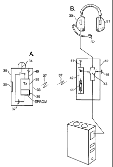
Refernng now to Figure 1, a personal role radio is illustrated generally as l,
having a
casing 2, a battery compartment cover 3, operating controls 4 and 5, and an
end face
constituting a radio interface 6. The interface 6, has a fitting slot 7,
fitting thread 8 and
electrical interconnects 9, 10 and 11.
CA 02393929 2002-06-10
WO 01/45281 PCT/GB00/04836
7
The personal role radio 1 comprises an aerial, (which is internal on the
embodiment
illustrated), a transmitter and receiver by which it may send and receive
radio signals. The
personal role radio is designed to be carried by an operative and would
typically be carried
on a belt or could be mounted in close proximity to the operative, for example
on a vehicle
associated with the operative.
The radio interface 6 is designed to receive the universal communication
interface (UCI)
indicated generally as 12 in Figure 1B. The UCI 12 comprises a stud not shown
and screw
1o I3 which co-operate respectively with fitting slot 7 and fitting thread 8
to hold the UCI
housing 14 in position. The UCI 12 comprises a headset connector 15, push to
talk (PTT)
buttons 16 and 17 respectively associated with two different radio networks
and two slots ,
only one 18 of which is shown, for receiving optional cable connections.
The switches 16 and 17 are depressed in order to talk to respective
communication
networks through respective radios, one button 16 is associated with the
personal role radio
1 of Figure 1A, while button 17 is associated with a external radio network,
which may be
a combat network radio where the radio system is employed in a military
application.
2o The universal communication interface comprises circuitry to ensure that
when a signal is
being received on one communication network the press to talk function
controlled by the
button associated with the other network cannot be activated. This ensures
that a radio
signal being received and transmitted to a user, possibly by means of a
headset, cannot
CA 02393929 2002-06-10
WO 01/45281 PCT/GB00/04836
8
inadvertently be picked up by the open microphone and simultaneously
transmitted on the
other radio network.
When the radio of Figure 1A is mounted to the UCI of Figure 1B and an
appropriate
headset or speaker/microphone are connected to the UCI there is a self-
contained personal
role radio which may be carried by an operative, the radio interfacing with
the universal
communication interface via contacts 9 and corresponding contacts (not shown)
on the
universal communication interface 12.
There are applications where it is not convenient for the operative to carry
the personal role
radio, or where the operative may wish to use another radio, perhaps mounted
in a vehicle.
Indeed the operative may wish to mount his personal role radio within a
vehicle. This is
facilitated by the remote radio interface 19 of Figure 2 which is identical to
the interface 6
on the personal role radio on Figure 1A, but instead of being part of that
personal role radio
is now a stand alone interface which may be connected to another radio which
could be
mounted on board a vehicle, aircraft, boat etc, or a large Man-pack infantry
radio, by
means of connection lead 20.
The remote radio interface 19 comprises the same physical and electrical
connections as
the interface 6 and thus the UCI can be mounted to the remote radio interface
19 as shown
in Figure 3. Referring now to both Figures 1B and Figure 3, slot 18 in the
LTCI 12 may
receive a cable with contacts on a spade which connect to contacts 10. A
corresponding
slot (not shown) on the other side of the UCI permits a similar cable with
contacts to
connect with the contacts 11 on the interface 6 or 19. These additional leads
are illustrated
CA 02393929 2002-06-10
WO 01/45281 PCT/GB00/04836
9
in Figure 4, lead 21 being connected and lead 22 shown disconnected in order
to illustrate
contact spade 23 which connects to contacts 11 of figures 1A and 2.
In the arrangement shown in Figure 4, the UCI 12 is mounted on the personal
role radio 1
but could equally be connect to the remote radio interface 19 of Figure 2, as
shown in
Figure 3. Lead 21 may be connected to an auxiliary radio depending on the
application,
whilst leads 22 connects remote switches 24 and 25, corresponding to press to
talk
switches 16 and 17 to the UCI 12. The additional switches 2~ and 25 may be
located at a
position convenient to an operative for example, on the handlebars of a
motorcycle or quad
to bike or on the stock of a rifle. This permits the radio to be operated
without the operative
needing to remove his hands from the controls of the vehicle or from a gun he
his carrying.
Alternatively, depending on the application, this function may be satisfied
simply by
having the UCI 12 mounted on the remote radio interface 19 as shown in Figure
3 and
having the complete unit then mounted at an appropriate location, either on a
vehicle or
perhaps on a chest holster worn by an operative. It will be realised that
there are any
number of permutations which a remote universal communication interface 12
permits.
Refernng now to Figure 5, there is illustrated a variation of the universal
communication
interface of Figure 1B. Here UCI 26 incorporates a microphone 27 and speaker
28 such
2o that it can be operated without a headset. In the embodiment illustrated
there is only a
single push to talk switch 29 but this is a matter of design choice. The UCI
26 interfaces
with the personal role radio 1 of Figure 1A, or the remote radio interface as
illustrated in
Figure 2, in exactly the same manner as the UCI 12 illustrated in Figure 1>3.
CA 02393929 2002-06-10
WO 01/45281 PCT/GB00/04836
Both UCI's 12 and 26, illustrated respectively in Figures 1B and Figure 5,
incorporate a
radio receiver, (which could equally be an infra-red receiver). The function
of this receiver
is described below with reference to Figure 6 where, for illustrative purposes
only, the UCI
12 of Figure 1B is shown connected to a headset, illustrated generally as at
30 having
5 headphones 31 and a microphone 32 located on a stalk which when worn by an
operative is
in front of the operatives mouth.
In the embodiment illustrated in Figure 6 the UCI 12 is mounted on the remote
radio
interface 19 previously described with reference to Figure 2. The radio system
additionally
10 comprises a cordless remote press to talk (PTT) module 33 having a PTT
switch 34
thereon and a magnet 35, located adjacent the wall of the casing 36 of the
remote module
33. The remote module 33 comprises a low power transmitter arranged such that
operation
of the PTT switch 34 causes a signal 37 to be transmitted to the UCI 12 which
when
received by the receiver (not shown) of the UCI 12 the UCI functions as though
the PTT
switch (16) had been depressed.
The function of the remote module is described below in more detail with
reference to
Figures 7A and 7B, however it should be noted that although only one PTT
switch 34 is
illustrated on the remote module 33, in order to simplify the description, the
module 33
could comprise twa switches corresponding to the switches 16 and 17 of the UCI
if the
module is desired to be used with a UCI designed to operate with two networks.
Referring to Figure 7A the remote module 33 is shown schematically to comprise
a battery
37 connected by PTT switch 34 to transmit circuit 38. When the switch 34 is
depressed the
CA 02393929 2002-06-10
WO 01/45281 PCT/GB00/04836
11
battery is connected to the transmit circuit which retrieves a code from EPROM
39. This
code is effectively unique to the remote module and is transmitted in a signal
via antenna
40 to receiving antenna 41 housed within the UCI 12 illustrated schematically
in Figure
7B, with the function of only one PTT switch 16 illustrated for clarity.
Refernng to Figure 7B the PTT switch 16 connects the microphone 32 to the
personal role
radio 1. (The communication path to the headphones 31 has been omitted for
clarity).
Although the headset is shown connected via UCI 12 to personal role radio 1
the radio
could be any radio. The microphone 32 may be connected to the personal role
radio 1 by
1o means of switch 16 or by means of signal received by receiver 42 via
antenna 41. The
receiver 42 when receiving the correctly coded signal closes switch 43. It
should be noted
here that although Figure 7, and description thereof, talks about opening and
closing
switches and the switches are illustrated as being physical switches contained
within the
UCI 12, in practice this function may be achieved electronically and indeed
may be
achieved by generating an appropriate signal to the transmitter contained
within the radio
1.
In order that the receiver 42 may learn the code which the remote module 33
will transmit,
the remote module 33 may be held adjacent the UCI 12 with magnet 35 adjacent a
2o magnetically sensitive reed switch 44 in the receiver. With the magnet 35
adjacent the
reed switch 44, the reed switch closes setting the receivers circuit to a
'learn' mode. An
operative depressing the PTT switch 34 of the remote module 33 causes the code
stored
therein to be transmitted from the remote module 33 to the receiver 42, which
code is then
CA 02393929 2002-06-10
WO 01/45281 PCT/GB00/04836
12
stored in memory in the receive circuit 42 and subsequently recognised as an
appropriate
code.
The receiver 42 may learn a number of codes such that it is responsive to
signals from a
corresponding number of remote units. To reset the receiver and wipe out all
stored codes
the magnet is held adjacent the reed switch and the PTT switch 34 of the
remote module 33
pressed five times in quick succession. The receiver circuit 42 is programmed
to recognise
this as a 'clear all codes' signal. Alternatively the receiver could be
programmed to
recognise a signal lasting longer than a set duration.
It will be realised that apparatus in accordance with the invention may have
any number of
applications and the particular applications are outside the scope of the
present
specification. However for illustrative purposes a brief reference to one
application of the
invention is given below with reference to a rider of a Police motorcycle.
The Police rider would typically have a personal role radio mounted upon his
person
complete with a headset and UCI, the UCI either being mounted directly to the
radio or
perhaps strapped to his chest. The advantage of this is that whether on the
bike or
dismounted the Police rider carries his complete radio system with him.
However whilst
riding the bike it is not desirable to let go of the controls and therefore
the remote module
33 may be mounted at a convenient location on the handlebars of the bike. Thus
when the
rider wishes to reply to a communication he can simply push the button 34 and
speak into
the microphone. On leaving the bike he leaves the remote module 33 on the bike
but can
communicate by pressing PTT button 16 on the UCI 12.
CA 02393929 2002-06-10
WO 01/45281 PCT/GB00/04836
13
The rider may ride a number of bikes and a particular bike may be ridden by a
number of
riders. Here the rider can program the receiver of his UCI with the code of
all the bikes or
vehicles he rides (cars he drives) so that a remote module mounted on any one
of those
vehicles will operate his particular radio. When he gets on to a bike he has
not ridden
before, he simply places his UCI 12 adjacent the remote module 33 of that bike
such that
the code of that remote module is then stored in the receiver of his UCI.
It would be possible for the remote module 33 to have a receiver and receive
codes
to transmitted from the UCI, however this requires an extra receiver in the
remote module 33
and transmitter in the UCI 12. Also it will be realised that a learning mode
may be
generated other than by magnet 35 for example a screwdriver could be placed in
a small
hole to operate a switch equivalent to the magnet 35 operating reed switch 43.
The above describes one way in which the present invention may be employed.
However
numerous other implementations and applications will occur to those skilled in
the art
which are within the scope of the appended claims.
5