Note: Descriptions are shown in the official language in which they were submitted.
CA 02394017 2002-05-31
Apparatus for sorting bank notes
The present invention relates to an apparatus for sorting bank notes.
DE 33 33 365 A1 discloses an apparatus for sorting bank notes according to the
preamble of claim 1 having an input pocket for receiving bank notes, a
singling device,
a transport system, a checking device disposed along the transport system and
at least
one deposit device. Compact apparatuses for sorting bank notes, for example
table ap-
paratuses as known from EP 0 952 556 A2, usually have the problem of providing
a
sufficiently long transport path for the transport system to have sufficient
room above
all for the checking device and deposit devices. The prior art indicates that
this prob-
lem can be solved by having the transport system extend in a loop shape,
resulting in
an altogether longer transport path at the same time as a compact
construction.
However, the known device has the problem that the transport system and thus
the transport path of the bank notes is not readily accessible to a user. Bank
notes that
block the transport system due to faulty transport can therefore not be
readily removed.
It is the problem of the present invention to state an apparatus for sorting
bank
notes that has a compact construction and provides good access to the
transport sys-
tem.
This problem is solved according to the invention by the features of claim 1.
The initial consideration here is to design the structure of the bank note
sorting
apparatus so as to provide good access to the transport system. This is
obtained by di-
viding the bank note sorting apparatus substantially over three parts, a
stationary mid-
dle part being surrounded by two removable outer parts. Removing the outer
parts
provides good access to the transport system disposed substantially along the
separat-
ing line between the three parts.
In a development it is provided that the transport system extends
substantially
parallel to the outer contours of the bank note sorting apparatus. This
permits the
AMENDED SHEET
n ~i
CA 02394017 2002-05-31
_ _-
apparatus to be opened especially well along the transport system since in
this case no
areas covered by the parts of the apparatus can arise in the transport system.
In another development it is provided that the transport system itself can be
di-
vided up. This is obtained by distributing the elements of the transport
system over the
three parts of the bank note sorting apparatus such that the transport system
is opened
upon removal of the two outer parts along the transport path of the bank
notes.
The invention will be explained in more detail in the following with reference
to
figures, in which:
Figure 1 shows a schematic representation of an embodiment of an inventive
bank note sorting apparatus in the closed state,
Figure 2 shows a schematic representation of the apparatus according to Figure
1
in the open state,
Figure 3 shows a section at right angles to the transport path of the bank
notes
through the apparatus according to Figure 1, and
Figure 4 shows a section at right angles to the transport path of the bank
notes
through the apparatus according to Figure 2.
Like elements shown in the figures are marked by the same reference signs.
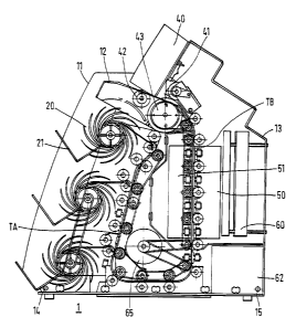
Figure 1 shows a schematic representation of an embodiment of inventive bank
note sorting apparatus 1 in the closed state. Bank note sorting apparatus 1
has three
parts 11, 12, 13. The three parts consist of middle, stationary part 12
surrounded by
removable, outer parts 11 and 13. In the area of one of outer parts 11 there
is input
pocket 40 in which the bank notes to be sorted are placed. Furthermore, three
like de-
posit devices 20, 21 for bank notes are located in said outer part 11. The
elements of
the uppermost of the three deposit devices 20, 21 are designated more closely.
Said
device has spiral stacker 20 and output pocket 21. In order to obtain a
compact struc-
ture of bank note sorting apparatus 1, the bank notes are processed in the
cross
i
CA 02394017 2002-05-31
-3- _ _
direction, i.e. the bank notes are transported along their cross fOr111at and
all processing
steps are effected along the cross format of the bank notes.
The compact design yields advantages with respect to ergonomic requirements
since apparatus 1 is therefore suitable for being operated by either a seated
or a stand-
ing user because input pocket 40 and deposit devices 20, 21 are within arm's
reach.
Bank note sorting apparatus 1 has operating device 30 having input unit 31,
dis-
play unit 32 and printer 33 as well as an interface or reading device 34 for
storage me-
dium 3 5: Input unit 31 and display unit 32 are used for controlling the bank
note proc-
essing apparatus during operation and for example selecting desired sorting
possibili-
ties. Storage medium 35 makes it possible for a user to identify himself as an
author-
ized user vis-a-vis apparatus 1. It is likewise possible for user-specific
operating
modes, settings or accounting data to be stored on storage medium 35, thereby
permit-
ting user-specific operation, or the use of the stored data on other
apparatuses. Storage
medium 3 5 can be for example a smart card or flash memory card with
corresponding
interface 34. Operating device 30 can be connected with bank note sorting
apparatus 1
by wire or wirelessly, e.g. by means of infrared or radio waves. The use of
external
operating device 30 results in an improvement particularly with respect to
ergonomic
requirements because operating device 30 is not firmly connected with
apparatus 1 so
that it is possible for a user to dispose operating device 30 in accordance
with his
physical requirements.
The three parts 1 l, 12, 13 of bank note sorting apparatus 1 form two outer
parts
11 and 13 and inner part 12, whereby outer parts 11 and 13 can be opened and
in the
closed state lie against inner part 12 along the contours designated A and B.
Figure 2 shows a schematic representation of bank note sorting apparatus 1 ac-
cording to Figure 1 in the open state. Outer parts 11 and 13 are swiveled away
from
inner part 12 and parts of the transport system transporting the bank notes
are visible.
The transport system consists substantially of two portions TA and TB which
are again
predetermined substantially by the contours designated A and B.
-4-
Figure 3 shows a section at right angles to the transport path of the bank
notes
through bank note sorting apparatus 1 according to Figure 1 in the closed
state, with
the three parts 11, 12, 13 and further elements.
It can be seen that singling device 41, 42, 43 with singling wheel 43,
retaining
wheel 41 and feed 42 is disposed under input pocket 40. Feed 42 has the
function of
transporting the individual bank notes of an applied bank note stack to be
singled to
singling wheel 43 and retaining wheel 41. Singling wheel 43 and retaining
wheel 41
can be designed for example as a friction wheel singler, it being ensured by
defined
ratios of fi-iction of singling wheel 43 and retaining wheel 41 that only one
bank note
at a time is grasped and passed on to first portion TB of the transport
system.
Portion TB of the transport system leads substantially through checking device
50, 51 for bank notes. Checking device 50, 51 is disposed on both sides of the
trans-
port system such that the bank notes transported along the transport path can
be
checked from both the front and back. Checking device 50, 51 is formed by two
sepa-
rate containers in which different sensors are disposed.
Figure 2 shows the basic structure of one of containers 50 of checking device
S0,
51. On the surface oriented toward the transport path, openings or windows 54
for the
sensors alternate with elements of the transport system. The elements of
transport sys-
tem 55 are formed for example by rubber rolls. This avoids the use of
transport belts
within checking device 50 so that the sensors can evaluate the total area of
the trans-
ported bank notes. The elements of transport system 55 are connected with
checking
device 50, 51 or the containers, resulting in easy replaceability of total
checking device
50, 51.
Figure 3 furthermore shows controller 60, for example a microprocessor with an
associated memory, that controls the sorting and deposit process in bank note
sorting
apparatus 1, in particular evaluating the signals from the sensors of checking
device
50, 5I . Further, power unit 62 for supply power to bank note sorting
apparatus 1 and
driving unit 65, e.g. an electric motor, for the transport system are shown.
CA 02394017 2002-05-31
CA 02394017 2002-05-31
_5_ _ _.
After checking device 50, 51 the bank notes are transported further from first
por-
tion TB to second portion TA of the transport system. The checked bank notes
are
deposited, under the control of controller 60, in the deposit devices disposed
along sec-
ond portion TA, the last of which in the direction of the transport path being
marked
by reference signs 20, 21. For this purpose, diverters present in the
transport system
are driven to guide bank notes to the particular deposit device in accordance
with the
result of the check and the sorting possibility selected by operating device
30.
Deflection of the transported bank notes after checking device 50, S 1 from
portion B
to portion A of the transport system gives rise to a trailing zone for the
bank notes.
This provides a greater time period for controller 60 to evaluate the signals
delivered
by checking device 50, 51, so that reduced efficiency (computer power or
storage ca-
pacity) of controller 60 is acceptable for performing the check of the bank
notes during
the resulting longer transport time of the bank notes.
Figure 4 shows a section at right angles to the transport path of the bank
notes
through bank note sorting apparatus 1 according to Figure 2 or Figure 3 in the
open
state.
In the representation, the two outer parts 11 and 13 of apparatus 1 are
swiveled
about axles 14 and 15. Axles 14 and 15 are fastened to baseplate 16 on which
middle;
stationary part 12 is also mounted. Middle, stationary part 12 retains its
position in the
open state. In middle, stationary part 12 motor 65 is disposed for driving the
transport
system by means of belts or toothed belts 2. It is likewise possible to use
toothed
wheels instead of the belts shown. Figure 4 indicates that only the element of
the
transport system disposed in middle, stationary part 12 is driven by means of
belts 2
directly by the motor. The elements of the transport system in outer,
removable main
parts 11 and 13 are driven by corresponding elements of the transport system
in mid-
dle, stationary main part 12 when apparatus 1 is closed. Driving energy can be
trans-
ferred by means of friction, e.g. by means of rubber rolls; or by means of
toothed
wheels.
Figure 4 also indicates that the elements of transport system 55 within
checking
device 50, 51 are connected firmly therewith. Replacement is thus readily
possible, as
CA 02394017 2002-05-31
-6-
described above. This also holds for container 51 of checking device 50, 51,
said con-
tainer being located in middle, stationary part 12 of apparatus l, since the
elements of
the transport system of container 51 are only tied into the drive of the
transport system
by means of two belts 2.
Further, Figures 3 and 4 indicate that the transition along the transport path
of the
transport system from portion TB to portion TA is designed so as to form only
a short,
readily accessible transition area from which any faultily transported bank
notes can be
removed without problems. In order to improve accessibility further, an axle
can also
be provided in the area of baseplate 16 for inner part 12, about which the
middle part
can be swiveled. This permits the portion of the transport system between
baseplate 16
and inner part 12 to be readily accessible as well.
Described bank note sorting apparatus 1 has the advantage that in particular
the
transport path of the bank notes along critical devices, such as singler 41,
42, 43,
checking device 50, 51 and deposit device 20, can be opened, so that any bank
note
jams that occur can be removed without problem. The use of only one swivel
axle 14,
15 for each of portions TA, TB of the transport system results in a mechanical
struc-
ture that has the advantage of making areas accessible along the transport
system that
are very easily surveyed and can be opened wide for troubleshooting or
maintenance.
Instead of swivel axles, 14, 15 one can use rails or the like on which outer
parts 1 l, 13
can be removed by shifting middle part 12.
In order to recognize faultily transported bank notes one can use sensors, for
ex-
ample light barriers, that are disposed along the transport system. Suitable
places for
such sensors are before or after the individual devices of bank note
processing appara-
tus l, namely singling device 41, 42, 43, checking device 50, 51 and the
deposit de-
vices or the above-described diverters in the transport system. If faulty
transport is
recognized by the sensors, it can be indicated for example on display 32 of
external
operating device 30 which of removable, outer parts 11 and/or 13 should be
opened for
eliminating the error. This avoids unnecessary opening of one of parts 11 and
13. It is
likewise possible to provide a display, e.g. a light-emitting diode, on outer
parts 11 and
CA 02394017 2002-05-31
_ 7 _
13 far indicating part 11 and/or 13 to be opened. The sensors for recognizing
faulty
transport are evaluated by controller 60 which drives the display accordingly.
Further displays can be provided for the three output pockets for indicating
when
a predetermined maximum number of bank notes has been deposited in the
particular
output pocket since said output pocket is otherwise no longer available for
further
processing. The displays can be located directly on the output packets or the
display
can be effected on display 32 of external operating device 30. The full
display is
driven by controller 60 when a sensor in the particular output pocket signals
that the
maximum number of bank notes has been deposited. The maximum number of bank
notes to be deposited can also be determined by controller 60 by the latter
counting the
bank notes deposited in an output pocket during processing until a presettable
variable,
e.g. 100 bank notes, is reached. After removal of the bank notes by a user,
which can
be determined e.g. liy evaluation of the particular sensor in the particular
output pocket
by controller 60, the particular output pocket is available again for
receiving further
bank notes, thereby permitting altogether faster processing of the bank notes
to be proc-
essed.