Note: Descriptions are shown in the official language in which they were submitted.
u,
CA 02394388 2002-06-14
WO 01/43936 PCT/EP00/12503
A METHOD FOR PRODUCING MOLDED ARTICLES AND A DEVICE FOR
CONDUCTING THIS METHOD
The invention concerns a method for producing a molded article having a
visible side and
a back side from a hardenable reaction compound, where a casting mold is put
together from
several mold parts into a configuration that essentially does not change
during the casting and
hardening step and that forms a cavity into which the reaction compound is
filled and hardened,
after which the mold is opened and the molded article is removed.
The invention additionally concerns a device for conducting such a method.
One problem that must be considered and taken into account in the manufacture
of the
molded articles from hardenable reaction compounds described above is that
during the
hardening or polymerization process a reduction of volume (shrinkage) of the
polymer material
occurs, which is particularly extensive when using polyacrylic- or
polymethacrylic-based
reaction compounds.
In order to avoid the formation of defective surfaces, which make the molded
article
unsellable, care must be taken at least that the still unhardened molding
compound is
continuously in contact with at least the visible side surface of the mold.
Various measures have previously been recommended for obtaining, in some
cases,
practically perfect visible side surfaces, but which still have various
disadvantages from the
standpoint of the overall process of producing molded articles.
On the one hand, it was recommended that the reaction compound be allowed to
stand
under filling pressure during the polymerization or hardening step (dwell
pressure process), i. e.,
the connection of the cavity of the mold to the supply tank that contains the
hardenable molding
compound is left under filling pressure during at least a specific period of
time in the
polymerization process, so that in principle the volume reduction caused by
shrinkage of the
molding compound initially introduced into the mold can be compensated by an
additional
supply of fresh quantities of the reaction compound. The success of this
measure is, on the one
hand, dependent on the actual shape of the molded article and is frequently
difficult to conduct
successively, especially in the case of flat objects with low wall thickness
such as kitchen sinks,
since gelation of the reaction compound takes place at first during the
polymerization process,
which makes the additional delivery of fresh reaction compound more difficult.
On top of that,
this can lead to undesirable delays of the hardening operation, since the last
supplied proportions
of fresh reaction compound require additional time in order to harden
completely. Other common
m
CA 02394388 2002-06-14
2
related problems are an insufficient bond between subsequently injected
portions of the reaction
compound and the originally injected reaction compound and problems in
demolding.
The edges of a flat product with low layer thickness, as is the case, for
example, with
kitchen sinks, present particular problems with the additional feed of
material.
A proposal for an alternative solution was to use a mold whose mold parts can
be forced
together under pressure during the polymerization process, so that the volume
of the mold cavity
decreases during the polymerization process (see EP 0019867). With this the
shrinkage that
occurs is compensated at least at the flat parts of the mold that extend
perpendicular to the
clamping direction. This method requires that the two mold halves be arranged
in telescoping
fashion and in the edge region be sealed with an elastic seal that is
deformable as the parts are
pressed together. The disadvantage with this method lies in the fact that a so
called casting edge
also has to be cast, which stretches from the actual mold edge to the seal,
which is situated at a
higher level. The presence of the casting skin results in costly secondary
machining, which
clearly increases production costs.
The casting skin could be reduced only if the mold halves in their edge
regions lie firmly
against one another from the start, which however again keeps them from moving
closer together
during the polymerization step and thus being able to cause a reduction of the
extent of volume
shrinkage. For this case only the previously discussed dwell pressure method
has been available
up to now.
EP 0 354 017 A2 gives a method for casting polymerizable organic liquids in
which a
mold surface has a flexible membrane of a thermally conductive elastomer. The
flexible
membrane encloses a cavity, in which there circulates a liquid under pressure,
which can be
heated to harden the polymerizable organic liquid.
The objective of the invention is to make available a generic method that
overcomes the
disadvantages of the prior art, in particular to improve a method for
producing a molded article
as claimed at the start so that the molded articles can be obtained with
minimum cost for
additional processing and that the method can be carried out simply and
cheaply over a long
period of time.
This objective is solved by the fact that a deformable mold surface that is
formed from a
metal ply is used and that the metal ply is kept in contact with the reaction
compound in the
deformation of the deformable mold surface.
With this method the edge regions of the molds are positioned directly on one
another
from the start, so that the development of a casting skin can be avoided.
Through the use of a
deformable mold surface to reduce the volume of the mold cavity, the
possibility is now created
of compensating the volume loss due to the shrinkage of the polymer material
during the
hardening step, namely not only perpendicular to the direction of clamping of
the mold, but also,
CA 02394388 2002-06-14
if desired, three dimensionally, i.e., essentially on all sides, and the
deformable mold surface
essentially makes up the back surface of the mold that forms the molded
article. Through
different deformability different regions of the moldable mold surface regions
in which higher
shrinkage is expected can be more deformable than other regions in a tailored
manner if
3
necessary.
Preferably, a deformable mold surface that is elastically deformable is used,
so that after
the end of the hardening operation and after demolding the defomlable mold
returns to its
original shape and thus can be reused. Alternatively, especially if there is
the possibility of using
cheap deformable mold surfaces, one can specify the use of plastically
deformable mold surfaces
which then can in each case be used just once for a casting operation. If the
mold back side does
not have greater importance for the appearance of the product, the mold
surface could then be
left on the actual molded article as a lost element.
The latter is particularly conceivable when the deformable mold surface is
formed of a
plastic ply.
Preferably, the deformation of the deformable mold surface is produced
pneumatically or
hydraulically, by injecting a liquid or gaseous pressurizing medium into the
space between the
mold surface and an accompanying support form.
Since the problem of shrinkage can be solved by deforming the mold surface and
thus
reducing the volume of the mold with the method in accordance with the
invention, it becomes
possible to separate the reaction compound in the mold from the supply vessel
after filling the
mold, i.e., the molding compound in the supply vessel does not need to
continue to remain
connected to the compound in the mold.
Preferably, the deformable mold surface will form the back side of the molded
article, so
that slight variations in the surface quality or possible deformations
occurring differently over
the surface can be accepted without disadvantage to the appearance of the
molded article. This
allows in particular the use of very thin deformable mold surfaces, and in
particular the use of
plastically deformable mold surfaces that can optionally remain on the molded
article as a lost
element.
Preferably the mold parts are assembled with edge regions lying one directly
on the other,
with a seal preferably being laid between the edge regions.
The lying of the edge regions on top of each other leads to the molded article
having a
definite edge, without having to provide a seal to prevent the escape of
portions of the molding
compound in every case. In contrast, it can be desirable for highly fluid
components of the
casting compound (especially excess monomer) to be able to escape from the
mold or the mold
cavity in the edge region, so that, for one thing, it is possible for this
excess material to drain off,
CA 02394388 2002-06-14
and, of course, at the same time so that it is also possible to deaerate the
mold through these
overlying edge regions during the filling of the mold.
4
In order to avoid uncontrolled escape of monomer it is also possible to add a
seal between
the edge regions, as noted earlier. It is preferably laid into a groove, so
that the edge regions can
nevertheless be in contact with each other. The groove with the positioned
seal then seals the
mold as a whole from the surroundings, besides sealing the superimposed edge
regions.
A traditional O ring made of an elastomer that is resistant to the reaction
compound can
be used as sealing material. Alternatively, however, one can also use a felt
material, which on the
one hand keeps the deaeration function of the mold in effect, but on the other
hand traps liquid
portions (especially excess monomer) escaping from the cavity of the mold, end
keeps the
surroundings of the mold from becoming contaminated.
In many cases it is possible to eliminate all other forms of deaeration when
using a felt
seal. Preferably a hollow space or groove running all the way around is
provided in the edge
region of the mold, in the direction toward the mold cavity from the sealing
groove, in which the
excess monomer that flows between the superimposed edge regions can be
collected. By
specifying the volume of the groove (hollow space) the settling of the filler
can be controlled,
where again the products will largely have very little or no distortion. This
groove or hollow
space is preferably arranged between the circular seal and the contact line of
the edge regions,
i.e., the regions in which the mold parts lie directly on each other and the
mold cavity is initially
sealed.
In the production of molded articles that have a basin shape with a drain a
connecting
piece to make a flow connection to the supply vessel containing the hardenable
reaction
compound is arranged preferably in the region of the molded article that
includes the drain.
Alternatively, or in addition, a connecting piece for making a flow connection
to the
supply vessel containing the hardenable casting compound can also be made at
points in the
molded article at which greater thickness is required, for example, at clamp
lugs for securing the
molded article at a work place or for other purposes, so that molding
compound, which akeady
contains considerable amounts of inorganic fillers, flowing into the mold does
not lead to
abrasion of the opposite mold surface as it flows into the mold.
In the regions of the molded article in which a through-hole is to be made
subsequently,
the mold is preferably designed so that the mold surfaces of the visible and
back sides can be
positioned to have a minimum spacing between them during the hardening
operation.
With the mold in accordance with the invention the spacing of the mold
surfaces during
the filling of the mold can initially be much larger and thus enable exact
filling of all of the mold
regions and only upon deforming the deformable mold surface does the mold take
on the desired
minimum spacing in order to form the predetermined breaking line.
CA 02394388 2002-06-14
In this way very thin wall thicknesses arise in the regions of the molded
article that are to
be broken later and the separation can be produced by simply hitting the
molded piece with a
rubber hammer or the like. Here it is recommended in particular that the
regions for the
through-holes be designed so that the mold surfaces along a substantially
closed line can be
positioned essentially next to each other.
The invention additionally concerns a device a for carrying out the said
method, where
this device is characterized by the fact that it consists of a mold that can
be assembled from
several parts, which forms a cavity that can be filled with the reaction
compound, where at least
one mold part has a support form and a mold surface formed at least areawise
separately from it,
and that the separately formed mold surface is arranged to be deformable
and/or moveable in
order to reduce the volume of the cavity that is to be filled with the
reaction compound.
The mold in accordance with the invention creates the possibility of producing
molded
articles, especially molded articles that have complicated shape such as a
kitchen sink with
several basins and a drain surface, with a visible side and a back side that
is essentially improved
in appearance, where the cost for additional machining of the molded article
is considerably
reduced compared to the molded articles that could be produced up to now.
This is achieved in particular by a reduction of volume or a compensation of
volume
during the polymerization phase through deformation of a mold surface region,
for example the
back side half of the mold. This mold half or its surface is made preferably
of an elastic material,
for example, nickel in thin sheet form, stainless steel sheet or plastic.
The deformable mold surface can either remain as a lost element (especially in
the form
of a cheap plastic part) on the product or can be reused and form a permanent
part of the mold.
Preferably, the part of the mold that constitutes the deformable mold surface
consists of a
protective form of glass fiber reinforced plastic and a thin nickel sheet mold
surface that is
elastically deformable. The volume reduction in the cavity of the mold is
achieved through a
liquid pressurizing medium that is forced or injected into the intermediate
base between the
support form and the thin nickel sheet mold surface. Channels are preferably
provided in the
support form surface for uniform distribution of the pressure and regulation
of the direction of
flow of the pressurizing medium.
The two mold halves preferably lie flat on each other, metal to metal. The
sealing surface
that is thus formed should be very evenly and precisely matched in order to
minimize additional
machining. Nevertheless, an absolute seal cannot be achieved by laying metal
on metal. For this
reason a groove for holding an additional seal (for example an O ring) is
provided with a spacing
between it and the mold cavity. Instead of an O ring of an elastomer that is
resistant to the
hardenable reaction compound, it is also possible to use a felt material,
where this offers the
CA 02394388 2002-06-14
advantage of permitting deaeration of the mold during filling. In this case
another mode of
deaerating of the mold can possibly even be entirely omitted.
The filling points of the mold are situated either at a drain opening of the
basin or at a so
6
called clamp lug. Filling at sites that lie opposite the visible side of the
mold is not
recommended, since the reaction compounds that are used contain high amounts
of inorganic
fillers, which after only a few fillings can leave behind abrasion marks on
the visible side of the
surface of the sink. These will be visibly reflected on the surface of
subsequently produced sinks.
The insufficient tightness of the mold halves lying metal to metal is quite
useful, since
this insufficient seal allows excess monomer to drain from the mold. This
allows the settling of
the filling to be controlled and through this the products will have very
little or no distortion. In
order to make operation with such molds more agreeable and to avoid fouling
the environment
with monomer, a circumferential hollow space is provided, preferably in the
edge region of the
molds, to collect excess and escaping monomer.
Finally, besides this circular hollow space, a circular sealing band can be
provided, as
already described.
An important advantage of the device or the method in accordance with the
invention lies
in the fact that compensation for shrinkage takes place not only two
dimensionally, as is possible
when the mold halves are moved together, but rather, three dimensionally so to
speak, since
through an all-sided stress on the deformable mold surface in each direction
space a deformation
may be achieved and in this way it is possible to check shrinkage wherever it
in fact occurs
during hardening. Compression or shifting of portions of the reaction compound
that have
already gelled in the mold is largely avoided in this way.
In the end these advantages result in a better, i.e., smoother and more
uniformly made,
back side of the molded article being obtained.
Moreover, the weight of the product can be maintained with considerably more
precision
than up to now, since one can operate with a precisely set amount of reaction
compound and no
additional material has to be additionally supplied to compensate shrinkage.
In this way there is
also the possibility of reducing the wall thicknesses of the molded article
and saving the material
that up to now was added for reasons of safety due to the high variations of
weight and wall
thickness in an individual molded article.
These and other advantages of the invention are illustrated in more detail
below by means
of a drawing. It shows in detail:
Figure 1: a lengthwise section through a device in accordance with the
invention;
Figure 2: a section along line II-II in Figure 1;
Figure 3: a detailed view from the sectional representation of Figure 1; and
Figure 4: a top view of the device of Figure 1.
CA 02394388 2002-06-14
7
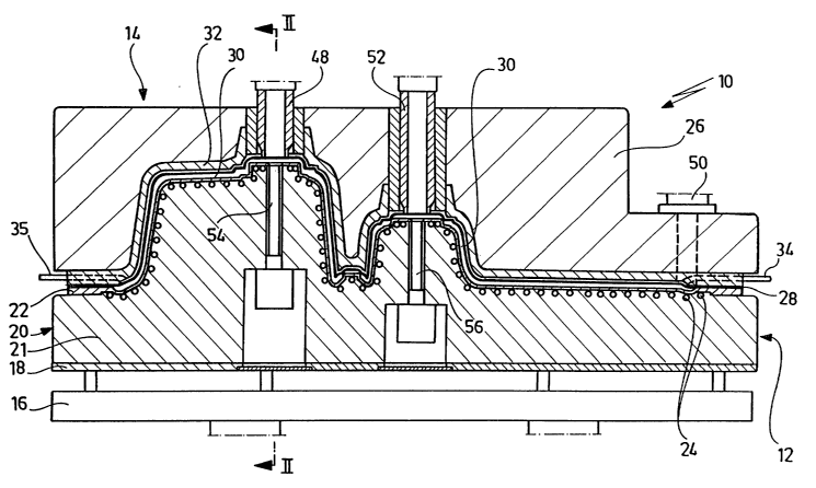
Figures 1 and 2 show a mold, designated as a unit by the reference number 10
and having
a mold bottom part 12 and mold top part 14. The mold bottom part 12 is formed
of a frame 16
and a plate 18 supported on this frame and includes a lower support from 20,
which is designed
as the positive form for producing a kitchen sink and which has on its upper
side a covering with
a thin nickel pan 22, which is heatable from its back side by means of a
conduction system 24.
The cavity remaining between plate 18 and nickel pan 22 is filled with sand in
order to guarantee
uniform transfer of pressure. A heating fluid is circulated through conduction
system 24.
The mold top part has an upper (negative) support form 32, which carries on
its surface a
thin nickel pan 28. The cavity 26 remaining on the back side of support form
32 is filled with
sand.
The nickel pans 22 and 28 form the surfaces of the mold cavity 30, where
nickel pan 22
forms the visible side of the kitchen sink and nickel pan 28 the back side.
The support form 32 of the mold top part 14 is essentially made of glass fiber
reinforced
plastic.
The nickel pan 28 is held in its assembled state at a small distance from
support form 32
of the mold top part 14, which distance is essentially uniform over the
overall surface of nickel
pan 28 or the surface of the support form 32.
The resulting cavity is connected to supply pipes 34 and 35, which are
connected to a
hydraulic unit (not shown).
A liquid pressurizing medium is forced through connecting pipes 34 and 34 into
the
intermediate space between the support form 32 and the nickel pan 28 and in
this way the
distance between support form 32 and nickel pan 28 can be varied, so that it
is possible to vary
the volume of the mold cavity 30 according to the fixed position of the mold
top and bottom
parts relative to each other.
Figure 3 shows an enlarged section from Figure l, in which the formation of
the surfaces
of the parts of mold 10 can be seen in detail.
The arrangement of pipe 24 for the temperature-controlling liquid directly
adjacent to
nickel pan 22 of the bottom part of the mold, which thus guarantees the
temperature control of
the visible side surface of the mold, can clearly be seen.
The deformable mold surface that forms the back side of the molded article is
formed by
nickel pan 28, which implements the deformable mold surface of mold 10 in
accordance with the
invention.
Channels 38, with rectangular cross section, which allow essentially uniform
supply of
pressurizing medium to the back side of nickel pan 28 in order to enable an
essentially uniform
reduction of the volume 30 are recessed in support form 32. Channels 38 in the
end are
vo
CA 02394388 2002-06-14
8
connected to supply pipes 34 or 35 (not shown in Figure 3) and allow control
of volume 30
during the overall polymerization process.
In the edge region the mold parts 12 and 14 lie flat on each other, as is
visible in
particular in Figure 3. In the edge, which is kept relatively broad here,
where flat seating of
nickel pan 28 on nickel 22 occurs, there is a groove 40 provided, which
accepts a sealing ring 42,
which here guarantees that mold 10 will be sealed off from the environment.
Inward from seal 42, the edge region of the mold part 12 contains another
groove 44,
which remains unoccupied and thus forms a hollow space for monomer escaping
from the mold
or the mold cavity 30.
In order to design the additional machining of the finished molded article to
be as simple
as possible, it is of elementary importance that the edge regions of mold
parts 12 and 14 are
machined very accurately and are able to take up an exactly flat position with
respect to each
other. Because of this, at most a fish skin like progression of the polymer
compound can form
from edge 46 of the molded article, which can be taken care of by simple means
and without
great expenditures of time. In contrast to this, with the previously preferred
technology, in which
the upper part 14 was moved toward the under park 12 during the polymerization
process, it was
necessary to mill off the extension (casting edge) formed at the casting edge,
which meant
considerable expenditure of time and money.
Finally, Figure 4 shows a top view of the mold 10 in accordance with the
invention, in
which it becomes clear that preferably several connections 34 an 35 are used
in order to supply
the pressurizing medium to the mold uniformly distributed over the deformable
mold surface.
A filler connection 48, which is fitted with a stopcock (not shown).
Deaeration of the
mold can take place via the mold edge, if a gas permeable sealing material is
used in groove 42.
If the gas permeability is insufficient or if a gas-tight sealing material is
used in groove 42, then a
deaeration connection 50 becomes necessary, which is arranged in a corner
region of the sink. In
the filling of the mold this connection is tipped so that the corner region
provided with the
deaeration connection 50 forms the highest point and thus complete filling of
the mold is
guaranteed.
After hardening the casting compound or reaction compound the mold top part 14
is
lifted from bottom part 12 and the molded article remaining there (kitchen
sink) by pneumatic
cylinder 52. In another step the molded article is then lifted from the mold
bottom part 12 with
the aid of other pneumatic cylinders 54 and 56 and then removed from mold 10
for further
processing.
Because of the use of the mold in accordance with the invention, the further
processing
consists of only a few and non-time consuming steps. For one thing, the
discharge sites of the
mold are easily knocked off by hand or with a rubber hammer, since these are
delimited from the
CA 02394388 2002-06-14
9
remaining molded article by thin wall regions (intentional breakage sites).
The edge of the sink
needs only be lightly hand sanded, so that the remains of the fish skin formed
during hardening
are removed.