Note: Descriptions are shown in the official language in which they were submitted.
CA 02394560 2002-07-24
TITLE OF INVENTION
LOG MERCHANDISER
TECHNICAL FIELD OF THE INVENTION
This invention relates to a log merchandising apparatus.
BACKGROUND OF THE INVENTION
Log merchandisers process tree-length logs into shorter lengths for further
processing. It is desirable to process the logs as quickly as possible, with
as little wasted
wood as possible.
One prior art log merchandiser is disclosed in U.S. Patent No. 6,305,259,
issued to
Whitworth. Whitworth discloses a log processing system whereby logs are
transported
via a series of conveyor belts, through a singulator and scanner, and into a
cradle
assembly that holds the logs while pivoting adjustable saws cut them. The saws
and the
log cradles are both mounted on saw boxes. The entire saw box moves laterally
on wheel
assemblies on floor-mounted guide rails. Each saw box, along with its
associated saw
and log cradle, is positioned along the length of the log prior to placing the
log in the log
cradle.
Hydraulic cylinders move the saw boxes to their proper positions, as
determi.ned
by digital probes. Accordingly, the length of the hydraulic cylinders
detennines the travel
distance of the saw assemblies. No saw can travel farther than the length of
the piston
rod in the hydraulic cylinder. Even if a long hydraulic cylinder is used, no
adjacent saws
may move closer together than the distance determined by the substantial width
of the
1
CA 02394560 2002-07-24
saw box. This limits the length of log segments that can be cut. It also
limits the length
of logs that may be processed by the apparatus.
Other examples of travelling saws are disclosed in the prior art. U.S. Patent
No.
5,179,883 to Payr discloses a saw carriage supported on guide rails on a floor-
mounted
frame. A motor-driven rope pulley, supported by guide rollers attached to the
frame,
drives the saw carriage laterally. Another travelling saw is described in U.S.
Patent No.
4,330,019 to Murphy. In this system, each saw rests on a floor-mounted
carriage fitted
with wheels that ride on rails. A pinion, rotated by a motor mounted on the
saw carriage,
extends out of the bottom of each saw carriage. The pinion meshes with a rack
secured to
one rail to move the saw carriage along the length of the apparatus. A similar
travelling
saw system is disclosed in U.S. Patent No. 6,279,441 to Streblow.
In the case of each of the prior art systems described above, the saws are
mounted
on relatively bulky apparatus mounted on the floor adjacent the log delivery
system. This
makes it difficult or dangerous for personnel to move about the merchandiser,
for
example to clean or maintain it. In addition, the rail mounted saw assemblies
that
characterize the prior art require powerful drives to move the significant
weight of the
assemblies. This limits the accuracy and speed at which merchandising can take
place.
There is therefore an advantage to moving the travelling saw assemblies in a
log
processing system off the floor, to a point above the log delivery system. One
example of
an overhead saw assembly is U.S. Patent No. 5,142,955 to Hale, which discloses
a
travelling trim saw carried on an aluminum and low-friction plastic carriage
slidably
supported on an overhead box beam. Hale's carriage travels laterally
approximately two
feet under the control of a servomotor, which connects to a toothed pulley
engaged with
an endless belt supported by another toothed pulley. Another overhead saw
system is
described in U.S. Patent No. 4,262,572 to Flodin, wherein the saw carriage,
containing
2
CA 02394560 2002-07-24
one main saw and two horizontal saws, is supported on guide wheels that run
along an
overhead track. U.S. Patent No. 4,960,023 to Reuter discloses a third overhead
saw
system, wherein two sliding saw carriages, each containing a plurality of
saws, are
suspended on an overhead guide support. Upper and lower guide rolls, or other
sliding
guide elements, are used to support the saw carriages as they move along the
guide
support. The saw carriages are positioned with hydraulic cylinders fastened to
the guide
support stand.
These overhead travelling saw systems move parts of the log processing
apparatus
off the floor. However, the systems do not allow for a plurality of
independently movable
saws. In addition, the beams supporting the saws often restrict how far the
saws may
move in the lateral direction. Therefore, the length of logs that can be
processed and the
length of the cut logs are limited. This limits the efficiency of the log
processing system.
It is an object of the present invention to increase the speed and efficiency
of a log
merchandiser. It is a further object of the present invention to reduce the
complexity,
weight and floor space required for the saw assembly and to provide a saw
assembly that
is highly accurate and versatile.
These and other objects of the invention will be appreciated by reference to
the
summary of the invention and to the detailed description of the preferred
embodiment that
follow.
SUMMARY OF THE INVENTION
One aspect of the invention is the provision, in a log merchandising system,
of
truss-mounted overhead travelling saws that pivot downward to cut the log.
3
CA 02394560 2002-07-24
In a more specific aspect, the invention further comprises a rack and pinion
drive
assembly for displacing the saws laterally along the length of the log. The
displacement
drive motor may be mounted directly on the carriage, which also includes the
saw motor.
In yet a further aspect, the invention comprises the use of a lineal bearing
assembly for facilitating lateral displacement of the saws.
In yet another aspect, the invention comprises a log feeding apparatus to
ensure
that logs are fed individually, a log holding apparatus, and overhead truss-
mounted
travelling saws.
The saws are mounted on an overhead truss, positioned slightly forward of the
cutting area, and pivot down toward the log in order to make their cuts. The
overhead
saw assembly moves machine components off the floor and above the log holding
apparatus, reducing the amount of floor space required for the apparatus and
making it
easier for workers to move around the merchandiser when the saws are not in
use.
The use of a rack and pinion drive assembly according to the invention allows
the
entire saw system to be much smaller than prior art merchandisers wherein each
saw is
mounted on an independent large box assembly.
In one aspect, the invention is a log merchandiser comprising a log
positioning
stage to establish placement and orientation of a log and support a log in a
stationary
position in a cradle assembly having a longitudinal axis; an elongated
overhead truss
extending above said cradle assembly parallel to said longitudinal axis; and a
plurality of
pivoting saw assemblies mounted for lateral travel along said overhead truss,
said saw
assemblies comprising a pivoting saw blade selectively extendible to said
cradle
assembly.
4
CA 02394560 2002-07-24
In a further aspect, the saw assemblies travel laterally along said truss on a
rack
and pinion drive.
In yet a further aspect, the log merchandiser comprises lineal bearing
assemblies to
support the saw assemblies on the overhead truss.
In a more specific aspect, each pivoting saw assembly comprises a circular saw
pivotally mounted on a saw arbor; a motor to operate the saw; and a motor to
actuate said
pinion so as to move the saw assembly along the overhead truss.
In a further aspect, the invention comprises a gear system, connected to the
motor
that actuates the pinion, to allow lateral movement of said saw assembly and a
lateral
displacement control system to control the lateral movement of said saw
assembly.
In yet a further aspect, the invention comprises a frame to support said
travelling
saw assembly components on said truss and a bearing assembly to support said
frame on
said truss. More specifically, the gear system is a rack and pinion gear
system,
comprising a vertically mounted reducer, a spur rack and a spur gear engaged
with said
spur rack. The support frame comprises two vertical L-shaped plates joined by
a
horizontal plate connected to the long sides of each of said L-shaped plates,
and further
comprises support shelves extending from the short sides of each of said L-
shaped plates
underneath said horizontal plate.
The bearing assembly connects said horizontal plate to said overhead truss and
comprises at least one linear roller bearing and at least one linear bearing
guideway which
interlocks with each said linear roller bearing. In the preferred embodiment
of the
invention, the bearing assembly comprises four linear roller bearings, each
mounted on a
5
CA 02394560 2002-07-24
corner of the uppermost side of said horizontal plate. Further, the preferred
embodiment
comprises two linear bearing guideways, mounted on the lowermost side of the
overhead
truss, each linear bearing guideway interlocking with two of said linear
roller bearings.
In a further aspect, the log merchandiser comprises at least one stationary
circular
saw mounted on the overhead truss.
In yet a further aspect, the invention may comprise a mechanism to align an
end of
the log with said reference line. Such mechanism may comprise a piston pushing
one end
of said log.
The foregoing was intended as a broad summary only and was not intended to
define the limits or requirements of the invention. Other aspects of the
invention will be
appreciated by reference to the detailed description of the preferred
embodiment and to
the claims.
BRIEF DESCRIPTION OF THE DRAWINGS
The preferred embodiment of the invention will be described by reference to
the
drawings in which:
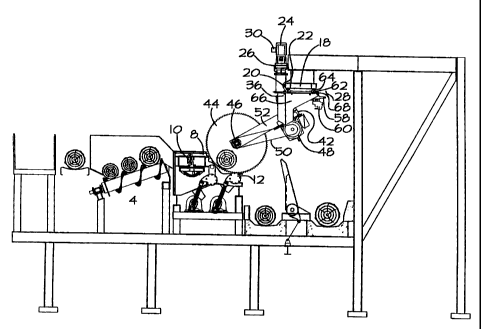
Fig. 1 is a front view of the preferred embodiment of the invention;
Fig. 2 is a side view of the preferred embodiment;
Fig. 3 is a side view of an overhead saw assembly according to the preferred
embodiment;
6
CA 02394560 2005-04-26
Fig. 4 is a front view of the overhead saw assembly shown in Fig. 3;
Fig. 5 is a side view of the vector motor assembly, with the spur rack and
pinion
drive assembly and overhead truss shown in section along line 5-5 of Fig. 4
according to a
preferred embodiment;
Fig. 6 is a side view of the saw blade and pivot platform without the lineal
travel
frame;
Fig. 7 is an enlarged view of one lineal bearing assembly that supports the
lateral
movement of the travelling saws;
Fig. 8 is a side view of the lineal travel frame, on which the travelling saws
are
supported; and
Fig. 9 is a front view of the lineal travel fiame of Fig. 8.
DETAILED DESCRIPTION OF THE PREFERRED EMBODIMENT
OF THE INVENTION
In the preferred embodiment of the log merchandiser of the invention, a log is
selected out of a pile with a singulating device. The log is debarked and
scanned to
determine defects, diameter, sweep and length. The scan enables optimization
software
to determine the optimal cuts to maximize the value from the log. At the end
of the scan
cycle, the log is carried on conveyor belts to the infeed of the log
merchandiser where it is
7
CA 02394560 2002-07-24
pushed by an array of log pushers onto the bottom flight of a log feeding
apparatus 4, as
shown in Fig. 1.
The log feeding apparatus 4 of the log merchandiser 2 can take several forms.
It
may be a spiral log feeder of the type disclosed in applicant's co-pending
U.S. Patent
Application No. 09/997,379, which is the embodiment shown for reference in
Fig. 2.
Alternatively, the log may be fed by a quadrant log feeder of the type
disclosed in U.S.
Patent No. 5,119,930, issued to Stelter, a stepped singulating and ending
device, as
disclosed in U.S. Patent Nos. 5,257,688, issued to Fridlund or 5,174,351,
issued to
Lindenblatt et al, or an assembly comprising one or more endless conveyor
belts
conta.ining protrusions which act to carry individual logs forward and up
toward the saws.
The invention also contemplates using some of these log feeding apparatus in
series, one
feeding into the next. In general, the main concern in feeding logs through
the log
merchandiser 2 is to ensure the logs move through at a consistent maximum
speed, being
presented to the saws for cutting at an optimal rate without overwhelming the
saws.
Therefore any combination of log feeding apparatus 4 may be used. It is also
possible to
eliminate the log feeding apparatus completely, if the log holding apparatus
of the next
stage can properly carry out this feeding function.
Once a log reaches the top of the log feeding apparatus 4, it drops over the
top
edge and enters the first stage of the log holding apparatus 8. In the
preferred
embodiment shown in Fig. 2, the log holding apparatus is a two-stage log
ladder of the
type disclosed in U.S. Patent No. 5,423,417, issued to Redekop, but any
apparatus capable
of advancing the log and properly presenting it to the saws for the cutting
cycle may be
used. The main requirements for selecting a log holding apparatus are that
each log must
be advanced individually and then held securely at the correct elevation for
the saws to
descend in the cutting cycle. Therefore, any apparatus with a secure log-
holding cradle
may be used to present the log to the saws for the cutting cycle. Apparatus
that contain
8
CA 02394560 2002-07-24
clamps to hold the log securely may also be used, but are not preferred, as
the clamps may
interfere with the cutting path of the saws.
It may also be preferable to be able to push the log laterally, such as with a
piston,
in order to line up the log for an end trim cut. In the preferred embodiment,
one end of
the log is lined up with a fence line as the log enters the first stage of the
log holding
apparatus 8. If the initial scan has determined that no cut is required to
square up the log,
a piston 10 extends through the fence line to push the log laterally such that
its end is
away from the "0" line, a reference point determined by the cutting path of
the stationary
"O" saw. The first stage of the log holding apparatus 8 then advances the log
into the
second stage of the log holding apparatus 12. If the log does need trimming,
the piston 10
pushes the log such that the log is properly aligned relative to the "0" line
before the log
passes on to the second stage of the log holding apparatus 12.
The second stage of the log holding apparatus 12 presents the properly aligned
log
and securely holds it in place so that the overhead saws 14 can pivot downward
to make
their cuts through the log. If the end of the log is not square, it will be
trimmed. The trim
cut, if required, will always be made at the "0" line by the "0" saw 16 (shown
best in
Fig. 1). The "0" saw 16 is mounted on the underside of an overhead truss 18,
forward of
the second stage of the log holding apparatus 12. The "0" saw 16 pivots down
onto the
log (not shown in Fig. 1) to complete a cut and then retracts up out of the
way so the
second stage of the log holding apparatus 12 can safely eject the log segments
onto an
outfeed conveyor belt. The end of the log severed by the "0" saw 16 falls
through a gap
on the log cradle between the fence line and the "0" line.
All other cuts are made with travelling overhead circular saws 14, shown in
more
detail in Figs. 3 and 4, which pivot into and out of the cutting area in the
same cutting
cycle. The travelling saws 14 are also mounted on the overhead truss 18, on a
linear
9
CA 02394560 2005-04-26
guidance system. The preferred embodiment of the log merchandiser 2 consists
of four or
five travelling saws 14 plus the "0" saw 16. This embodiment is capable of
processing
logs up to 60 feet in length. Use of more travelling saws 14 and a longer
overhead truss
18 would allow processing of longer logs.
The following description applies to the mounting and driving assembly for one
of
the overhead travelling saws 14. Each travelling saw 14 moves reversibly and
independently along the length of the log on a rack and pinion drive
comprising a spur
gear 20 which engages a rack 22 mounted on the overhead truss 18. The drive
assembly
for the lateral movement of each saw, best shown in Fig. 5, is mounted on the
top side of
the overhead truss 18 and consists of a vector motor 24 directly connected to
a vertically
mountedreducer 26. A vector motor 24 is preferred for this application because
it offers
fu11 feedback and control of the motor operation. The motor operating speed is
directly
linked to the movement of the saw carriage 28 along the overhead truss 18, in
that the saw
carriage 28 travels exactly 1.9 inches for each revolution of the motor. The
vector motor
24 also offers electric braking for rapid stops. The vector motor 24 will ramp
up from 0
to 48 inches per second (or down from 48 to 0, in the case of braking) in half
a second.
Computer control of the vector motor 24, through the control box 30, allows
precise
control of overhead saw 14 travel. Once the saw 14 is properly positioned for
an optimal
cut of the log, the vector motor 24 stops running and the saw carriage 28
movement
immediately stops.
Referring again to Figs. 3-5, a shaft 32 depending from the vertically mounted
reducer 26 rotates a spur gear 20. The spur gear 20 engages a spur rack 22,
mounted on
the overhead truss 18, thus driving the travelling saw 14 laterally along the
overhead truss
18. Piloted flange bearings 34 support the shaft 32. This type of bearing is
preferred
because it allows the proper alignment of the supporting plates 38 on the top
and bottom
of the shaft assembly. This in turn ensures the spur gear 20 and rack 22 are
properly
CA 02394560 2005-04-26
aligned and that the lineal travel frame 36 is mounted properly, reducing the
chances that
the saw camage 28 will malfunction because of unbalanced wear on weight-
bearing
points. Diagonal braces 40 may be used to provide further support and
stability for the
shaft assembly.
The lineal travel frame 36 supports the saw ladder 42, shown in Fig. 6. The
saw
ladder 42 consists of a circular saw 44, mounted on a saw arbor 46 and driven
by motor
48, mounted rearward of the saw 44. The diameter of the saw 44 is determined
by the size
of the cradles in the final stage of the log holding apparatus 12, and by the
typical range
of log diameters that will be processed in the log merchandiser. The belt 50
between the
motor 48 and the saw 44 drives the saw 44. The saw 44 is supported on a pivot
arm 52
which allows the saw 44 to pivot in and out of contact with the log, aided by
spherical
roller bearings 54 supported on shelves 56 inside the lineal travel frame 36
(not shown in
Fig. 6). In the preferred embodiment of the invention, the pivot arm 52 is a
12-inch
square piece of tubing. A temposonic cylinder 58 mounted in the linear travel
frame 36
controls the pivoting motion of the pivot arm 52. Control valves 60 extending
below the
temposonic cylinder 58 operate the temposonic cylinder 58 itself.
The linear guidance system, which connects the lineal travel frame 36 and the
underside of the overhead truss 18, is shown in Fig. 5 and in enlarged detail
in Fig. 7.
The lineal bearing guidance system comprises a series of linear recirculating
roller
bearings 62 interlocked with linear bearing guideways 64, best shown in Fig.
7, which run
parallel to the longitudinal axis of the log. The guideways 64 depend from the
overhead
truss 18, while the complementary linear roller bearings 62 protrude from the
upper side
of the lineal travel frame 36. The interlock between the linear roller bearing
62 and
depending bearing guideway 64 securely mounts the lineal travel frame 36 on
the
overhead truss 18. The lineal bearing guidance system allows smooth and secure
lateral
movement of the overhead travelling saw 14. In the preferred embodiment of the
11
CA 02394560 2002-07-24
invention, there are four linear bearings 62 for each travelling saw 14,
arranged in a
square or rectangular shape on top of the lineal travel frame 36, which
interlock with a
pair of linear bearing guideways 64 mounted on the overhead truss 18.
The lineal bearing guidance system of the present invention allows each saw 14
to
move as far as required, in order to make an optimal cut. Each saw 14 could
travel very
close to its neighbor if necessary, for example, to cut out a small segment of
the log that
has an unacceptable number of defects. Conversely, the saws 14 can travel all
the way to
the opposite end of the log if very few cuts are required. In the preferred
embodiment,
only four or five travelling saws 14 are generally required to process logs up
to 60 feet
long.
The lineal travel frame 36 comprises a vertical pair of L-shaped plates 66,
shown
in Fig. 8, joined together on their long sides in spaced relation by a
horizontal plate 68.
The frame 36, shown from the front in Fig. 9, is thus roughly three-sided,
though extra
supporting brace plates 70 may be added as necessary. The short sides of the
vertical
plates 66 have small shelves 56, supported by gussets 72, extending into the
box created
by the vertical plates 66 and horizontal plate 68. These shelves 56 serve to
support the
spherical roller bearings 54 (not shown), which in turn supports the entire
saw ladder 42
(not shown).
Once the logs are cut, the log segments are ejected onto any outfeed conveyor,
which carry the log segments away for further processing.
It will be appreciated by those skilled in the art that other variations to
the
preferred embodiment described herein may be practiced without departing from
the
scope of the invention, such scope being properly defmed by the following
claims.
12