Note: Descriptions are shown in the official language in which they were submitted.
CA 02394669 2002-06-17
WO 01/48404 PCT/GBOO/04923
-1-
BRUSW SEALS
This invention relatE~s to a method of forming a brush seal between two
relatively movable components. The invention further relates to a brush seal
when formed by the method, and a machine having such a brush seal.
Brush seals are widely used in the rotating machinery art, to effect seals
particularly in gas turbines, jet engines and other circumstances where there
is
one component which rotates at a relatively high rotational rate with respect
to
another component, and where there are arduous operating conditions such as
high temperatures, corrosive gases and high pressures. A typical gas turbine
or jet engine has a housing in which is rotatably mounted a rotor. A brush
seal
arranged to effect a seal between the housing and the rotor may have an
annular carrier plate adapted to be mounted on the housing so as to surround
with clearance the rotor shaft. The radially outer part of the carrier plate
has a
plurality of inwardly projecting bristles secured thereto, the length of the
bristles
being accurately finished so that the free bristle tips lightly wipe on the
surface
of the rotor shaft. The carrier plate should be mounted so that it is on the
low
pressure side of the seal and thus supports the bristles except for the tips
of the
bristles projecting beyond the carrier plate.
There have been proposed many improvements to the basic design of
brush seal discussed above. One particular area which has been addressed is
the need to undertake major dismantling of the machine in the event that a
worn or damaged the brush seal is to be replaced by a new seal. For example,
it is known to provide the carrier in two or more arcuate pieces which
accurately
interfit and each of which supports a respective segment of the complete brush
seal, so that when pieces of the carrier are all assembled to the housing of
the
machine, a continuous brush seal is formed around the shaft. When the seal
is to be replaced, it may be removed in pieces without the need wholly to
dismantle the machine.
More recently, it has been proposed to provide a carrier in annular
pieces and having a T-shaped circumferential slot, for use with a flexible
brush
seal element having a T-shaped head at its radially outer end and which fits
into the slot in the housing. When the seal is to be replaced, the old seal
CA 02394669 2002-06-17
15-03-2002- GB0004923
-2-
element may be slid out of the slot and a new element then fed into the slot.
Support for the bristles is provided by the wall in the carrier on the low
pressure
side of the seal assembly and which defines the slot. Such a seal is both
cheaper to produce and easier to fit but does still require some disassembly
of
the housing, since the carrier unit must be removed in one piece before it can
be separated to give access to an end of the slot, to permit roval of the old
brush seal element in insertion of the new element.
Another brush seal arrangement is shown in EP-0905421-A, where the
fixing procedure for the seal element uses a member pressed into a slot within
io which the seal element is located. In order to guarantee the final position
of the
seal element, the bristies are held in a-carrier which then locates against
shoulders formed in a backing plate and the pressed-in fixing member, and in
these components lock into a specially-formed slot in the housing. These
complexities lead to significantly higher manufacturing costs for the housing,
the brush seal element and the associated backing plate and fixing member.
The present invention aims at providing an improved method of
assembling a brush seal between two relatively moveable components, which
method uses a flexible brush seal element, and which permits easy and rapid
replacement of the seal in the event that the seal becomes worn or damaged.
Accordingly, one aspect of the present invention provides a method of
forming a brush seal between two relatively moveable components having =
confronting adjacent surfaces, comprising:
- providing a flexible brush seal element comprising a plurality of
metallic bristtes arranged side by side and having their one ends fused
together
to form aci elongate strip, the fused ends being turned to project laterally
from the general plane of the elongate strip and the other ends of the
bristles being
substantially in alignment;
- providing a slot in one of the components which slot opens into said
surface of the one component to face the confronting surface of the bther
component, the width of the slot being greater than the thickness of the brush
seal element in the region of the bristles thereof;
AMENDED SHEET
15-03-2002 CA 02394669 2002-06-17
GB000492
-3-
- pushing the fused end of the brush seal element into the slot so that
the other ends of the bristles project from said surface of the one component;
and then
- pressing an anchoring strip into the slot which strip which bears on a
wall of the. slot and on the brush seal element to trap the laterally-
projecting
fused one ends of the bristles within the slot, so securing the brush seal
element in defined position.
Though the method of this invention is primarily intended to effect a seal
between relatively rotatable components, such as the rotor of a gas turbine or
jet engine and a housing therefor, the method may be used to form a brush
seal between other components. For example, a seal may be formed by the
method between two generally planar components or even between two
irregularly shaped components. However, in the following the invention will
mainly be described with reference to the principal intended use, but the
invention is not to be regarded as fimited to that use.
It will be appreciated that by the method of the present invention, a brush
seal may be fitted to a housing so long as there is access to the surface of
the
housing which faces the moving component to which a seal is to be made.
Though generally the slot would be formed in a carrier bolted or otherwise
suitably affixed to the main engine housing, in fact the slot could be formed
directly in the housing of the engine or other machine. Since access is not
required to, a circumferential end of the slot, for most installations, it
will be
sufficient to remove the shaft from the housing, or to move that part of the
housing in which the seal is to be installed away from the shaft, which ever
is
the most convenient. The removal of the worn or damaged seal is performed
by pulling out of-the slot the projecting parts of the bristles and though
this is
likely to cause further damage to the seal element, this generally is not a
problem since the seal ordinarily would be regarded as scrap, before removal.
The bristles making up the brush seal element could have their one ends
(that is, for a"conventional gas turbine or jet engine brush seal, the
radially
outer ends of the bristles) fused together by a simple welding or brazing
process. For example, the bristles could be suitably arranged in a clamping
AMENDED SHEET
15-013-21002 CA 02394669 2002-06-17
Geooo49"f
-3a-
device holding the greater part of the length of the bristles but with their
one
ends exposed, the welding or brazing process then being performed on those
exposed ends. The volume of filler material used during such a welding or
brazing process may be controlled so that the shape and dimensions of the
fused-togeth'er ends falls within certain predefined limits but giving the
brush
seal element an enlarged head at the one ends of the bristles, tumed to
project
laterally from the general plane of the strip.
Another possibility for the manufacture of the brush seal element may
include wrapping the bristles around a filler wire extending along the length
of
the, brush seal element and then fusing the bristles to that filler wire. In
this
case, each bristle may be sufficiently long, prior to wrapping around the
filler.
wire, to permit the two ends of each bristle to lie adjacent one another, when
wrapped round the filler wire.
' = .
. : = . ;
AMENDED SHEET
CA 02394669 2002-06-17
WO 01/48404 PCT/GBOO/04923
-4-
Following the fusing of the one ends of the bristles, that fused end of the
brush seal element may be finished for example by a grinding or machining
operation so as to give the fused end a predefined bead-like profile. Then,
the
length of the bristles should be accurately finished, again by a grinding or
other
operation on the free ends of the bristles, using the fused end as a reference
surface.
The slot in the one component may be of simple rectangular cross-
section, with the fused end of the brush seal element accommodated against
the base wall of the slot - and in the typical application for a gas turbine,
that
base wall would be the radially outer end of the slot. In such a case, the
anchoring strip should simply be pressed into the slot following the
positioning
of the seal element therein, the strip bearing on one face of the bristles of
the
element and on the opposed wall of the slot. The anchoring strip should be
pressed fully home, so as to bear against the fused end of the brush seal
element, forcing that part of the seal against the base wall of the slot,
using a
special tool which deforms the anchoring strip to ensure retention of the
brush
seal element in the slot and the sealing of the element thereto.
Another possibility includes the provision of a slot having an undercut
portion at the base end of the slot, whereby the fused end of the flexible
brush
seal element may at least partially be accommodated in that undercut portion.
In this way, distortion of the fused end of the seal by the insertion of the
anchoring strip may be minimised.
The component in which the slot is formed may comprise a part of the
overall housing of the rotary machine, or may comprise a separate carrier
which
is adapted to be secured to the housing. The latter arrangement is preferred,
as the degree of dismantling to change a worn or damaged seal may be
minimised; on releasing the carrier from the housing, the carrier may simply
be
slid axially off the rotor shaft to give access to the carrier bore for
changing the
seal element.
A support plate may be positioned between the anchoring strip and the
brush seal element, which support plate serves to support the bristles on the
side thereof remote from the wall of the housing engaged by the bristles. Such
CA 02394669 2002-06-17
WO 01/48404 PCT/GBOO/04923
-5-
a support plate preferably extends for substantially the entire depth of the
slot,
so as to support the majority of the length of the bristles, whereby the free
ends
of the bristles may still perform the required sealing function.
In the case of a seal for use with a shaft which may rotate in either
direction with respect to the component in which the seal is mounted, the
bristles may extend strictly radially from the with respect to the shaft. The
bristles may similarly project for a case where the two components move
relative to one another in the plane of the confronting surfaces. If however a
shaft always rotates in one sense, then the bristles may lie at an angle to
the
true radial direction, so as to perform a wiping action over the surface of
the
shaft. Such an arrangement permits easy deflection of the bristles should the
shaft perform minor perturbations about its mean position - for example, in
the
case of a gas turbine rotor which may normally run at many tens of thousands
of rpm, the rotor may pass through periods of vibration as it runs up to
normal
speed. Other possibilities include providing a seal with two layers of
bristles
arranged with one layer overlying the other, but with the bristles of one
layer at
the opposite angle to that of the other layer, with respect to the true radial
direction.
This invention extends to a brush seal assembly arranged to form a seal
between two relatively movable components, whenever assembled by a
method of this invention. Further, this invention also extends to a machine
with
two relatively moveable components whenever provided with a brush seal by a
method of this invention, and to a machine having two relatively movable
components and a brush seal assembly of this invention installed between
those two components.
By way of example only, several specific embodiments of brush seal
assembled by a method of this invention will now be described in detail,
reference being made to the accompanying drawings, in which:-
Figure 1 is a diagrammatic cross-section through a basic brush seal
assembly of this invention, as a first embodiment thereof;
Figure 2 is an end view on a part only of the brush seal element used in
the first embodiment;
CA 02394669 2002-06-17
WO 01/48404 PCT/GBOO/04923
-6-
Figure 3 is a view similar to that of Figure 1, but of a modified form of the
first embodiment of brush seal assembly;
Figure 4 is a cross-section through a second embodiment of brush seal
assembly of this invention;
Figure 5 illustrates a modified form of the second embodiment;
Figure 6 is a cross-section through an alternative brush seal element for
use in forming a brush seal of this invention;
Figure 7 shows the use of the brush seal element of Figure 6 in
conjunction with a labyrinth seal;
Figure 8 shows an alternative brush seal assembly where the bristles
project radially outwardly from an inner component to form a seal against an
outer component;
Figure 9 is a view similar to that of Figure 2, but on an alternative brush
seal element for use in a brush seal of this invention;
Figure 10 shows an axial brush seal assembly, as a further embodiment
of this invention; and
Figure 11 is an end view on the seal assembly of Figure 10.
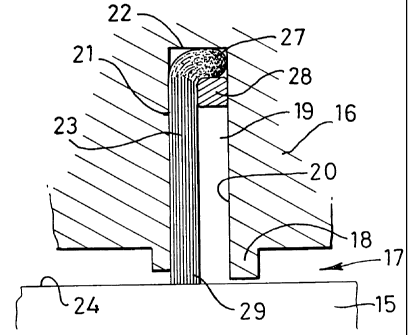
Referring initially to Figure 1, there is shown a part of a rotary machine
such as a gas turbine engine having a rotor shaft 15 mounted for rotation
within
a housing 16, the housing defining a bore 17 through which the shaft extends.
The bore is machined so that there is a leg 18 arranged closely to surround
the
shaft 15 and there is a slot 19 extending radially outwardly into the housing,
from the bore 17. The slot 19 is of simple rectangular cross-sectional shape
and has a high pressure side wall 20, an opposed low pressure side wall 21
and a base wall 22. The housing could be a separate carrier, releasably
attached to the main housing of the rotary machine.
A flexible brush seal element 23, shown also in Figure 2, is mounted in
the slot 19 in order to effect a seal between the housing 16 and the external
circumferential surface 24 of the shaft 15. The brush seal element 23
comprises a plurality of individual bristles 25 each made of metallic wire and
having their one ends 26 (that is, their radially outer ends) fused together
either
by a welding process or a brazing process, thereby forming a bead 27
CA 02394669 2002-06-17
WO 01/48404 PCT/GB00/04923
-7-
extending along the length of the element 23. Each bristle extends at a
common angle to the true radial direction, or to a tangent to the surface at
the
point of contact of the bristle tip with the surface, though the bristles
could, for
some applications, extend in the true radial direction or normally to said
tangent, as appropriate.
The brush seal element 23 is held in the slot 19, with the bead 27
bearing on end wall 22 of the slot 19 by means of an anchoring strip 28
pressed
into the slot 19, after insertion of the seal element. The anchoring strip 28
is
typically made of a malleable metal such as soft stainless steel or a soft
nickel
or cobalt ally, though for less demanding applications, soft iron, copper, a
bronze alloy or an aluminium alloy may be used. The strip is forced into the
slot
19 between the high pressure side wall 20 of the slot and the surfaces of the
bristles facing that slot by a special tool which deforms the strip securely
to hold
the element in the slot and to effect a seal between the element and the walls
of the slot.
Following the fusing together of the bristles forming the brush seal
element 23, the fused one ends 26 are machined or subjected to a grinding
operation, so as to impart to the fused end a predetermined profile and
thickness. Then, the bristles of the brush seal are clamped using the machined
or ground fused end as a reference surface, so that the free ends 29 of the
bristles may be finished to an exact length, to within very close tolerances,
from
the reference surface. This may be performed either with the brush seal
element held lineally, or curved into an arcuate shape, at the same radius or
curvature as that at which the seal will be employed.
The pressure applied to the anchoring strip 28 should be sufficiently high
to ensure plastic deformation of the anchoring strip, so as firmly to engage
the
bead 27 of the brush seal element with the end wall 22 and also to wedge that
strip between the high pressure side wall 20 and the bristles immediately
adjacent the bead 27. In this way, the brush seal element will be held
securely
in position for service as a seal. To facilitate the insertion of the
anchoring strip
28, the end of the high pressure side wall 20 adjacent the shaft 15 may be
bevelled slightly, thereby giving a lead for the anchoring strip.
CA 02394669 2002-06-17
WO 01/48404 PCT/GBOO/04923
-8-
In the event that the brush seal element 23 becomes worn or damaged
when in service, the element may easily be removed following removal of the
housing, by grasping the projecting free ends 29 of the bristles and pulling
the
entire seal element out of the slot 19, the anchoring strip 28 being drawn out
with the seal element, following which a new brush seal element may be
installed, together with a new anchoring strip 28.
Throughout the following description of modifications to the embodiment
described above and alternative embodiments, the same reference numbers
are used to denote the same, or substantially the same, components; insofar as
is appropriate, those components will not be described again.
In the modified form of seal assembly shown in Figure 3, a support plate
31 is fitted into the slot 19 simultaneously with the insertion of the brush
seal
element 23, so as to lie between the bristles on the high pressure side of the
seal element and the high pressure side wall 20 of the slot. Then, the
anchoring strip 28 is pressed into the slot 19, between the support plate 31
and
the high pressure side wall 20. In this way, the risk of damage to the
bristles on
the high pressure side of the seal element 23 during insertion of the
anchoring
strip 28 may be obviated. Moreover, the support plate 31 may serve to support
the bristles 25 against excessive flexing in the axial direction, should the
pressure on the normally low pressure side of the seal momentarily increase
above the pressure on the normally high pressure side of the seal.
In the embodiment of Figure 4, the slot 19 is modified so as to provide
an undercut 32 joining into the main part of the slot, at the radially
outermost
end of the slot. In this case, the brush seal element 23 is inserted so that
the
bead 27 locates in the undercut 32, by moving the brush seal element in the
axial direction once the seal has fully been inserted in the slot 19. Then,
the
seal is held in position by inserting the anchoring strip 28 between the
bristles
on the high pressure side of the seal and the high pressure wall 20. In this
embodiment, the anchoring strip need be deformed only to a relatively small
extent in order to hold the brush seal element in position.
Figure 5 shows a modified form of the assembly of Figure 4. Here, a
support plate 33 is provided between the high pressure side of the bristles
and
CA 02394669 2002-06-17
WO 01/48404 PCT/GBOO/04923
-9-
the high pressure side wall 20 of the slot, in essentially the same manner as
has been described above in relation to Figure 3. The support plate 33 fulfils
the same functions as described for the support plate 31.
Figure 6 illustrates an alternative brush seal element design. Here, a
filler wire 35 is provided along the edge of the seal element intended for
location deepest into the slot 19, each bristle being of a sufficient length
to be
wrapped partially round the filler wire. Two constructions are possible;
either
each bristle extends just from the end of the seal element intended to effect
a
seal against some other component to the filler wire, but is partially wrapped
round the filler wire, or each bristle could be of a sufficient length to
extend from
the end of the seal element intended to effect a seal against some other
component up to and around the filler wire and back to lie adjacent the first
end
of the bristle. This second construction is shown in Figure 6. Following
wrapping of the bristles in this way, the bristles are fused together and to
the
filler wire, whereafter the brush seal element is finished in the same manner
as
has been described above conceming the shape and dimensions of the bead
27 and the length of the bristles extending therefrom.
Figure 7 illustrates the use of a brush seal assembly of substantially the
same configuration as that shown in Figure 4, but incorporated into a
labyrinth
seal. Here, the housing 37 in which the slot 19 is formed has a bore 38
profiled
with a plurality of annular ribs 39, each of substantially triangular cross-
sectional shape. Similarly, the shaft is machined to provide a labyrinth seal
portion 40, the circumferential surface of the shaft having ribs 41 which
interfit
with the ribs 40 of the housing. In this way, an elongated leakage path for
high
pressure gas is provided, so enhancing the sealing effect of the brush seal
element 23 fitted into the slot 19.
Figure 8 illustrates an alternative form of seal assembly. Here, a
housing (not shown) for a rotatable component 43 has a flange 44 extending
generally axially of the rotating component and having a cylindrical inner
surface 45. The rotatable component has a boss 46 formed at its free end, in
which boss there is a slot 47 of simple rectangular cross-sectional shape, and
opening through the surface of the boss facing cylindrical surface 45. A brush
CA 02394669 2002-06-17
WO 01/48404 PCT/GB00/04923
-10-
seal element 48 is installed in the slot 47 by an anchoring strip 49 in the
same
manner as has been described above with reference to Figure 1. The brush
seal element 48 here is of a slightly different form from that of element 23
used
in the embodiment of Figure 1, in that the bristles extend radially outwardly
from
the bead 50 so that the free ends 51 may engage the cylindrical surface 45. As
compared to the brush seal element 23, the packing density of the bristles
needs to be higher, so that when the brush seal element is curved as shown,
there is still a sufficient sealing effect between adjacent bristles despite
the
negative curvature of the seal element.
Figure 9 shows one way in which a sufficiently high packing density may
be achieved, for a seal element such as is used in the arrangement of Figure
8.
Here, the bristles are arranged in two layers 53 and 54, with the bristles in
each
layer extending at an angle to the true radial direction but the bristles in
each
layer extending at opposed angles to each other. Such a seal element may
conveniently be constructed by the technique as illustrated in Figure 6, but
by
bending the bristles as they pass round the bead wire 35, before the fusing
together of the bristles.
Figures 10 and 11 illustrate a brush seal assembly of this invention being
used to effect a seal between two planar surfaces 56 and 57 facing each other
and provided on respective components 59 and 60. The brush seal 61 is
arranged around an aperture 58 of an irregular shape, as best seen in Figure
11. The brush seal element is manufactured in the same manner as element
23 (Figure 1) or that of Figure 6, and is installed in slot 19 in component
59,
exactly as has been described above with reference to Figure 1. When
installed, the free ends 29 of the bristles project beyond surface 56 of
component 59 so as to engage surface 57 of component 60.
When completed, the seal of Figures 10 and 11 allows the components
to move relative to one another laterally, but not axially, whilst still
maintaining a
seal between the components.