Note: Descriptions are shown in the official language in which they were submitted.
CA 02395180 2002-06-11
WO 01/44790 PCT/US00/34113
s SEGMENTED ELECTRODE CAPILLARY DISCHARGE,
NON-THERMAL PLASMA APPARATUS AND PROCESS FOR PROMOTING
CHEMICAL REACTIONS
Cross-Reference to Related Apaalications
to This application claims the benefit of U.S. Provisional Application No.
60/171,198, filed December 15, 1999 and U.S. Provisional Application No.
60/171,324, filed December 21, 1999, are all hereby incorporated by reference
in
their entirety.
15 BACKGROUND OF THE INVENTION
Field of the Invention
The present invention is directed to system and method for generating plasma
discharge and, in particular, to a segmented electrode capillary discharge,
non-
thermal plasma process and apparatus.
Description of Related Art
A "plasma" is a partially ionized gas composed of ions, electrons, and neutral
species. This state of matter is produced by relatively high temperatures or
relatively
strong electric fields either constant (DC) or time varying (e.g., RF or
microwave)
2 s electromagnetic fields. Discharged plasma is produced when free electrons
are
energized by electric fields in a background of neutral atoms/molecules. These
electrons cause electron atom/molecule collisions which transfer energy to the
atoms/molecules and form a variety of species which may include photons,
metastables, atomic excited states, free radicals, molecular fragments,
monomers,
3 o electrons, and ions. The neutral gas becomes partially or fully ionized
and is able
to conduct currents. The plasma species are chemically active and/or can
physically
modify the surface of materials and may therefore serve to form new chemical
CA 02395180 2002-06-11
WO 01/44790 PCT/US00/34113
2
compounds and/or modify existing compounds. Discharge plasmas can also
produce useful amounts of optical radiation to be used for lighting. Many
other uses
for plasma discharge are available.
U.S. Patent Nos. 5,872,426; 6,005,349; and 6,147,452, each of which are
s herein incorporated by reference, describe a glow plasma discharge device
for
stabilizing glow plasma discharges by suppressing the transition from glow-to-
arc.
A dielectric plate having an upper surface and a lower surface and a plurality
of holes
extending therethrough is positioned over a cathode plate and held in place by
a
collar. Each hole in the dielectric acts as a separate active current limiting
micro-
1 o channel that prevents the overall current density from increasing above
the threshold
for the glow-to-arc transition. This conventional use of a cathode plate is
not efficient
in that it requires the input of a relatively high amount of energy. In
addition, the
reactor requires a carrier gas such as Helium or Argon to remain stable at
atmospheric pressure.
15 It is therefore desirable to develop a device that solves the
aforementioned
problem.
Summar)i of the Invention
The present invention consists of a system for generating non-thermal plasma
2 0 reactor system to facilitate chemical reactions. Chemical reactions are
promoted by making
use of the non-thermal plasma generated in a segmented electrode capillary
discharge non
thermal plasma reactor, which can operate under various pressure and
temperature regimes
including ambient pressure and temperature. The device uses a relatively large
volume,
high density, non-thermal plasma to promote chemical reaction upon whatever
fluid is
25 passed through the plasma (either passed through the capillary or passed
transverse
through the resulting plasma jet from the capillary. Examples of the
chemistry, which could
be performed using this method, include the destruction of pollutants in a
fluid stream, the
generation of ozone, the pretreatment of air for modifying or improving
combustion, the
destruction of various organic compounds, or as a source of light.
Additionally, chemistry
3 o can be performed on the surface of dielectric or conductive materials by
the dissociation and
oxidation of their molecules. In the case of pure hydrocarbons complete
molecular
CA 02395180 2002-06-11
WO 01/44790 PCT/US00/34113
3
conversion will result in the formation of carbon dioxide and water, which can
be released
directly to the atmosphere.
The reactor in accordance with the present invention is designed so that the
gaseous
stream containing chemical agents such as pollutants are exposed to the
relatively high
density plasma region where various processes such as oxidation, reduction,
ion induced
decomposition, or electron induced decomposition efficiently allow for
chemical reactions to
take place. The ability to vary the plasma characteristics allows for tailored
chemical
reactions to take place by using conditions that effectively initiates or
promotes the desired
chemical reaction and not heat up the bulk gases.
to In a preferred embodiment of the present invention the plasma reactor
includes a first dielectric having at least one capillary defined
therethrough, and a
segmented electrode including a plurality of electrode segments, each
electrode
segment is disposed proximate an associated capillary. Each electrode segment
may be formed in different shapes, for example, a pin, stud, washer, ring, or
disk.
The electrode segment may be hollow, solid, or made from a porous material.
The
reactor may include a second electrode and dielectric with the first and
second
dielectrics separated by a predetermined distance to form a channel
therebetween
into which the plasma exiting from the capillaries in the first dielectric is
discharged.
The fluid to be treated is passed through the channel and exposed to the
plasma
2 o discharge. If the electrode segment is hollow or made of a porous
material, then the
fluid to be treated may be fed into the capillaries in the first dielectric
and exposed
therein to the maximum plasma density. The fluid to be treated may be exposed
to
the plasma discharge both in the capillaries as well as in the channel between
the
two dielectrics. The plasma reactor is more energy efficient than conventional
2 s devices and does not require a carrier gas to remain stable at atmospheric
pressure.
The plasma reactor has a wide range of application, such as the destruction of
pollutants in a fluid, the generation of ozone, the pretreatment of air for
modifying or
improving combustion, and the destruction of various organic compounds, and
surface cleaning of objects.
3 o The present invention is directed to a plasma reactor including a first
dielectric
having at least one capillary defined therethrough, and a segmented electrode
CA 02395180 2002-06-11
WO 01/44790 PCT/US00/34113
4
including a plurality of electrode segments, each electrode segment disposed
proximate an associated capillary.
In addition, the present invention also provides a method of treating a fluid
in
a plasma reactor as described above. Initially, a fluid to be treated is
passed through
one or more electrode segments and associated capillaries. The fluid is able
to pass
through the electrode segment if the segment is hollow or made of a porous
material.
The fluid to be treated while being passed through the capillary is exposed to
the
plasma discharge prior to exiting from the capillary. In addition, or instead
of,
passing the fluid to be treated through the electrode segment, the fluid to be
treated
to may be passed through a channel defined between the first dielectric and a
second
dielectric. In the channel, the fluid to be treated is exposed to plasma
discharged
from the capillary. Accordingly, the fluid to be treated may be passed and
exposed
to the maximum plasma density in the capillaries defined in the first
dielectric as well
as in the plasma region (channel) between the two dielectrics.
Brief Description of the Drawing
The foregoing and other features of the present invention will be more
readily apparent from the following detailed description and drawings of
illustrative
embodiments of the invention wherein like reference numbers refer to similar
2 o elements throughout the several views and in which:
Figure 1 a is a cross-sectional longitudinal view of an exemplary single
annular
segmented electrode capillary discharge plasma reactor system in accordance
with
the present invention;
2 s Figure 1 b is a cross-sectional lateral view of the plasma reactor system
of
Figure 1 a along line B-B;
Figure 1c is an enlarged top view of a single electrode segment and
associated capillary in the plasma reactor system in Figure 1 a;
Figure 1 d is an enlarged cross-sectional view of the arrangement of a single
3 o electrode segment and associated capillary in the reactor system in Figure
1 a;
CA 02395180 2002-06-11
WO 01/44790 PCT/US00/34113
Figure 1 a is a cross-sectional longitudinal view of another embodiment of a
single annular segmented electrode capillary discharge plasma reactor system
in
accordance with the present invention with a hollow inner segmented electrode
having a substantially uniform thickness and varied capillary hole density in
the first
5 dielectric;
Figure 1f is a cross-sectional longitudinal view of yet another embodiment of
a single annular segmented electrode capillary discharge plasma reactor system
in
accordance with the present invention with a hollow inner segmented electrode
having a non-uniform thickness and substantially uniform capillary hole
density in the
to first dielectric;
Figure 2a is a cross-sectional longitudinal view of an exemplary embodiment
of a system having two annular segmented electrode capillary discharge plasma
reactors in accordance with the present invention;
Figure 2b is a cross-sectional lateral view of an exemplary embodiment of a
i5 system having eight annular segmented electrode capillary discharge plasma
reactors in accordance with the present invention;
Figure 3a is a cross-sectional longitudinal view of a single rectangular
shaped
segmented electrode capillary discharge plasma reactor system in accordance
with
the present invention;
2 o Figure 3b is a top view of the reactor of Figure 3a;
Figure 4 is a cross-sectional longitudinal view of an exemplary system having
multiple rectangular shaped segmented electrode capillary discharge plasma
reactors in accordance with the present invention;
Figure 5a is a cross-sectional view of an exemplary hollow pin electrode
25 segment partially inserted into an associated capillary defined in the
first dielectric;
Figure 5b is a top view of the electrode segment of Figure 5a;
Figure 6a is a cross-sectional view of an exemplary solid pin electrode
segment having a blunt tip partially inserted into an associated capillary
defined in
the first dielectric;
3 o Figure 6b is a top view of the electrode segment of Figure 6a;
CA 02395180 2002-06-11
WO 01/44790 PCT/US00/34113
6
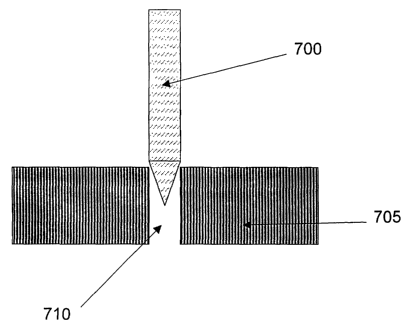
Figure 7a is a cross-sectional view of an exemplary solid pin electrode
segment having a pointed tip partially inserted into an associated capillary
defined
in the first dielectric;
Figure 7b is a top view of the electrode segment of Figure 7a;
s Figure 8a is a cross-sectional view of an exemplary solid substantially flat
electrode segment substantially flush with an associated capillary defined in
the first
dielectric;
Figure 8b is a top view of the electrode segment of Figure 8a;
Figure 8c is a cross-sectional view of an exemplary solid substantially flat
1 o electrode segment a portion of which extends into an associated capillary
defined in
the first dielectric;
Figure 8d is a top view of the electrode segment of Figure 8c;
Figure 8e is a cross-sectional view of an exemplary hollow substantially flat
electrode segment substantially flush with an associated capillary defined in
the first
15 dielectric;
Figure 8f is a top view of the electrode segment of Figure 8e;
Figure 9a is a cross-sectional view of an electrode segment associated with
one capillary of the first dielectric also having auxiliary channels defined
therein;
Figure 9b is a top view of the embodiment of Figure 9a;
2 o Figure 1 Oa is a cross-sectional view of an alternative embodiment of an
electrode segment associated with one capillary of a first dielectric having
auxiliary
channels in fluid communication with the capillary;
Figure 10b is a top view of the embodiment of Figure 10a;
Figure 11 is an exemplary surface cleaning system in accordance with the
25 present invention;
Figure 12a is a schematic diagram of an exemplary air handler with a
segmented electrode capillary discharge plasma reactor in accordance with the
present invention; and
Figure 12b is an enlarged view of the segmented electrode capillary discharge
3 o plasma reactor in Figure 12a.
CA 02395180 2002-06-11
WO 01/44790 PCT/US00/34113
7
Detailed Description of the Invention
The segmented electrode capillary discharge, non-thermal plasma reactor in
accordance with the present invention is designed so that a solid or a fluid
(e.g., a
liquid, vapor, gas, or any combination thereof) containing chemical agents,
for
s example, an atomic element or a compound, is exposed to a relatively high
density
plasma in which various processes, such as oxidation, reduction, ion induced
composition, and/or electron induced composition, efficiently allow for
chemical
reactions to take place. By way of example, the chemical agents may be
Volatile
Organic Compounds, Combustion Air or Combustion Exhaust Gases. The ability to
1 o vary the energy density allows for tailored chemical reactions to take
place by using
enough energy to effectively initiate or promote desired chemical reactions
without
heating up the bulk gas.
By way of example the present invention will be described with respect to the
application of using the plasma reactor to purify or treat a contaminated
fluid. It is,
15 however, within the intended scope of the invention to use the device and
method
for other applications.
Longitudinal and lateral cross-sectional views of an exemplary single annular
segmented electrode capillary discharge plasma reactor system in accordance
with
the present invention are shown in Figures 1 a and 1 b, respectively. The
single
2 o annular segmented electrode capillary discharge plasma reactor 100 in
Figure 1 a
includes an inlet 150 for receiving the fluid to be treated. A flow transition
conduit
110 is disposed between the inlet 150 and a reaction chamber 155 to streamline
the
flow of fluid to be treated. That is, the flow transition conduit 110
distributes the fluid
to be treated substantially uniformly priorto its introduction into the
reaction chamber
25 155. Reaction chamber 155 includes a first dielectric 115 and a second
electrode
120. The second electrode 120 is disposed circumferentially about at least a
portion
of the outer surface of a second dielectric 115 and extends in a longitudinal
direction
along at least a portion of the length of the reaction chamber 155. In a
preferred
embodiment, the second electrode 120 is insulated and composed of a metallic
or
3o non-metallic conductor. Throughout the
descriptionoftheinventionanyconventional
material may be used as a dielectric such glass or ceramic.
CA 02395180 2002-06-11
WO 01/44790 PCT/US00/34113
8
Disposed inside the reaction chamber 155 is a hollow tube 147 perforated
with holes. A first dielectric 135 having capillaries 146 defined therein is
disposed
about the hollow tube 147. The first and second dielectrics may be the same or
different materials. Interposed between the hollow tube 147 and first
dielectric 135
s is a segmented electrode 140 comprising a plurality of electrode segments. A
power
supply 130 is connected to the second electrode 120 and the segmented
electrode
140.
Although shown in Figure 1 a as a plate, the second electrode 120 may
alternatively
be a segmented electrode comprising a plurality of electrode segments.
1 o Alternatively, the second electrode 120 and second dielectric 115 may be
eliminated
altogether.
In the embodiment shown in Figure 1 a, each electrode segment 140
is in the shape of a ring or washer having a hole 146 defined therethrough.
Enlarged
top and cross-sectional views of a single electrode segment 140 in the shape
of a
15 hollow ring are shown in Figures 1 c and 1 d, respectively. The hollow ring
shaped
electrode segment 140 is disposed in contact with the first dielectric 135. In
an
alternative embodiment, electrode segment 140 may be disposed above and
separated from the first dielectric 135 by a predetermined distance, or extend
any
desired depth into the capillary 148. The electrode segment 140 is arranged so
that
2 o the holes in the hollow tube 147, the holes 146 in the electrode segments
140, and
the capillaries 148 defined in the first dielectric 135 are substantially
aligned with one
another. Holes in the hollow tube 147 and electrode segment 140 provide a
conduit
through which the fluid to be treated may be passed and exposed to the maximum
plasma density in the capillaries 148 defined in the first dielectric 135 as
well as in
2 s the plasma region between the two dielectrics 115, 135. It is within the
scope of the
invention to eliminate the hollow tube 147altogether and merely expose or
treat the
contaminated fluid in the plasma region between the two dielectrics.
Plasma is generated in a channel 125 between the dielectrics 115, 135 and
in the capillaries 148 defined in the first dielectric 135. The capillaries
148 defined
3 o in the second dielectric 135 can vary in diameter, preferably from a few
microns to
a few millimeters, and can also vary in density or spacing relative to one
another.
CA 02395180 2002-06-11
WO 01/44790 PCT/US00/34113
9
The density or spacing of the capillaries 148 may be varied, as desired, so as
to
generate a plasma discharge over a portion or the entire length of the
reaction
chamber 155. In addition, the diameter of the capillaries 148 may be selected
so as
to obtain a desired capillary plasma action.
In operation, fluid to be treated is received at the inlet 150 and passed
through the transition conduit 110 into the channel 125 of the reaction
chamber 155.
If the electrode segments 140 are hollow, as shown in Figure 1 d, then the
fluid to be
treated may also be passed through the electrode segments 140 and into the
capillaries 148. A capillary plasma discharge is created in the capillaries
148 and the
to channel 125 upon the application of a voltage from the power supply 130.
The
plasma discharge produces chemical reactions that destroy the contaminants in
the
fluid to be treated. Accordingly, treatment of the contaminated fluid by
exposure to
the plasma may occur in the capillaries 148 and/or the channel 125. The plasma
generated in the capillaries and channel promotes chemical reactions that
facilitate
processes such as the destruction of contaminants.
Figures 1e and 1f show exemplary alternative embodiments of a single
annular segmented electrode capillary discharge plasma reactor in accordance
with
the present invention. Unlike the embodiment shown in Figure 1 a in which the
reactor chamber 155 includes a hollow tube, in Figures 1 a and 1 f, the hollow
tube
147 may be eliminated as a result of using a U-shaped inner electrode 165. In
both
embodiments, the fluid to be treated is exposed to the maximum plasma density
in
the capillaries 195 defined in the first dielectric 170 as well as in the
plasma region
between the two dielectrics 170, 175. The reaction chamber in Figures 1e and
1f
has an inlet 160 directly connected to a plurality of electrode segments that
together
2 s form a hollow inner segmented electrode 165 in contact with a first
dielectric 170.
Capillaries 195 are defined in the first dielectric 170 along its length in a
longitudinal
direction. Opposite its open end the first dielectric 170 has a closed end
185,
proximate an outlet 190, to prevent the fluid to be treated from escaping from
the
reaction chamber without being subject to chemical reactions when exposed to
the
3 o plasma.
Despite their overall similar configuration, the embodiments shown in Figures
CA 02395180 2002-06-11
WO 01/44790 PCT/US00/34113
1 a and 1 f differ with respect to the first dielectric and inner segmented
electrode. In
Figure 1e, inner segmented electrode 165 has a substantially uniform cross-
section
(thickness) and variable capillary hole density (spacing) defined in the first
dielectric
170 along the longitudinal length of the reaction chamber 155. While, in
Figure 1f,
s the inner segmented electrode 165 has a non-uniform cross-section
(thickness) and
substantially uniform capillary density (spacing) defined in the first
dielectric along the
longitudinal length ofthe reaction chamber 155. The cross-sectional thickness
ofthe
inner segmented electrode 165, the density (spacing) of the capillaries 195
defined
in the first dielectric 170, and/or the diameter of the capillaries 195 in the
first
1 o dielectric 170 may be varied along the longitudinal length of the reaction
chamber to
achieve substantially uniform flow therein.
In operation, the fluid to be treated enters the inlet 160 and passes into the
hollow inner U-shaped segmented electrode 165. Once within the hollow portion
of
the inner segmented electrode 165, the fluid to be treated is received in the
holes
146 defined in the electrode segments that comprise the inner electrode and
passed
out through the capillaries 195 defined in the first dielectric 170.
Multiple annular reactors may be combined in a single system. By way of
example, Figure 2a is a longitudinal cross-sectional view of a system having
two
annular reactors, while Figure 2b shows a lateral cross-sectional view of a
system
2 o having eight reactors 210 enclosed in a common housing 205. The space in
the
housing 205 between the reactors 210 is filled with a dielectric material 215
to
ensure that all of the fluid to be treated passes through the plasma region
155 of a
reactor 210. The system may be designed to include any number of reactors to
be
arranged as desired within the housing. This embodiment is particularly suited
for
2s the treatment of relatively large flow rates of fluid to be treated wherein
a relatively
large reactor system is desirable. By way of example, each reaction chamber
shown
in Figures 2a and 2b may be configured similar to that shown and described
with
respect to Figure 1 a-1f.
Instead of the reactor having an annular or tubular shape as shown and
3 o described in the embodiments thus far, the reactor may have a rectangular
shape
as shown in Figures 3a and 3b. The dimensions, e.g., the length, width and gap
CA 02395180 2002-06-11
WO 01/44790 PCT/US00/34113
11
length, of the reactor 300 may be modified, as desired, to accommodate
specific
applications. Reactor 300 has an inlet 350 connected to the reaction chamber
by a
transition conduit 310, as in the foregoing embodiments. The reaction chamber
itself
includes a second conductive electrode 340, preferably extending substantially
the
s full width and length of the reaction chamber. Conductive electrode 340 is
embedded in a second dielectric plate 315. A first dielectric plate 330 having
holes
or perforations therein that form capillaries is in direct contact with an
inner
segmented electrode 325 comprising a plurality of electrode segments. By way
of
example, each electrode segment is a hollow shaped ring or washer, as shown in
1 o Figures 1 c and 1 d. A hollow tube 335 is connected to the segmented
electrode 325
that may be used as a conduit through which a supply of gases may be fed to
improve the stability or optimize chemical reactions in the plasma. Chemical
reactions take place in a plasma region that includes the capillaries defined
in the
first dielectric 330 as well as the area between the two dielectrics 315, 320.
The
15 treated fluid is discharged from the transition conduit 310' and through
the outlet 305.
The outside housing 360 of the reactor 300 is preferably made of a dielectric
material.
Multiple rectangular plate reactors such as the one shown in Figures 3a and
3b may be combined in a single reactor. Figure 4, for example, shows a system
400
2 o having four rectangular plate reactors 410 placed substantially parallel
with respect
to each other and encased in a common housing 415. The space within the
housing
415 between the reactors 410 is filled with a dielectric material to ensure
that all of
the fluid to be treated is channeled through the plasma region of one of the
reactors.
This embodiment is particularly well suited for applications in which a
relatively large
2 5 flow rate of contaminated gas is to be treated and a relatively large
combined reactor
system is desirable.
In the embodiments shown in Figures 1-4, the dimensions of the reaction
chamber may be selected as desired such that the residence time of the
contaminants within the plasma regions is sufficient to ensure destruction of
the
3 o contaminant to the desired level, for example, destruction down to the
contaminants
down to the molecular level.
CA 02395180 2002-06-11
WO 01/44790 PCT/US00/34113
12
Below are four exemplary reaction mechanisms that play an important role in
plasma enhanced chemistry. Common to all mechanisms are electron impact
dissociation and ionization to form reactive radicals. The four reaction
mechanisms
are summarized in the examples below:
(1 ) oxidation: e.g. conversion of CH4 to CO2 and HZO
e_ + Oz ~ e_ + O(3P) + O(1 D)
O(3P) + CH4 ~ CH3 + OH
CH3 + OH ~ CHZ + H20
CHZ + 02 ~ Hz0 + CO
CO+O~COZ
(2) reduction: e.g. reduction of NO into N2 + O
e_+N2 ~ e_+N+N
N+NO ~ N2+O
(3) electron induced decomposition: e.g. dissociative electron attachment to
CC14
e- + CC14 ~ CC13 + CI-
CC13+OH~CO+CIz+HCI
(4) ion induced decomposition: e.g. decomposition of methanol
e- + NZ ~ 2e- + NZ+
NZ+ + CH30H ~ CH3+ + OH + NZ
2 0 CH3+ + OH ~ CHZ+ + H20
CHz+ + 02 ~ H20 + CO'
By way of example, in the foregoing embodiments the electrode segments
comprising the segmented electrode have been shown and described as a hollow
2 s shaped ring or washer. However, the electrode segments may be configured
in
many different ways. Figures 5-8 show the configuration of a single electrode
segment and an associated capillary in the first dielectric. Although only a
single
capillary and associated electrode segment is shown, the same electrode
segment
structure and arrangement may be used for a plasma reactor having multiple
3 o capillaries. Figure 5a is a cross-sectional view of a first embodiment of
a hollow pin
or cylinder shaped electrode segment 520 inserted partially into a respective
capillary
510 defined in a first dielectric 505. In an alternative embodiment, the
electrode
CA 02395180 2002-06-11
WO 01/44790 PCT/US00/34113
13
segment 520 may be disposed above, substantially flush with the dielectric, or
extend any desired depth into the capillary 510. Since the electrode segment
is
hollow the fluid to be treated may be passed through the electrode segment and
into
the capillaries of the first dielectric and/orthrough a channel defined
between the two
s dielectrics. Accordingly, treatment of the fluid by exposure to the plasma
may occur
in the capillaries and/or the channel.
Figures 6a and 6b show a cross-sectional view and a top view, respectively,
of a solid segmented electrode 610 in the shape of a pin inserted partially
into a
capillary 600 defined in a first dielectric 605. In an alternative embodiment,
the
1 o electrode segment 610 may be disposed above, substantially flush with, or
inserted
to any desired depth into the capillary 600. The electrode segment 610 may be
solid
or porous. If a porous electrode 610 is used, the fluid to be treated may be
passed
directly through the electrode segment thereby optimizing its exposure to the
plasma
discharge that occurs within the capillary. Since the fluid to be treated when
passed
15 through the electrode segment may be treated by the plasma discharge
created in
the capillary 600 itself, in this case, the second electrode and second
dielectric may
be eliminated altogether. Another advantage to using a porous electrode 610 is
that
it also serves as a conduit for the supply of gas to improve the stability,
optimize the
chemical reactions with the plasma, or perform chemical reactions within the
plasma.
2o In Figures 6a and 6b the electrode segment has a blunt end, e.g.,
substantially flat , round, concave, or convex, whereas in an alternative
embodiment
shown in Figure 7a and 7b the electrode segment 700 terminates in a pointed
tip.
The exemplary electrode segment shown in both embodiments has a cylindrical
shape, however, any desired shape may be used. Similarly, the shape and/or
2 s dimensions of the capillary 600, 710 need not correspond to that of the
electrode
segment 610, 700, respectively, but instead can be any shape, length, or angle
of
direction through the dielectric. Figures 6b and 7b are top views of the
electrode
segment and dielectric of Figures 6a, 7a, respectively. It is clear from the
top views
in Figures 6b, 7b that the diameter of the electrode segment 610, 700 is
substantially
3 o equal to the diameter of the capillary 600, 710. The electrode segment and
its
respective capillary, however, need not be substantially equal in diameter. In
addition, the thickness of the first dielectric need not be substantially
uniform and can
vary over the length of the reactor. The capillaries are used to sustain
capillary
plasma discharge and may also be used to introduce into the plasma region
gases
CA 02395180 2002-06-11
WO 01/44790 PCT/US00/34113
14
to stabilize the discharge, or deliver reactants to the origin of the plasma
for the
purpose of performing chemistry.
Figures 8a-8e show yet another embodiment of the configuration of the
segmented electrode wherein each electrode is substantially flat, e.g., a
washer, ring
s or disk. In particular, Figures 8a and 8b show a cross-sectional view and a
top view,
respectively, of a solid substantially flat electrode segment 800 in the shape
of a disk
that is disposed over the capillary 810 so as to be substantially flush and in
contact
with the first dielectric 805. Alternatively, as shown in Figures 8c and 8d,
the solid
substantially flat electrode segment may extend partially into the capillary
810. It is
to also within the intended scope of the invention to use a substantially flat
electrode
segment 820 having a hole 811 defined therein to form a ring or washer, as
shown
in Figures 8e and 8f.
Different configurations forthe electrode segment and its associated capillary
may be used based on the following conditions: i) whether the electrode
segment is
is solid, hollow, or porous; ii) the outer and/or inner shape of the electrode
segment; iii)
the dimensions of the electrode segment; and iv) whether the electrode segment
is
disposed above, substantially flush with the dielectric, or inserted at a
predetermined
depth into the capillary.
The portion of the reaction chamber shown in Figure 1 d includes a second
2 o dielectric 115, whereas the second dielectric has been omitted in the
embodiments
shown in Figures 5a, 5b, 6a, 6b, 7a, 7b, 8a-8f. Any of these configurations in
which
the segmented electrode is hollow or made of a porous material may be
implemented with or without a second dielectric and second electrode.
It is also within the intended scope of the invention to define auxiliary
channels
2s of any shape, dimension, or angle of direction in the first dielectric that
do not have
an associated electrode segment. Figure 9a and 9b show a cross-sectional view
and
a top view, respectively, of an exemplary solid annular (pin) electrode having
a
pointed tip that is partially inserted into a capillary 910. Auxiliary
channels 915 are
defined in the dielectric 905 substantially parallel to the capillary 910 into
which the
3 o electrode segment 900 has been inserted. Fluids may be introduced into the
auxiliary channels 915 to stabilize the plasma discharge or deliver reactants
to the
plasma for improving the chemical reactions. The auxiliary channels 915 may be
defined in the dielectric at any desired angle. Figures 10a and 10b show two
auxiliary channels 1015 defined in the dielectric 1005 so as to be in fluid
CA 02395180 2002-06-11
WO 01/44790 PCT/US00/34113
communication with the capillary 1010.
Each of the aforementioned segmented electrode configurations have been
shown and described by way of example. The features of each embodiment may
be modified or combined with those of other embodiments as desired. The
invention
s is not to be limited to the particular shape, dimension, number, or
orientation of the
electrodes or capillaries shown by way of example in the figures.
The aforementioned embodiments have been described with reference to the
treatment or purification of a contaminated fluid. Another application for the
use of
the plasma reactor in accordance with the present invention is for treating or
cleaning
1 o a solid or porous surface. Figure 11 is a schematic diagram of an
exemplary
surface cleaning system in accordance with the present invention. System 1100
includes a reactor 1125 including a perforated dielectric plate and a
segmented
electrode together represented as 1105. The segmented electrode and dielectric
plate may be configured in accordance with any of the embodiments described
15 above. Plasma is generated in the capillaries and discharged therefrom in
the form
of plasma jets 1110. An object is positioned so that the surface of the object
to be
cleaned is exposed to the plasma jets 1110. In the embodiment shown in Figure
11,
the object 1115 to be cleaned is positioned between two dielectrics 1105,
1120.
Alternatively, the second dielectric 1120 may be eliminated, as described
above.
2 o In yet another application, the segmented electrode capillary discharge
plasma system may be used to purify gases. Figure 12a is a schematic diagram
of
an exemplary air handler with a segmented electrode capillary discharge plasma
device for cleaning contaminated gases. The airto be purified is received in
the inlet
1200, mixes with air from a return inlet 1210, and then passes through a
segmented
2s electrode capillary discharge plasma air cleaning device 1220 before
exiting the
system. Figure 12b is an enlarged view of an exemplary segmented electrode
capillary discharge plasma air cleaning device 1220 that includes a plurality
of
segmented electrodes and opposing perforated dielectric plates arranged
substantially parallel to one another. Plasma regions are formed between the
3 o segmented electrode and opposing dielectric plates. In the exemplary
embodiment
shown in Figure 12a the segmented electrode capillary discharge plasma air
cleaning device 1220 is arranged after the supply air and mixing air are
combined.
The reactor system could alternatively be designed so that the segmented
electrode
capillary discharge plasma air cleaning device 1220 is arranged at any one
location
CA 02395180 2002-06-11
WO 01/44790 PCT/US00/34113
16
or at multiple locations within the system.
The segmented electrode capillary discharge, non-thermal plasma reactors
in accordance with the present invention can be used to perform a variety of
chemical reactions by exposing a fluid or surface containing the desired
reactants
s to the high density plasma region where various processes such as oxidation,
reduction, ion induced decomposition, or electron induced decomposition
efficiently
allow for chemical reactions to take place. The fluid to be treated may be fed
either
through the channel between the two dielectrics (transversely to the flow of
the
plasma discharged from the capillaries of the dielectric) and/orthrough the
capillaries
1 o themselves (the point of origin of the plasma). Examples of reactions
include:
chemistry on various organic compounds such as Volatile Organic Compounds
(VOCs) either single compounds or mixtures thereof; semi-volatile organic
compounds, Oxides of Nitrogen (NOx), Oxides of Sulfur (SOx), high toxic
organics,
and any other organic compound that can be in the form of vapors of aerosols.
In
15 addition, the reactor can be used to pretreat combustion air to inhibit
formation of
Nox and increase fuel efficiency. Additional uses of the plasma includes the
generation of ozone and ultraviolet light, and treatment of contaminated
surfaces.
Thus, while there have been shown, described, and pointed out fundamental
novel features of the invention as applied to a preferred embodiment thereof,
it will
2 o be understood that various omissions, substitutions, and changes in the
form and
details of the devices illustrated, and in their operation, may be made by
those skilled
in the art without departing from the spirit and scope of the invention. For
example,
it is expressly intended that all combinations of those elements and/or steps
which
perform substantially the same function, in substantially the same way, to
achieve
25 the same results are within the scope of the invention. Substitutions of
elements
from one described embodiment to another are also fully intended and
contemplated. It is also to be understood that the drawings are not
necessarily
drawn to scale, but that they are merely conceptual in nature. It is the
intention,
therefore, to be limited only as indicated by the scope of the claims appended
3 o hereto.