Note: Descriptions are shown in the official language in which they were submitted.
CA 02395235 2002-07-03
WO 01/49186 PCT/USO1/00286
-1-
APPARATUS FOR CLOSING TISSUE PUNCTURES
Field Of The Invention
The present invention relates to apparatus and methods for closing and/or
sealing
punctures or other openings in a vessel wall or other body lumen generally
formed in
conjunction with a diagnostic or therapeutic procedure, and more particularly
to introducer
sheaths including puncture site closure elements and methods of their use.
Background Of The Invention
Catheterization and interventional procedures, such as angioplasty and
stenting, are
generally performed by inserting a hollow needle through a patient's skin and
muscle
tissue into the vascular system. A guide wire is then passed through the
needle lumen into
the patient's blood vessel. The needle is removed and an introducer sheath is
advanced
over the guide wire into the vessel. A catheter is typically passed through
the lumen of the
introducer sheath and advanced over the guide wire into position for a medical
procedure.
The introducer sheath therefore facilitates insertion of various devices into
the vessel while
minimizing trauma to the vessel wall and minimizing blood loss during a
procedure.
Upon completion of the medical procedure, the catheter and introducer sheath
are
removed, leaving a puncture site in the vessel. Commonly, external pressure is
applied
until clotting and wound sealing occurs. This procedure, however, is time
consuming and
expensive, requiring as much as an hour of a physician's or nurse's time. It
is also
uncomfortable for the patient, and requires that the patient be immobilized in
an operating
room, catheter lab, or holding area. Furthermore, a risk of hematoma exists
from bleeding
prior to hemostasis.
Various apparatus have been developed for percutaneously sealing a vascular
puncture by occluding or suturing the puncture site. For example, U.S. Patent
Nos.
5,192,302 and 5,222,974 to Kensey et al., describe the use of a biodegradable
plug
delivered through the introducer sheath into the puncture site. When deployed,
the plug
seals the vessel and provides hemostasis. Such devices have been slow to gain
acceptance
in the medical community, however, due to difficulties encountered in
positioning the plug
within the vessel. Moreover, the agents used to occlude the puncture site are
animal
CA 02395235 2002-07-03
WO 01/49186 PCT/USO1/00286
-2-
derived, typically collagen-based. Thus, a risk of adverse immunoresponse
exists with
their use.
Another previously known technique includes percutaneously suturing the
puncture site with specialized apparatus. Such apparatus are described, for
example, in
U.S. Patent No. 5,304,184 to Hathaway et al. While percutaneous suturing
devices may be
effective, a significant degree of skill may be required on the part of the
practitioner. Also,
because such devices are mechanically complex, they tend to be relatively
expensive to
manufacture.
Surgical staples and resilient clips for external skin wound closure are well
known
in the art. Examples include U.S. Patent No. 5,026,390 to Brown and U.S.
Patent No.
5,683,405 to Yacoubian et al., which both describe resiliently deformable
closure devices
suitable for manual external application.
To reduce the cost and complexity of percutaneous puncture closure devices,
such
devices employing resilient clips or staples have been developed. U.5. Patent
No.
5,478,354 to Tovey et al. describes the use of resilient clips in conjunction
with a trocar to
close abdominal puncture wounds. U.5. Patent No. 5,810,846 to Virnich et al.
describes a
specialized apparatus for closing a vascular puncture site with a plastically
deformable
clip. The apparatus preferably is advanced over a guide wire through a cannula
to the
surface of the puncture site, where the staple-like clips are delivered to
close the wound.
U.S. Patent No. 5,782,861 to Cragg et al. describes specialized apparatus for
closing a puncture site with a detachable clip. The apparatus includes a
hollow shaft,
having a distal end formed with one or more opposed pairs of resilient
grasping prongs,
that is advanced over a guide wire through a coaxial hollow tube to a position
at the distal
end of the tube just proximal of the puncture.
The grasping prongs are extended beyond the distal end of the tube to grasp
the
vessel on opposing sides of the puncture. The shaft is then partially
retracted, causing the
prongs to contract within the tube, thereby sealing the puncture site. Both of
the devices
described in the foregoing patents have the drawback that a separate device
must be
deployed through the introducer sheath to close the puncture site, thus
prolonging the
procedure. Moreover, both devices require relatively complex apparatus and
involve time
consuming manipulation to achieve hemostasis.
CA 02395235 2002-07-03
WO 01/49186 PCT/USO1/00286
-3-
The use of backbleed indication as a positioning technique within a vascular
puncture is also known. For example, U.S. Patent No. 4,317,445 to Robinson
describes a
flashback chamber for providing visual indication of venous entry of a
cannula. This
device, however, does not discuss vascular wound closure. U.S. Patent No.
5,676,689 to
Kensey et al., which claims priority from the 5,222,974 patent discussed
above, uses a
vessel location device to simplify positioning of the biodegradable plug. The
vessel
locator enables blood from the vessel to flow there through so that the
position of the
vessel may be determined. The Kensey et al. system, however, only proffers one
closure
device, and that device is complex and raises concerns about biocompatibility.
It also
requires the closure component to be positioned within the puncture, thereby
increasing
the likelihood of dangerous over-advancement of the plug into the vessel.
In view of the foregoing, it would be desirable to provide apparatus and
methods
suitable for vascular puncture closure that overcome disadvantages of
previously known
devices.
Summary of the Invention
. The present invention is directed to apparatus and methods for closing
and/or
sealing punctures or other openings in a vessel wall or other body lumen such
as those
formed during percutaneous or other diagnostic or therapeutic procedures.
In accordance with one aspect of the present invention, an apparatus is
provided
that includes an introducer sheath having an integrated wound closure
component. The
closure component includes a resilient spring clip disposed on and advanceable
over the
exterior of the introducer sheath in an expanded delivery configuration until
opposite sides
of the clip pierce a vessel on opposite sides of a puncture site. The
introducer sheath is
then withdrawn, enabling the spring clip to contract to its unstressed
deployed
configuration, thereby drawing opposite sides of the puncture together and
closing the
wound. Indicators may also be provided for confirming when the spring clip has
engaged
the vessel wall, thereby indicating to the surgeon that the clip has been
deployed and the
introducer sheath may be withdrawn.
In accordance with another aspect of the present invention, a closure
component is
provided that includes a bioabsorbable and deformable clip with a
bioabsorbable fastener.
The closure component is disposed on and advanceable over the exterior of an
introducer
CA 02395235 2002-07-03
WO 01/49186 PCT/USO1/00286
-4-
sheath in an expanded delivery configuration until opposite sides of the clip
pierce a vessel
on opposite sides of a puncture site. The clip may then be mechanically
deformed with the
fastener into a deployed configuration, thereby drawing opposite sides of the
puncture
together and closing the wound. Indicators may also be provided for confirming
when the
bioabsorbable clip has engaged the vessel wall to indicate to the surgeon that
the clip may
be deployed and the introducer sheath may be withdrawn.
In a preferred embodiment, the bioabsorbable clip resembles an inverted "Y"
with
pointed ends that puncture the vessel to be closed. The fastener includes a
bioabsorbable
locking collar that may be advanced down the length of the clip to bring the
pointed ends
together. In a second embodiment, the bioabsorbable clip includes a hoop with
pointed
legs extending therefrom. The hoop has two points of reduced thickness spaced
180
degrees apart on the circumference of the hoop. The fastener includes a
bioabsorbable
conical wedge that is pushed down into the hoop to force opposing sides of the
hoop
towards one another and bring the pointed legs together.
In accordance with yet another aspect of the present invention, an integrated
vascular device is provided that includes a sheath having a puncture closure
component
and puncture sealant. The closure component is disposed on and advanceable
over the
exterior of the sheath, which may, for example, include an introducer sheath,
a trocar, or a
catheter. The closure component may include any of a variety of apparatus
suited to close
a vascular puncture. Once the closure component has been actuated to close the
puncture,
sealant may be introduced to the exterior surface of the closed puncture,
preferably
through the sheath's interior lumen, where the sealant seals the puncture
closed. The
sheath with closure component may then be removed from the patient.
In a preferred embodiment, the closure component includes a twist closure
device.
The device pierces tissue surrounding the vascular puncture and then is
rotated to close the
wound. In an alternative embodiment, the closure component includes needles
and an
elastic segment surrounding the needles. The needles pierce the puncture with
the elastic
segment expanded. The segment is then allowed to resiliently contract to an
unstressed
configuration of smaller diameter, thereby drawing the needles together and
closing the
wound.
In an alternative embodiment, the needles, or prongs may be elastically
deformed
to an expanded diameter, in which they pierce the tissue adjacent to puncture.
The needles
CA 02395235 2002-07-03
WO 01/49186 PCT/USO1/00286
-5-
may then be allowed to resiliently contract to an unstressed configuration of
smaller
diameter, thereby closing the wound.
Sealant then may be introduced, preferably through the interior lumen of the
sheath
to seal the puncture closed. The sealant may include any of a variety of known
sealants,
including adhesives, sutures, and clips, all of which are preferably
bioabsorbable.
Alternatively, the closure component may include a sealant, and the closure
component
may be left in place within the vessel until hemostasis naturally occurs. In a
further
alternative, the closure component may include a monopolar electrode or
opposed bipolar
electrodes that cauterize the wound with RF current. In addition to
cauterization, RF
energy generates heat that beneficially causes shrinkage of the vascular
tissue, thereby
assisting closure of the wound. Thermal energy from electrical induction,
infrared light,
ultrasonic vibration, microwave or laser irradiation, and other means may also
be used to
seal the puncture.
Advantageously, the wound closure components of the present invention may be
inexpensively integrated into a standard-size introducer sheath, thereby
eliminating the
need for a separate closure device at the conclusion of a catheterization
procedure. The
present invention provides quick, safe, effective, and easy-to-use apparatus
for achieving
vascular closure that may overcome drawbacks of previously known devices.
Brief Description of the Drawings
The above and other objects and advantages of the present invention will be
apparent upon consideration of the following detailed description, taken in
conjunction
with the accompanying drawings, in which like reference characters refer to
like parts
throughout, and in which:
FIG. 1 is a side view of a vascular device constructed in accordance with the
present invention.
FIG. 2 is a cross sectional view of the closure component of the vascular
device of
FIG. 1.
FIGS. 3A-3D are side views of the resilient clip of the present invention
shown
from different angles in an expanded delivery configuration and in an
unstressed deployed
configuration.
CA 02395235 2002-07-03
WO 01/49186 PCT/USO1/00286
-6-
FIGS. 4A and 4B are isometric views of an alternative embodiment of the
resilient
surgical clip, constructed in accordance with the present invention and shown,
respectively, in an unstressed deployed configuration and in an expanded
delivery
configuration.
FIGS. SA-SF are side-sectional views of a vascular puncture site, illustrating
a
method of sealing the puncture site with the integrated vascular device of
FIG. 1.
FIG. 6 is a side view of another integrated vascular device constructed in
accordance with the present invention.
FIGS. 7A-7C are, respectively, a cross-sectional view of a closure component
of
the vascular device of FIG. 6, an exploded side view of proximal slots of the
closure
component, and an exploded side view of distal slots.
FIGS. 8A-8C are, respectively, views of a bioabsorbable clip and fastener of
the
present invention shown in top view in a delivery configuration, in side view
in the
delivery configuration, and in side view in a deployed configuration.
FIGS. 9A and 9B are isometric views of an alternative embodiment of the
bioabsorbable surgical clip and fastener, constructed in accordance with the
present
invention and shown, respectively, in a delivery configuration and in a
deployed
configuration.
FIGS. 10A-1 OB through 13A-13B are side-sectional views of the closure
component of FIG. 7A in use at a vascular puncture site, with corresponding
side views of
the proximal and distal slots of FIGS. 7B and 7C, illustrating a method of
sealing the
puncture site with the present invention.
FIG. 14 is a side view of a preferred embodiment of an integrated vascular
device
constructed in accordance with the present invention.
FIG. 15 is a side-sectional view of a sealing device for use with the vascular
device
of FIG. 14.
FIGS. 16A-16D are side views of the closure component of FIG. 14 in use at a
vascular puncture site, shown in section, with the sealing device of FIG. 2,
illustrating a
method of sealing the puncture site.
FIGS. 17A-17D are top views of the vascular puncture site of FIGS. 16A-16D,
corresponding to the side-sectional views of FIGS. 16A-16D, further
illustrating the
method of FIGS. 16A-16D.
CA 02395235 2002-07-03
WO 01/49186 PCT/USO1/00286
FIGS. 18A-18C are side-sectional views of an alternative embodiment of an
integrated vascular device of the present invention in use at a vascular
puncture site,
illustrating a method of sealing the puncture site.
FIGS. 19A-19E are side-sectional views of a further alternative embodiment in
use
at a vascular puncture site, illustrating a method of sealing the puncture
site.
FIGS. 20A and 20B are isometric views of a section of vessel including and
corresponding to the vascular puncture site of FIGS. 19A-19E, further
illustrating the
method of FIGS. 19A-19E.
Detailed Descr'intion Of The Invention
Referring to FIG. 1, a vascular device 10 is provided that includes an
introducer
sheath 12 coupled to a hub 14, a clip housing 16, and a clip actuator 18. The
introducer
sheath 12 includes a material typically used for vascular introducer sheaths,
such as
polyethylene or nylon, and includes a central lumen 13 through which other
devices may
be introduced in the vasculature, for example, to perform a diagnostic or
interventional
procedure such as angiography, angioplasty, or stenting.
The hub 14 is mounted to the proximal end of the introducer sheath 12 and
includes a side
port 20, arc-shaped lumens 22, backbleed lumens 24, backfield tubes 25, and a
device port
26. The device port 26 communicates with the central lumen 13 of the
introducer sheath
12, and has a self sealing elastomeric membrane 27 disposed across it. The
self sealing
membrane 27, which may include latex or a biocompatible synthetic rubber,
permits
interventional devices to be introduced through the device port 26, while
preventing blood
loss through central lumen 13. The side port 20 of the hub 14 is in
communication with
the central lumen 13, and is connected to a hemostatic port 34 via
biocompatible tubing
36.
The clip housing 16 includes an annular-shaped chamber that holds an
elastically
deformable clip. In accordance with the principles of the present invention,
the clip
housing 16 is slidably disposed on the exterior of the introducer sheath 12
and is movable
from a stowed position, adjacent the hub 14, to a distal clip deployment
position, where
the clip 62 is urged into engagement with tissue surrounding vascular
puncture.
The clip actuator 18 includes a plunger 28 and rods 30, which are configured
to
slidably pass through the arc-shaped lumens 22 of the hub 14. The distal ends
of the rods
CA 02395235 2002-07-03
WO 01/49186 PCT/USO1/00286
_g_
30 are mounted in the clip housing 16 such that movement of the plunger 28
causes
corresponding proximal or distal movement of the clip housing 16. As described
in detail
below, when the plunger 28 is moved to its proximal-most position, the clip
housing 16 is
disposed adjacent to the hub 14 and provides adequate clearance for
interventional devices
to be inserted through the device port 26 and the central lumen 13 into the
patient's
vasculature. When moved to its distal-most position, the plunger 28 causes the
rods 30 to
urge the clip housing 16 distally.
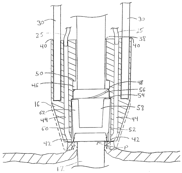
Referring now also to FIG. 2, the vascular device 10 is described in greater
detail.
The clip housing 16 includes a bore 38 that slidably receives the introducer
sheath 12,
bores 40 in which the rods 30 are mounted, and backbleed indicator ports 42.
The
backfield indicator ports 42 are coupled to the backfield tubes 25 via lumens
44. The
housing 16 also includes a threaded bore 46 with male threads 48 and a
proximal ledge 50,
and a clip bore 52 with a proximal ledge 54. The threaded bore 46 engages
female threads
56 of a clip expander 58. The clip expander 58 is slidably disposed on the
introducer
sheath 12, and, together with the portion of clip housing 16 surrounding the
clip 62, forms
an annular chamber 60.
The clip 62 is stored in its expanded delivery configuration in the annular
chamber
60 so that it slidably passes over the clip expander 58 until it abuts the
proximal ledge 54
of the clip bore 52. In a delivery configuration of the vascular device 10,
the length of the
annular chamber 60, as measured from the distal end of the clip expander 58 to
the
proximal ledge 54, extends within the distal end of the clip housing 16 for a
sufficient
distance to cover the length of the clip 62. In this manner, the clip housing
16 prevents the
clip 62 from snagging on tissue during advancement of the clip housing 16 to
its deployed
position, as described further below.
The rods 30 pass through the arc-shaped lumens 22 of the hub 14 and are
mounted
in the bores 40 of the clip housing 16. Distal advancement of the rods 30
causes the clip
housing 16, the clip expander 58, and the clip 62 to advance distally a
corresponding
distance relative to the introducer sheath 12. When the plunger 28 is moved to
its distal-
most position, the rods 30 may be rotated within the arc-shaped lumens 22 to
rotate and
advance the clip housing 16 relative to the clip expander 58. This motion
causes the clip
housing 16 to advance distally along the female threads 56 of the clip
expander 58 until
the proximal end of the clip expander 58 contacts the proximal ledge 50 of the
threaded
CA 02395235 2002-07-03
WO 01/49186 PCT/USO1/00286
-9-
bore 46. Further rotation of the rods 30 causes the proximal ledge 54 to urge
a tissue-
engaging portion of the clip 62 distally off of clip expander 58. With the
clip housing 16
positioned at a vascular puncture site P, rotation of the rods 30 causes the
tissue-engaging
portion, e.g., spikes, to pierce the vessel wall, as seen in dotted profile in
FIG. 2.
In alternative embodiments, the plunger 28 and rods 30 may be removably
coupled
to the clip housing 16, e.g., to permit unobstructed access to the device port
26. In this
embodiment, the rods 30 may include teeth that may be rotated to fixedly
engage the bores
40 in the clip housing 16.
As discussed above, the backbleed indicator ports 42 may be coupled to the
tubes
25 via the blood lumens 44 that extend through the clip housing 16. The
backfield tubes
25 are slidably disposed through the backfield lumens 24 of the hub 14. When
the distal
end of the clip housing 16 is advanced distally against the vessel wall at
puncture P, blood
may enter the blood indicator ports 42 and exit the tubes 25, providing visual
confirmation
to the surgeon that the distal end of the clip housing 16 is positioned
adjacent to the vessel
wall. Thus, the backfield tubes 25 may enable the surgeon to determine when
the clip
housing 16 has been advanced sufficiently to permit clip deployment, while
reducing the
risk that the clip 62 is either deployed short of the puncture site or
extended into the vessel.
Still refernng to FIG. l, in conjunction with clip deployment, a bioglue or
tissue
sealant may be delivered through the hemostatic port 34, tubing 36, the port
20 and the
central lumen 13 of the introducer sheath 12 to vascular puncture P to further
help seal the
vessel after deployment of the clip 62. Alternatively, the bioglue or tissue
sealant may be
delivered through the backbleed path described above.
Refernng now to FIGS. 3A-3D, an illustrative spring clip 62 constructed in
accordance with the principles of the present invention is described in
greater detail. FIG.
3B is a side view of the clip of FIG. 3A rotated 90 degrees, wherein the clip
62 is in an
expanded delivery configuration. The clip 62 includes an annular device having
upper
members 70 joined to lower members 72 by legs 74 to form a lumen 80. Outer
spikes 76
and inner spikes 78 are connected to the lower members 72, and act as
elongated tissue-
engaging members. The clip 62 is elastically expanded by advancing the
introducer sheath
12 or clip expander 58 (not shown in FIGS. 3A-3D) through the lumen 80.
Upon removal of the introducer sheath, the clip 62 resiliently returns to its
unstressed deployed configuration, illustrated in FIGS. 3C and 3D, where FIG.
3C
CA 02395235 2002-07-03
WO 01/49186 PCT/USO1/00286
- 10-
corresponds to the view of FIG. 3A and FIG. 3D corresponds to the view of FIG.
3B.
When removed from the exterior of the introducer sheath 12, the clip 62
resumes its
deployed shape, in which the opposing sides of the clip come together until
lower
members 72 contact one another, and outer spikes 76 cross inner spikes 78. As
depicted in
FIG. 3A, clip 62 also may optionally include engagement elements 77, such as
barbs or
hooks, to securely engage the vessel being closed.
The clip 62 is preferably fabricated from a superelastic material, such as a
nickel-
titanium alloy, but may include any material with sufficient resilience to
elastically expand
for delivery over the introducer sheath 12 and fit within the annular chamber
60 of the clip
housing 16 (see FIG. 2). The clip 62 may also be fabricated from a
bioabsorbable material
or a combination bioabsorbable and elastically expandable material.
FIGS. 4A and 4B illustrate an alternative embodiment of a resilient spring
clip 90
of the present invention, that includes a hoop 92 and opposing spikes 94. In
FIG. 4A, the
clip 90 is depicted in its unstressed, deployed configuration, in which
opposing spikes 94
contact one another. In FIG. 4B, the clip 90 is depicted in its expanded,
delivery
configuration, in which the opposing spikes 94 are separated by a gap 96. The
clip 90 is
elastically expanded in a manner similar to the clip 62 described above, e.g.,
by
advancement over an introducer sheath, and preferably also is fabricated from
similar
materials to those described above.
Refernng now to FIGS. SA-SF in conjunction with FIGS. 1-3, methods of using a
vascular device 10 are described. In FIG. 5A, the introducer sheath 12 has
been advanced
through skin, fat, and muscle tissue T into vessel V, through vascular
puncture P, which is
formed in accordance with well-known techniques. With the plunger 28 and rods
30 in
their proximal-most, fully retracted position, an interventional procedure
rnay then be
performed by introducing one or more interventional devices, e.g. angioplasty
balloons,
stmt delivery systems, atherectomy devices, etc., through the device port 26
and lumen 13
of the introducer sheath 12 in accordance with well known techniques. The side
port 20
may be used to infuse fluids, e.g., contrast agents or medications, into the
vessel through
the introducer sheath 12 during the interventional procedure.
Upon completion of the procedure, a clip 62 may be used to close vascular
puncture P. At this point, the clip actuator 18, the housing 16, the clip
expander 58, and
CA 02395235 2002-07-03
WO 01/49186 PCT/USO1/00286
-11-
the clip 62 are disposed in their proximal-most position adjacent to the hub
14, as depicted
in FIG. 5A.
As illustrated in FIG. 5B, the clip actuator 18 may then be advanced by urging
the
plunger 28 in the distal direction, thereby causing the rods 30 to slide
through the arc-
shaped lumens 22 of the hub 14 and advance the clip housing 16. Continued
distal
advancement of the plunger 28 causes the distal end of the clip housing 16 to
abut against
the exterior of the vessel, so that the backbleed indicator ports 42 of the
clip housing 16
directly communicate with the puncture wound. The presence of pressure in the
vessel
higher than atmospheric pressure causes blood to pass through the indicator
ports 42, the
blood lumens 44, and exit through the proximal ends of the tubes 25, thereby
confirming
that the clip housing 16 is positioned at the puncture site and should not be
advanced
further.
In FIG. SC, with the clip housing 16 held immobile, the clip actuator 18 is
rotated
clockwise within the arc-shaped lumens 22 so that the rods 30 rotate and
advance the clip
housing 16 with respect to the clip expander 58 (see FIG. 2). Specifically,
the ledge 54 of
the housing 16 contacts the proximal end of the clip 62 and drives the clip 62
distally so
that its tissue-engaging members, spikes 76, 78, contact and pierce the wall
of vessel V at
points around the puncture site, as discussed above with respect to FIG. 2.
Once the spikes 76, 78 have pierced the vessel wall, the clip actuator 18 is
rotated
counterclockwise within the arc-shaped lumens 22 to retract the clip housing
16, via the
threaded bore 46 along the clip expander 58. The tissue-engaging members 76,
78 of the
clip 62 retain the clip 62 within the wall of the vessel V while the housing
retracts, as
shown in FIG. SD.
In FIG. SE, with the clip 62 engaged with the vessel wall, the clip housing 16
and
the clip expander 58 are withdrawn proximally by proximally withdrawing
actuator 18,
thereby causing the clip 62 to slide off of the clip expander 58. In FIG. SE,
the spike 78 is
embedded in tissue not shown, because that tissue lies within the plane of the
cross
section.
The vascular device 10 may then be withdrawn from the vessel wall. Once the
introducer sheath 12 is removed from the lumen 80 of the clip 62, the clip 62
rotates
relative to the vessel wall, as shown in FIG. SF, and returns to its
unstressed, deployed
configuration, thus drawing opposite sides of puncture P together to seal the
puncture. At
CA 02395235 2002-07-03
WO 01/49186 PCT/USO1/00286
-12-
this point, a suitable biocompatible bioglue or tissue sealant optionally may
be injected
into the puncture tract, as discussed above, through the device port 26 or
side port, to aid
in sealing vascular puncture P. Alternatively, the bioglue or tissue sealant
may be
delivered through the backbleed path described above.
Turning now to FIGS. 6 and 7A, a second embodiment of an apparatus 110 in
accordance with the present invention is shown. The apparatus 110 includes an
introducer
sheath 112 coupled to a hub 114, a clip housing 116, and a clip actuator 118.
A closure
component 120, described in detail below, is disposed in the clip housing 116.
The introducer sheath 112 is formed from a material typically used for
vascular
introducer sheaths, such as polyethylene or nylon, and includes a central
lumen 113
through which other interventional devices may be introduced into the
vasculature, for
example, to perform a diagnostic or interventional procedure such as
angiography,
angioplasty, or stenting.
The hub 114 is mounted to the proximal end of the introducer sheath 112 and
includes a side port 122, actuator lumens 124, closure lumens 126, backbleed
lumens 128,
backfield tubes 130, and a device port 132. The device port 132 communicates
with the
central lumen 113 of introducer sheath 112, and has a self sealing elastomeric
membrane
133 disposed across it. The self sealing membrane 133, which may be formed
from latex
or a biocompatible synthetic rubber, may permit interventional devices to be
introduced
through the device port 132, while preventing blood loss through the central
lumen 113.
The side port 122 of the hub 114 is also in communication with the central
lumen 113, and
is connected to a hemostatic port 134 via biocompatible tubing 136.
The clip housing 116 includes two lumens 159 that each hold a bioabsorbable,
deformable clip 146. The clip housing 116 is slidably disposed on the exterior
of
introducer sheath 112 and is movable from a stowed position, adjacent hub 114,
to a distal
clip deployment position, where the bioabsorbable clips 146 are urged into
engagement
with tissue surrounding a vascular puncture (not shown). The clip housing 116
prevents
the clips 146 from snagging on tissue during advancement of clip housing 116.
The clip actuator 118 includes a plunger 138 and rods 140, which are
configured to
slidably pass through the actuator lumens 124 of the hub 114. The plunger 138
further
includes openings 139. The distal ends of the rods 140 are mounted in the clip
housing
116, so that movement of the plunger 138 causes corresponding proximal or
distal
CA 02395235 2002-07-03
WO 01/49186 PCT/USO1/00286
-13-
movement of the clip housing 116. When the plunger 138 is moved to its
proximal-most
position, the clip housing 116 is disposed adjacent to the hub 114 and
provides adequate
clearance for interventional devices to be inserted through the device port
132 and central
lumen 113 into the patient's vasculature. When moved to its distal-most
position, the
plunger 138 causes the rods 140 to urge the clip housing 116 distally.
With particular reference to FIGS. 7A-7C, the clip housing 116 includes a
lumen
142 that slidably receives the introducer sheath 112, rod bores 141 (see FIG.
6) in which
the rods 140 are mounted, clip lumens 144 in which the clips 146 are housed
and advanced
to a puncture site, pin holes 148 for rigidly receiving distal pins 150, and
backbleed
indicator ports (not shown, out of the plane of the cross-section of FIG. 7A)
that are
coupled to the backbleed tubes 130 via blood lumens 131.
The closure component 120 includes caps 152 with pin holes (not shown, out of
the plane of the cross-section of FIG. 7A) configured to receive proximal pins
154, clip
holders 156 attached to the clips 146, and locking collar drivers 158
configured to advance
fasteners 160. The locking collar drivers 158 are slidably received within
lumens 139 of
the plunger 138, the closure lumens 126 of the hub 14, and the clip lumens 144
of the clip
housing 116. The drivers 158 also include lumens 159 and square clip bores
147, in which
clip holders 156 and the clips 146, respectively, are slidably received. The
bores 147
preferably have square cross sections.
As illustrated in FIG. 7B, the locking collar drivers 158 include proximal
driver
slots 162 that communicate with lumens 159, while the clip holders 156 include
proximal
holder slots 164. The proximal pins 154, mounted in caps 152, pass through and
are
slidably received within the slots 162 and 164. As seen in FIG. 7C, the
locking collar
drivers 158 also include distal driver slots 166 that communicate with the
lumens 159,
while the clip holders 156 further include distal holder slots 168. The distal
pins 150,
mounted in the clip housing 116, pass through and are slidably received within
the slots
166 and 168.
As discussed above, backbleed indicator ports (not shown) are coupled to the
backbleed tubes 130 via the blood lumens 131 that extend through the clip
housing 116.
The backbleed tubes 130 are slidably disposed through the backbleed lumens 128
of the
hub 114. When the distal end of the clip housing 116 is advanced distally
against a vessel
wall at a vascular puncture, blood enters the backbleed indicator ports and
exits through
CA 02395235 2002-07-03
WO 01/49186 PCT/USO1/00286
-14-
the tubes 130, providing visual confirmation to an operator that the distal
end of the clip
housing 116 is positioned adjacent to the vessel wall. The backbleed tubes 130
thus
enable the operator to determine when the clip housing 116 has been
sufficiently advanced
to permit clip deployment, while reducing the risk that the clips 146 are
either deployed
short of the puncture site or extended into the vessel.
In conjunction with clip deployment, a bioglue or tissue sealant may be
delivered
through the hemostatic port 134, the biocompatible tubing 136, the side port
122 and the
central lumen 113 of the introducer sheath 112 to the vascular puncture to
further help seal
the vessel after deployment of clips 146. Alternatively, the bioglue or tissue
sealant may
be delivered through the device port 132 or through the backbleed path
described above.
With reference now to FIGS. 8A-SC, the clip 146 and fastener 160 are described
in
greater detail. FIG. 8A shows the clip 146 in its delivery configuration. The
clip 46
includes curved legs 170 and proximal end 172. The legs 170 distally terminate
at spikes
174 with optional engagement elements 176, such as barbs or hooks, and
proximally
terminate at narrowed region 178. As seen in FIG. 7A, the proximal end 172 may
be
attached to the clip holder 156, for example, using an adhesive, and is
slidably received by
the square clip bore 147 of the locking collar driver 158. As with the bore
147, the clip
146 is of substantially square cross section.
The fastener 160 includes a bioabsorbable locking collar 180, which is
slidably
received on the exterior of the clip 146. As seen in FIG. 8B, the locking
collar 180 may be
distally advanced down the exterior of the clip 146 to deform the clip 146 to
its deployed
configuration, wherein the curved legs 170 and spikes 174 are drawn together.
The clip
146 may then be separated from the clip holder 156 by rotating the proximal
end 172 with
respect to the legs 170, causing the clip 146 to snap into two pieces at the
narrowed region
178, as described below. The clip 146 and the locking collar 180 are
preferably fabricated
from bioabsorbable materials, such as polyglycolic acid.
Turning to FIGS. 9A and 9B, an alternative embodiment of a closure component
190 in accordance with the present invention is shown. The closure component
190
includes a bioabsorbable clip 192 and a fastener 194. The clip 192 includes a
proximal
hoop 196 with narrowed regions 198, and legs 200 terminating in spikes 202.
The fastener
194 includes a bioabsorbable wedge 204. The wedge 204 has a diameter
substantially
equal to the diameter of the hoop 196 at its distal end, the diameter tapering
to a maximum
CA 02395235 2002-07-03
WO 01/49186 PCT/USO1/00286
-15-
diameter at the proximal end of the wedge 204. The clip 192 therefore may be
deformed
from the delivery configuration of FIG. 9A to the deployed configuration of
FIG. 9B,
wherein the legs 200 and spikes 202 are drawn together, by advancing wedge 204
into the
hoop 196 to deform the clip 192 at the narrowed regions 198. A lumen 206
extends
through the hoop 198 of the clip 192, while a lumen 208 extends through the
wedge 196.
The clip 192 and wedge 196 are thus configured for delivery over the exterior
of an
introducer sheath (not shown). The clip 192 and wedge 196 are preferably
fabricated from
bioabsorbable materials.
With reference to FIGS. l0A-lOB through 13A-13B, in conjunction with FIGS. 6-
8C, methods of using the vascular device 110 are described. the introducer
sheath 112 is
advanced through skin, fat, and muscle tissue into vessel V, through vascular
puncture P,
which is formed in accordance with well known techniques. The vascular device
110 is
used in the same manner as a standard introducer sheath, with instruments
being advanced
into the vessel via lumen 113. Specifically, with the plunger 138 and rods 140
in their
proximal-most, fully retracted position, an interventional procedure may be
performed by
introducing one or more interventional devices, e.g. angioplasty balloons,
stmt delivery
systems, devices, etc., through the device port 132 and the lumen 113 of the
introducer
sheath 112 in accordance with well-known techniques. The side port 122 may be
used to
infuse fluids, e.g., contrast agents or medications, into the vessel through
the introducer
sheath 112 during the interventional procedure.
Upon completion of the procedure, the vascular device 110 may be used to close
the vascular puncture P. At this point, the clip actuator 118, the clip
housing 116, and the
closure component 120 with clips 146, are disposed in their proximal-most
position
adj acent to the hub 114.
The clip actuator 18 is advanced by urging the plunger 138 in the distal
direction,
thereby causing the rods 140 to slide through the actuator lumens 124 of the
hub 114 and
advance the clip housing 116. The distal pins 150, mounted in housing 116,
abut the distal
slots 166, 168 of the drivers 158 and the holders 156, respectively. Thus,
distal
advancement of the clip housing 116 also distally advances the closure
component 120.
Continued distal advancement of the plunger 138 causes the distal end of the
clip housing
116 to abut against the exterior of the vessel, so that the backbleed
indicator ports (not
shown) of the clip housing 116 directly communicate with the puncture wound.
The
CA 02395235 2002-07-03
WO 01/49186 PCT/USO1/00286
-16-
presence of pressure in the vessel higher than atmospheric pressure causes
blood to pass
through the indicator ports, through the blood lumens 131, and exit through
the proximal
ends of the tubes 130, thereby confirming that the clip housing 116 is
positioned at the
puncture site and should not be advanced further.
FIG. lOB illustrates the closure component 120 via sectional views through the
clip
housing 116 along planes parallel to the introduces sheath 112. FIG. 10A shows
the
locations of the proximal pins 154 within the proximal slots 162, 164, and the
locations of
the distal pins 150 within the distal slots 166, 168, corresponding to the
relative
longitudinal positions of the clip holders 156 and the locking collar drivers
158 depicted in
FIG. l OB. The pin locations are shown via side views of the clip holders 156
and the
locking collar drivers 158 at the relevant locations.
As seen in FIGS. 10A and 10B, with the clip housing 116 positioned at the
puncture site P, the proximal pins 154, mounted in the caps 152, are
positioned at the
extreme right of the proximal driver slots 162 and of the circumferential
portions of the
proximal holder slots 164. The distal pins 150 are located at the distal end
of the distal
driver slots 166 and of the longitudinal portions of the distal holder slots
168.
In FIGS. 11A and 11B, with the clip housing 116 held immobile, force is
applied
to the caps 152 to distally advance the clips 146 with respect to the clip
housing 116.
Specifically, the proximal pins 154 abut and apply force against the proximal
slots 162,
164, thereby advancing the drivers 158 and the clip holders 156, as well as
the attached
clips 146 and the locking collars 180. The distal pins 1 SO move freely within
the distal
slots 166 and the longitudinal portions of the distal slots 168. Distal
advancement of the
clips 146 continues until the pins 150 abut against the proximal end of the
longitudinal
portions of the distal holder slots 168 of the clip holders 156. The drivers 1
S 8 likewise are
restrained by their connection to the clip holders 156 via the proximal pins
154. The
tissue-engaging members, i.e., spikes 174 and engagement elements 176, of the
clips 146
contact and pierce the wall of the vessel V on opposite sides of the puncture
site P.
As seen in FIGS. 12A and 12B, once the spikes have pierced the vessel wall,
the
locking collar drivers 158 are advanced distally while the clip housing 116
and the clip
holders 156 remain stationary, thereby distally advancing the locking collars
180 down the
exteriors of the clips 146 to draw the legs 170 and spikes 174 together to
close the
CA 02395235 2002-07-03
WO 01/49186 PCT/USO1/00286
-17-
puncture P. Engagement elements 176 serve to retain the clips 146 within the
vessel wall
during healing.
To achieve this advancement of the drivers 158 with respect to the clip
holders
156, the caps 152 are rotated clockwise, as viewed from above, until the
proximal pins 154
abut against the extreme left of the proximal slots 162, 164, thereby aligning
the pins 154
with the longitudinal portions of the proximal holder slots 164. Force is then
once again
applied to the caps 152 to advance the drivers 158 and deform the clips 146 to
their
deployed configurations. Specifically, the proximal pins 154 abut and apply
force to the
proximal driver slots 162, thereby distally advancing the drivers 158. The
pins 154 move
freely within the longitudinal portions of the proximal holder slots 164 until
they abut
against the distal ends of the slots 164. Likewise, the distal driver slots
166 move freely
until the distal pins 150 abut the proximal ends of the slots 166. In FIG.
12A, when the
proximal pins 154 abut the slots 164 and the distal pins 150 abut the slots
166, the locking
collars 180 have been driven down the exteriors of the clips 146, thereby
deforming the
clips 146 to draw the legs 170 together and close the puncture site.
In FIGS. 13A and 13B, with the clips 146 deformed to seal the puncture P, the
clip
holders 156 are detached from the clips 146 by snapping the clips 146 free at
the narrowed
regions 178.
At this point, or prior to detachment, a suitable biocompatible bioglue or
tissue
sealant optionally may be injected into the puncture tract, as discussed
above, through the
device port 132 or the side port 122, to aid in sealing the vascular puncture
P.
Alternatively, the bioglue or tissue sealant may be delivered through the
backbleed path
described above. The vascular device 110 then is withdrawn from the vessel
wall,
completing the procedure.
The clips 146 are detached from the clip holders 156 by rotating the caps 152
counterclockwise, as viewed from above. The proximal pins 154 of the caps 152
move
freely within the proximal driver slots 162, but abut against the distal end
of the
longitudinal portions of the proximal holder slots 164 and cause the clip
holders 156 to
rotate with respect to the collar drivers 158. The distal pins 150 of the clip
housing 116
move freely within the circumferential portions of the distal holder slots 168
during
rotation of the clip holders 156. Meanwhile, the drivers 158 are restrained
from rotation
by the distal pins 150, which abut against the distal driver slots 166. The
clips 146 do not
CA 02395235 2002-07-03
WO 01/49186 PCT/USO1/00286
-18-
rotate because the square cross section of the square clip bores 147 of the
drivers 158
matches the substantially square cross section of the clips 146. Thus, since
the drivers 158
are restrained from rotation, the clips 146 are as well. Non-square cross
sections for the
clips 146 and the boresl 47 capable of performing the restraining function
will be apparent
to those of skill in the art and fall within the scope of the present
invention.
Since the clips 146 are restrained while the clip holders 156 rotate, and
since the
proximal ends 172 of the clips 146 are attached to the clip holders 156,
counterclockwise
rotation of the caps 152 causes the clips 146 to snap at their weakest points,
the narrowed
regions 178. The vascular device 110 may then be removed from the patient to
complete
the procedure.
Although preferred illustrative embodiments of the present invention are
described
above, it will be evident to one skilled in the art that various changes and
modifications
may be made without departing from the invention. For example, with minor
modifications, the vascular device 110 may be configured to carry the closure
component
190 of FIGS. 9A and 9B, or any of a variety of alternative bioabsorbable
and/or
deformable clips. The proximal pins 154 may be formed integrally with the caps
152, and
the distal pins 150 may be formed integrally with the clip housing 116. Any
number of
clips 146 may be used to close the vascular puncture.
Turning to FIG. 14, another preferred embodiment of an apparatus 210 is shown,
in
accordance with the present invention. The apparatus 210 includes 1 sheath 212
coupled
to a hub 214, a closure component 216, and 1 closure actuator 218. The sheath
212, which
may be an introducer sheath, a trocar, or a catheter, includes a central lumen
213 through
which other devices (not shown) may be introduced into the vasculature, for
example, to
perform a diagnostic or interventional procedure such as angiography,
angioplasty, or
stenting, or to seal a puncture site.
The hub 214 is mounted on the proximal end of the sheath 212 and includes a
side
port 220, arc-shaped lumens 222, and a device port 224. The device port 224
communicates with the central lumen 213 of the sheath 212, and has a self
sealing
elastomeric membrane 225 disposed across it. The self sealing membrane 225,
which may
be formed from latex or a biocompatible synthetic rubber, may permit
interventional
devices to be introduced through the device port 224, while preventing blood
loss through
the central lumen 213. The side port 220 of hub 214 is also in communication
with the
CA 02395235 2002-07-03
WO 01/49186 PCT/USO1/00286
-19-
central lumen 213, and is connected to a homeostatic port 226 via
biocompatible tubing
28.
The closure component 216 includes a lumen 230 that receives the sheath 212.
The closure component 216 is slidably disposed on the exterior of the sheath
12 and is
movable from a stowed position, adjacent the hub 214, to a distal deployment
position,
where tines 217 of the closure component 216 are urged into engagement with
tissue
surrounding a vascular puncture. The closure component 216 includes at least
two
sharpened tips or tines 217. The tines 217 preferably include backbleed ports
232. The
closure component 216 is rotatable within the arc-lumens 222 about the
longitudinal axis
of the sheath 212, so that, with tines 217 engaging tissue surrounding the
vascular
puncture, the closure component 216 may close the puncture.
The closure actuator 218 includes plunger 234 and tubes 236, which are
configured
to slidably pass through the arc lumens 222 of the hub 214. The proximal ends
of the
tubes 236 are coupled to backbleed bores 238 of the plunger 234. The distal
ends of the
tubes 236 are mounted, either permanently or detachably, in the closure
component 216,
so that movement of the plunger 234 causes corresponding proximal or distal
movement
of the closure component 216. Likewise, rotation of the plunger 234 causes
corresponding
rotation of the tubes 236 within the arc lumens 222, which, in turn, rotates
the closure
component 216 about the longitudinal axis of the sheath 212.
The plunger 234 also includes a device bore 240, coaxially aligned with the
device port 224, and through which interventional devices or puncture sealants
may be
passed. As described in detail below, when the plunger 234 is moved to its
proximal-most
position, the closure component 216 is disposed adjacent to the hub 214 and
preferably
provides adequate clearance for interventional devices to be inserted through
the device
port 224 and the central lumen 213 into the patient's vasculature. When moved
to its
distal-most position, the plunger 234 causes the tubes 236 to urge the closure
component
216 distally. Interventional devices or sealants then may be introduced
through the device
bore 240, the device port 224, and the central lumen 213 into the vasculature.
The backbleed bores 238 of the plunger 234 are in communication with backbleed
lumens (not shown) within the tubes 236. The backbleed lumens of the tubes 236
are in
communication with the backbleed ports 232 of the tines 217, thereby
establishing a
complete backbleed path through the ports 232, the lumens (not shown) of the
tubes 236,
CA 02395235 2002-07-03
WO 01/49186 PCT/USO1/00286
-20-
and the bores 238. When the tines 217 of the closure component 216 pierce a
vessel wall
surrounding a vascular puncture, blood enters the backbleed ports 232 and
exits through
the backbleed bores 238, providing visual confirmation to a surgeon that the
tines 217 are
positioned within the vessel wall. The backbleed path thus enables the surgeon
to
determine when the closure component 216 has been sufficiently advanced to
permit
rotation of the closure component 216 to close the puncture, while reducing
the risk that
the closure component 216 is either short of the puncture site or is extended
into the
vessel.
In conjunction with closure of the puncture site caused by rotation of the
closure
component 216, a puncture sealant may be introduced to the puncture site to
seal the site
closed. The sealant may, for example, include an adhesive, such as a bioglue,
tissue
sealant, or clotting agent, delivered through the hemostatic port 226, the
biocompatible
tubing 228, the side port 220 and the central lumen 213 of the introducer
sheath 212 to the
vascular puncture to further help seal the vessel after puncture closure with
the closure
component 216. Alternatively, the adhesive may be delivered through the device
port 224
or through the backbleed path described above. Instead of adhesives, the
closure
component 216 may further include the sealant, wherein the closure component
216 is left
in place within the vessel until hemostasis naturally occurs. In addition,
sutures (not
shown) may be delivered through the central lumen 213 and/or thermal energy
may be
applied, for example, from electrical induction, infrared light, ultrasonic
vibration,
microwave or laser irradiation, and other methods.
Turning to FIG. 15, an alternative puncture sealing device 250 is shown, in
accordance with the present invention. The sealing device 250 includes a
delivery device
252 and a clip 254. The delivery device 252 includes a proximal end 256
attached to a
tube 258. The tube 258 terminates at a first jaw 260 at its distal end and
includes a lumen
262 and a pin 264. The pin 264 extends into the lumen 262 from an interior
surface of the
tube 258 and is disposed perpendicular to the longitudinal axis of the tube
258. The
delivery device 252 also includes a second jaw 266 having a female connector
268 coupled
to a pin 264, so that the second jaw 266 pivots about the pin 264. The second
jaw 66
includes a moment arm 270, and a tension spring 272 is coupled to the moment
arm 270
and to the interior surface of the tube 258 in a manner that biases the second
jaw 266
against the first j aw 260.
CA 02395235 2002-07-03
WO 01/49186 PCT/USO1/00286
-21-
The first and second jaws 260, 266 preferably form a channel 274 when biased
against one another that is configured to receive the clip 254. The biasing
force applied by
the tension spring 272 holds the clip 254 within the channel 274, so that the
clip 254 may
be advanced into tissue surrounding a vascular puncture that has had its edges
approximated by the closure component 216.
The delivery device 252 also includes a plunger 276 coupled to a pushrod 278
having a release arm 280. The pushrod 278 is received within the lumen 262 of
the tube
258 such that the release arm 280 engages the moment arm 270.
Distal advancement of the pushrod 278, via application of force to the plunger
276,
causes the release arm 280 to urge the moment arm 270 distally. This motion
overcomes
the biasing force applied by the tension spring 272 and causes the second jaw
266 to pivot
about the pin 264. The second j aw 266 thus no longer contacts the first j aw
260, and the
clip 254 is released from the channel 274. The tube 258, the first jaw 260,
the second jaw
266, and the clip 254 of the sealing device 250 are preferably sized for
introduction into a
patient's vasculature through the device bore 240, the device port 224, and
the lumen 213
of vascular device 210.
Referring to FIGS. 16A-16D through 17A-17D, in conjunction with FIGS. 14 and
15, a method of using the vascular device 210 with sealing device 250 is
described. The
sheath 212 is advanced through skin, fat, and muscle tissue into vessel V,
through the
vessel wall tissue surrounding vascular puncture P. With the plunger 234 and
the tubes
236 of the actuator 218 in the proximal-most, fully retracted position, an
interventional
procedure may be performed by introducing one or more interventional devices,
e.g.
angioplasty balloons, stmt delivery systems, atherectomy devices, etc.,
through the device
port 224 and lumen 213 of the sheath 212, in accordance with well-known
techniques.
The side port 220 may be used to infuse fluids, e.g., contrast agents or
medications, into
the vessel through the sheath 212 during the interventional procedure.
Upon completion of the procedure, the vascular device 210 may be used to close
the vascular puncture P. At this point, the closure actuator 218 and the
closure component
216 are disposed in the proximal-most position, with the closure component 216
adjacent
to the hub 214. The closure actuator 218 is advanced by urging the plunger 234
in the
distal direction, thereby causing the tubes 236 to slide through the arc-
shaped lumens 222
of the hub 214 and advance the closure component 216.
CA 02395235 2002-07-03
WO 01/49186 PCT/USO1/00286
-22-
As seen in FIG. 16A, continued distal advancement of the plunger 234 causes
the
tines 217 at the distal end of the closure component 216 to pierce the tissue
surrounding
puncture P such that the backbleed ports 232 of the tines 217 directly
communicate with
the puncture wound. Tine punctures T in FIG. 17A represent the points at which
the tines
217 enter vessel V. The presence of pressure in the vessel higher than
atmospheric
pressure causes blood to pass through the backbleed ports 232, through the
backbleed
lumens (not shown) of the tubes 236, and exit through the proximal ends of the
backbleed
bores 238, thus confirming that the tines 217 have engaged tissue around the
puncture site
and should not be advanced further.
In FIG. 16B, the sheath 12 is removed from the puncture P to facilitate
closure of
the puncture P. The closure actuator 218 is held stationary while the hub 214
is withdrawn
proximally, thereby withdrawing the sheath 212 proximally from the puncture P.
The
puncture P remains open, as seen in FIG. 17B. With the sheath 212 no longer
within the
puncture P, the closure actuator 218 is rotated within the arc-shaped lumens
222 to rotate
the closure component 216. Rotation of the closure component 216 causes the
tines 217 to
rotate and urge the puncture P closed, as seen in FIGS. 16C and 17C.
Upon closure of the puncture P, a sealant is introduced to seal the wound
closed.
The sealant may, for example, include an adhesive, such as a bioglue, tissue
sealant, or
clotting agent. In addition or alternatively, a suture may be used and/or
thermal energy
may be applied. The closure component 216 may remain in place within the
vessel V until
hemostasis naturally occurs. Alternatively, a sealing device, such as one of
the clips
described herein, may be applied.
FIGS. 16D and 17D show the apparatus 210 used in conjunction with the sealing
device 250 of FIG. 15. With the clip 254 disposed in the channel 274 of the
delivery
device 252, the delivery device 252 may be delivered to the vessel V through
the device
bore 240 of the closure actuator 218, the device port 224 of the hub 214, and
the central
lumen 213 of the sheath 212. The clip 254 punctures the vessel V at tissue
surrounding
the closed puncture P, creating clip punctures C and sealing the, puncture P.
The pushrod
278 of the delivery device 252 is then actuated to separate the second jaw 266
from the
first jaw 260 to release the clip 254 from the delivery device 252. The
apparatus 210 and
the delivery device 252 are then removed from the patient to complete the
procedure. The
clip 254 maintains closure until hemostasis occurs and is preferably
bioabsorbable so that
CA 02395235 2002-07-03
WO 01/49186 PCT/USO1/00286
-23-
no foreign materials are permanently implanted in the patient's body.
Additional clips may
also be implanted, if desired or required.
With reference now to FIGS. 18A-18C, an alternative integrated vascular
apparatus
300 in accordance with the present invention is described. The Apparatus 300
includes a
sheath 302 coupled to a hub 304, a closure component 306, and a closure
actuator 308.
Similar to sheath 112 described above, the sheath 302 may be an introducer
sheath, a
trocar, or a catheter, and includes a central lumen 303 through which other
devices (not
shown) may be introduced into the vasculature, for example, to perform a
diagnostic or
interventional procedure such as angiography, angioplasty, or stenting, or to
seal a
. puncture site. The hub 304 includes a bore 310 that slidably receives the
actuator 308, a
device port 312, and a side port 314. The device port 312 is in communication
with the
central lumen 303 of the sheath 302 and permits introduction of interventional
devices
while preventing blood loss through the central lumen 303.
The closure component 306 includes an outer housing 316 having a lumen 318
configured to slidably receive the sheath 302, a bore 320 for slidably
receiving an inner
housing 322, a lumen 324 adapted to receive the closure actuator 308, and
needles or
prongs 326 with sharpened tips 328. The inner housing 322 has a lumen 323 for
receiving
the sheath 302 and channels 330 for receiving the prongs 326. The closure
component 306
includes at least two prongs 326, and preferably includes four.
The closure actuator 308 includes an actuation tube 332 having a lumen 333, an
actuation rod 334 disposed within the actuation tube 332, a first plunger 336
coupled to the
proximal end of the tube 332, and a second plunger 338 coupled to the proximal
end of the
rod 334. The distal end of the tube 332 is affixed, either permanently or
detachably, in the
lumen 324 to the outer housing 316 of the closure component 306, while the
distal end of
the rod 334 is coupled to the inner housing 322.
To perform an interventional procedure through the central lumen 303 of the
sheath 302, the sheath 302 is advanced through skin, fat, and muscle tissue
into vessel V,
through vascular puncture P, in accordance with well-known techniques. With
the closure
component 306 in its proximal-most, fully retracted position adjacent the hub
304, the
interventional procedure is then performed by introducing one or more
interventional
devices, e.g. angioplasty balloons, stmt delivery systems, atherectomy
devices, etc.,
through the device port 312 and the lumen 303 of the sheath 302, again in
accordance with
CA 02395235 2002-07-03
WO 01/49186 PCT/USO1/00286
-24-
well-known techniques. The side port 314 may be used to infuse fluids, e.g.,
contrast
agents or medications, into the vessel V through the sheath 302 during the
interventional
procedure.
Upon completion of the procedure, the apparatus 300 may be used to close the
vessel V. The closure component 306 is advanced distally by urging the
plungers 336,
338 distally. The inner housing 322 is only partially received within the bore
320 of the
outer housing 316 such that the prongs 326 are elastically deformed and
received within
the channels 330. As shown in FIG. 18A, the closure component 306 is advanced
until the
inner housing 322 abuts against the vessel V, as may be determined, for
example, with a
backbleed indicator (not shown).
In FIG. 18B, the first plunger 336 is urged distally to distally advance the
actuation
tube 332 and the outer housing 316, while the second plunger 338 and the
sheath 302 are
held stationary. Advancement of the outer housing 316 advances the sharpened
tips 328 of
the prongs 326 into tissue surrounding puncture P.
In FIG. 18C, the sheath 302 and the second plunger 338 are retracted
proximally to
draw the sheath 302 out of the vessel V and to draw the inner housing 322
completely
within the bore 320 of the outer housing 316. Proximally retracting the inner
housing 322
via the actuation rod 334 and the second plunger 338 removes the prongs 326 of
the outer
housing 316 from the channels 330 of the inner housing 322. The prongs 326
resiliently
contract to a lower stress configuration, thereby drawing opposing sides of
the puncture P
together and closing the wound. A sealant, for example, the clip 254 of FIG.
15, may then
be introduced to the closed puncture to seal the site closed, as described
above.
Alternatively, RF current, supplied by an RF generator (not shown), may be
applied across
the opposed tips 328, which may act as bipolar electrodes.
Referring to FIGS. 19A-19E, as well as FIGS. 20A and 20B, a still further
alternative embodiment of an apparatus 350 is shown, in accordance with the
present
invention. FIGS. 19A-19E depict a closure component 354 of the integrated
vascular
device in use at vascular puncture P within vessel V. The apparatus 350
includes a sheath
352 coupled to a hub (not shown), a closure component 354, and a closure
actuator (not
shown). Various closure actuators for use with the closure component 354 will
be
apparent to those of skill in the art from the foregoing embodiments.
CA 02395235 2002-07-03
WO 01/49186 PCT/USO1/00286
-25-
The sheath 352 may be an introducer sheath, a trocar, or a catheter, and may
include a central lumen 353 through which other devices (not shown) may be
introduced
into the vasculature, for example, to perform a diagnostic or interventional
procedure, such
as angiography, angioplasty, or stenting, or to seal a puncture site, similar
to the previous
embodiments. The closure component 354 includes a spacer 356, needles 358, and
a
needle cover 360. The spacer 356 is coaxially and slidably disposed about the
exterior of
the sheath 352, and preferably has an annular diameter of about one millimeter
(lmm) to
ensure that the needles 358 engage the tissue surrounding the puncture P
rather than enter
the puncture, so that the needles 358 are able to draw the wound closed, as
described
further below. The needles 358 are disposed between the spacer 356 and the
cover 360
during advancement to the puncture P. The needles 358 include ledges 362,
which act as
positive stops to prevent excessive advancement of the needles 358 with
respect to the
cover 360, which includes a corresponding annular ledge 364. The cover 360
also
includes an elastic segment 366 configured to elastically deform the needles
358. The
closure component 354 includes at least two needles 158, and preferably
includes four.
The needles 358 may further include engagement elements (not shown), such as
barbs or
hooks, to assist in gripping tissue.
As shown in FIG. 19A, the sheath 352 may be advanced through skin, fat, and
muscle tissue into the vessel V, through vascular puncture P, in accordance
with well-
known techniques. With the closure component 354 in its proximal-most, fully
retracted
position adjacent the hub 304, an interventional procedure is performed
through the central
lumen 353 of the sheath 352 by introducing one or more interventional devices
through the
lumen into the patient's vasculature. The closure component 354 is then
advanced via the
closure actuator 308 until it abuts against the vessel V, as may be
determined, for example,
with a backbleed indicator, such as that described previously. The cover 360
protects the
needles 358 and prevents snagging of tissue as the closure component 354 is
distally
advanced down the sheath 352 and through skin, fat, and muscle tissue. The
spacer 356
retains the needles 358 in a position away from the edge of the puncture P.
In FIG. 19B, the needles 358 are distally advanced with respect to the needle
cover
360 until the ledge 362 abuts the ledge 364. The needles 358 deflect the
elastic segment
366 of the cover 360 outward and pierce the tissue surrounding the puncture P.
FIG. 20A
depicts, in isometric view, the segment of the vessel V surrounding the
puncture P. With a
CA 02395235 2002-07-03
WO 01/49186 PCT/USO1/00286
-26-
needle arrangement including four needles 358, the needles 358 create needle
punctures N
surrounding the vascular puncture P. The sheath 352 and spacer 356 are then
retracted
proximally and removed from the vessel V, as shown in FIG. 19C. As depicted in
FIGS.
19D and 20B, the elastic segment 366 of the needle cover 360 resiliently
contracts, thereby
drawing the needles 358 together and approximating the edges of the wound.
A sealant, such as a bioglue, tissue sealant, or clotting agent, may then be
introduced to the puncture site to seal the wound closed. Alternatively, the
closure
component 354 may be maintained in position until hemostasis occurs naturally,
or sutures
(not shown) may be introduced through the central lumen 353. In addition, or
in the
alternative, RF energy may be applied across the needles 358, as described
above, or a
clip, such as clip 254 of the sealing device 250 of FIG. 15, may be applied.
Thermal
energy from electrical induction, infrared light, ultrasonic vibration,
microwave or laser
irradiation, and other means may also be used to seal the puncture.
Illustratively, FIG. 19E
depicts a sealing device 370, including adhesive 372, being delivered through
the central
lumen 353 within the sheath 374. After sufficient time for adhesive 372 to
set, the
apparatus 350 may be removed from the vessel V.
An integrated vascular introducer sheath with closure component of the present
invention may overcome disadvantages associated with previously known methods
and
apparatus for sealing a vascular puncture. For example, they may provide a
quick, simple,
safe, lower cost, effective, and easy-to-use solution to wound closure. An
apparatus in
accordance with the present invention may provide vascular introduction and
wound
closure in a single device, eliminating the time and manipulation required to
insert a
separate closure device at the completion of a procedure.
Although preferred illustrative embodiments of the present invention are
described
above, it will be evident to one skilled in the art that various changes and
modifications
may be made without departing from the invention. For example, with minor
modifications, vascular device 10 may be configured to carry the clip 90 of
FIGS. 4, or
any of a variety of alternative expandable resilient clips. It is intended in
the appended
claims to cover all such changes and modifications that fall within the true
spirit and scope
of the invention.