Note: Descriptions are shown in the official language in which they were submitted.
CA 02395361 2002-06-21
WO 01/47768 PCT/NO00/00447
1
Cooling water system
s
The invention relates to a system for supplying cooling water to a process on
board a floating vessel for the production of hydrocarbons, wherein the vessel
is
anchored by means of a bottom-anchored turning unit mounted in a receiving
space in
the hull of the vessel and allowing turning of the vessel about the turning
unit, and
wherein the turning unit supports a swivel unit for the transfer of
hydrocarbons from
production risers extending between the seabed and the turning unit, the
system
comprising a conduit means depending from the vessel to a depth for taking in
cooled sea
water, and a pump means for pumping of the sea water from the conduit to a
place of use
for the process.
~ s Offshore extraction and production of hydrocarbons in many cases is
carried out
on board so-called FPSO vessels, i.e. vessels constructed and built for
production, storage
and offloading of hydrocarbons (FPSO = Floating Production, Storage and
Offloading).
Such vessels are typically anchored by means of a plurality anchor lines fixed
to
anchors on the seabed and to a turning unit mounted in a receiving space in
the hull of the
Zo vessel, and allowing the vessel to turn freely about the turning unit,
under the influence of
wind, waves and water currents. The turning unit may be a submerged buoy of
the two-
part type comprising a bottom-anchored central member and an outer buoyancy
member
which is rotatably mounted on the central member and is releasably fastened in
the
receiving space in the vessel hull. As an alternative, the turning unit may
consist of a
Zs bottom-anchored turning body (turret) which is rotatably mounted in the
receiving space
by suitable bearing means, or is rotatably suspended from the deck or in the
bow of the
vessel.
As the turning unit allows the vessel to turn freely about the anchoring
point, its
central buoy member or turning body, which is stationary in relation to the
seabed,
3o supports a swivel unit for the transfer of process fluids etc. between the
relevant risers
and a pipe system on the vessel. The risers transfer oil, gas and water
between the vessel
and the seabed, and there is further arranged a so-called umbilical providing
paths for
chemicals, electric and fibre-optic signals, and electric and hydraulic power.
A process plant on board a vessel of the above-mentioned type requires supply
3s of large quantities of cooling water. A typical FPSO vessel for oil
production may use
about 5000 m3/h, and an LNG plant typically may require about 30000 m3/h. Most
FPSO
vessels today utilize a cooling water intake structure which, by means of
pumps, pulls up
sea water to a seawater intake via freely hanging, flexible hoses or conduits
extending
CA 02395361 2002-06-21
WO 01/47768 PCT/NO00/00447
2
down to a depth of maximum 40 m. As mentioned above, the vessel is anchored by
means of a plurality of anchor lines fastened to the turning unit. This
implies that the
length of the seawater intake pipes is limited to avoid interfering collisions
with the
anchor lines. From the water intake the sea water is pumped further to cooling
devices on
s the vessel. Because of the limited length of the cooling water intake pipes,
the
temperature of the intake water is almost the same as the surface temperature.
The efficiency of a process comprising cooling increases with increasing
temperature of the cooling water. The result is a lower energy consumption and
a more
efficient, and therewith less expensive equipment. As known, the temperature
of the sea
water decreases with the water depth, so that it is generally advantageous to
have the
seawater intake as deeply as possible.
The object of the invention is to provide a system for the supply of cooling
water
for the current purpose wherein the system enables a very cost-efficient and
operationally
safe construction for cooling water supply, and simultaneously enables the
supply of sea
~s water with the lowest possible temperature to the cooling systems of the
vessel.
The above-mentioned object is achieved with a system of the introductorily
stated type which, according to the invention, is characterized in that the
turning unit is
designed as a seawater swivel, the unit being provided with one or more
passages for
receiving upper end portions of respective seawater risers constituting the
conduit means,
zo and with a means for transferring sea water from the upper end portions of
the risers to an
annulus arranged at the boundary surface between mutually movable parts of the
turning
unit or between the turning unit and the vessel hull, and communicating with
one or more
passages arranged in the vessel hull and leading to said place of use, a
seawater sealing
means being arranged on each side of the annulus.
zs In the system according to the invention, the cooling water pipes are
located
within the anchoring system and are geostationary in relation to the seabed,
and thus they
will not interfere with the anchoring system and the production risers when
the vessel
turns under the influence of wind and weather. The cooling water pipes
therewith may be
extended all the way down to the seabed without interfering with the anchoring
system.
3o The cooling water is not passed through the process swivel, but is passed
directly through
the turning unit and into the vessel by the use of simple dynamic and static
seals.
The system is particularly valuable in places where the air and seawater
surface
temperatures are high. The lower cooling water temperature implies a number of
economic and environmental advantages. As to economic advantages, there may be
3s mentioned:
~ Stable annual production quantities
~ Constant cooling water temperature facilitates optimum process operation
~ Increased production in relation to power consumption
CA 02395361 2002-06-21
WO 01/47768 PCT/NO00/00447
3
~ Lower maintenance costs because of lesser fouling and corrosion tendency of
the
cold sea water
~ Lower condensation temperature for the steam turbine increases its output
~ Lower design pressure for the fractionating and cooling part of the
production plants
s ~ Reduced heat transfer surface area because of less fouling and lower OT
~ A more compact process plant design which is better suited for FPSO vessels
~ Lower cost for the process plant
As to environmental advantages, there may be mentioned:
~ Lesser COZ spill in relation to production quantity
~o ~ No chlorinating necessary
~ Practically no thermal contamination
The invention will be further described below in connection with a number of
exemplary embodiments with reference to the drawings, wherein
Fig. 1 shows a side view of a vessel which is anchored to a seabed and is
~s provided with a cooling water supply system according to the invention;
Fig. 2 shows a schematic sectional view of a first embodiment of a system
according to the invention;
Fig. 3 shows a schematic sectional view, as viewed from above, of a part of a
vessel hull with elements forming part of a system according to the invention;
zo Fig. 4 shows a schematic side view of the arrangement of Fig. 3;
Fig. 5 shows a sectioned side view of a wing tank having a suction extension
well;
Fig. 6 shows a schematic sectional view of a second embodiment of a system
according to the invention;
zs Fig. 7 shows a schematic sectional view of a third embodiment of a system
according to the invention;
Fig. 8 shows a schematic side view, partly in section, of a fourth embodiment
of
a system according to the invention;
Fig. 9 shows a side view of an embodiment essentially corresponding to the
3o embodiment according to Fig. 2;
Fig. 10 shows the detail A in Fig. 9 on an enlarged scale;
Fig. 11 shows a sectional view essentially along the line XI-XI in Fig. 10;
Fig. 12 shows a corresponding sectional view to that of Fig. 11, but of an
alternative embodiment;
3s Fig. 13 shows a sectional view of a fifth embodiment of a system according
to
the invention;
Fig. 14 shows a sectional view essentially along the line XIV-XIV in Fig. 13;
and
CA 02395361 2002-06-21
WO 01/47768 PCT/NO00/00447
4
Fig. 15 shows a corresponding sectional view to that of Fig. 14, but of an
alternative embodiment.
In the drawings, corresponding parts and elements in the different drawing
figures are designated by the same reference numerals.
s In Fig. 1 there is shown an FPSO vessel 1 floating on a water surface 2 and
being
anchored to a seabed 3 by means of a plurality of anchor lines 4. The anchor
lines at their
lower ends are connected to respective anchors 5, and at their upper ends they
are
connected to a turning unit 6 mounted in a submerged receiving space 7 at the
bottom of
the vessel. As mentioned above, the anchor lines are connected to a central
buoy member
or a turning body (turret) allowing the vessel to turn freely about the
anchoring point. As
also mentioned above, the geostationary turning body or buoy member supports a
swivel
unit (not shown in Fig. 1 ) for the transfer of, inter aria, hydrocarbons from
one or more
production risers 8 extending between the seabed 3 and the turning unit 6.
The system of the vessel 1 for the supply of cooling water to production
~ s processes on the vessel includes one or more seawater risers 9 which are
shown to extend
between the turning unit 6 and the seabed 3, and which are connected at their
lower end
to an anchoring means on the seabed, for instance a seawater lifting pump 10.
In the
illustrated embodiment, both the production risers 8 and the seawater risers 9
are shown
to comprise an upper flexible part which, at its lower end, is connected to a
buoyancy
Zo unit 11 for support of the risers, and a lower part extending between the
buoyancy unit
11 and the seabed 3. A seawater lifting pump 12 is also shown to be arranged
on the
buoyancy unit 11. The buoyancy unit 11 is moored to the seabed by means of
mooring
lines 13 connected at their lower ends to respective anchors 14.
The seawater risers 9 generally may consist of one large or several smaller
risers
zs extending down to the seabed or to a chosen depth at which the seawater
temperature is
sufficiently low. As also appears from Fig. l, the water pipes 9 between the
buoyancy
unit 11 and the seabed 3 may have the same course as the production risers 8,
or they
may extend generally vertically from the buoyancy unit to the seabed. In both
cases they
will be kept in position at the seabed by means of an anchoring means.
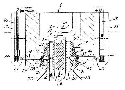
3o A first embodiment of the system according to the invention is shown in
Fig. 2.
The figure shows a cross-section of a vessel 1 provided at the bottom of the
vessel with a
receiving space 7 for the receipt of a turning unit which, in the illustrated
case, is
constituted by a two-part submerged buoy 20 comprising a bottom-anchored
central
member 21 and an outer buoyancy member 22 which is rotatably mounted on the
central
3s member. The central member is anchored by means of a suitable number of
anchor lines
23. The central member supports a swivel unit 24 which, in a usual manner, may
comprise a process swivel 25, a hydraulic utility swivel 26 and an electric
power and
control signal swivel 27. Further, the central member supports a number of
process or
CA 02395361 2002-06-21
WO 01/47768 PCT/NO00/00447
production risers 28 extending between the process swivel 25 and the seabed
(not
shown).
In accordance with the invention, the turning unit or buoy 20 is designed as a
seawater swivel, i.e. a swivel for transfernng sea water. For this purpose the
central
s member 21 of the buoy is provided with a number of passages 29 receiving the
upper end
portions or respective seawater risers 30, and with a means for the transfer
of sea water
from the risers to an annulus 31 arranged at the boundary surface between the
central
member 21 of the buoy and its outer buoyancy member 22. In the outer member of
the
buoy there is arranged a number of radial passages 32 communicating with an
additional
annulus 33 arranged at the boundary surface between the outer member 22 and
the vessel
hull 34.
As appears, the seawater risers 30 are closed at their upper end by means of a
lid
3~, and they are provided with water outlets in the form of a plurality of
holes 36
communicating with the annulus 31 between the inner and outer members 21, 22
of the
~s buoy. Outside of the outlet holes 36, the risers 30 suitably may be
surrounded by
respective annuluses communicating with the annulus 31 between the buoy
members
through a number radial passages in the inner buoy member 21.
On each side of the annuluses 31 and 33 there are arranged respective sealing
means, more specifically inner sealing means 37 and 38, respectively,
preventing leakage
zo of sea water into the space above the buoy 20, and outer sealing means 39
and 40,
respectively, preventing leakage of warmer surface sea water into the passages
for cold
water from the risers 30. As will be understood, it is here the question of
dynamic sealing
means 37, 39 between the mutually movable buoy members, and static sealing
means 38,
40 between the outer buoy member and the vessel hull.
zs In the vessel hull there are arranged a number of passages 41 extending
between
the annulus 31 and a water intake in the vessel. In the illustrated
embodiment, this water
intake is constituted by a pair of wing tanks 42 arranged on respective sides
of the vessel
1. The passages 41 lead into the wing tanks 42 via a respective valve 43, and
are
associated with a pump means 44 connected to an appurtenant conduit 45 for the
supply
30 of water in the wing tank to the relevant place of use in the production
process on the
vessel.
The annulus 33 between the outer buoy member 22 and the vessel hull 34
possibly might be omitted under the presupposition that the buoy 20 were
provided with
suitable guiding means ensuring that the buoy is introduced and secured in the
receiving
3s space with the passages 32 aligned with respective ones of the passages 41
in the vessel
hull.
As mentioned in the introduction, a process plant on an FPSO vessel requires
large quantities of cooling water, typically 5000 to 30000 m3/h. The taking-in
of such
CA 02395361 2002-06-21
WO 01/47768 PCT/NO00/00447
6
large water quantities through a swivel will require a flow area corresponding
to a pipe
having a diameter from ca. 500 mm up to ca. 2000 mm. Swivels for the transfer
of well
flows normally have a flow area corresponding to pipes having an inner
diameter from
mm up to 400 mm. Swivels for well flows have to seal completely for well flows
s having a pressure of up to 300-400 bar, because any leakage of process fluid
may be
critical. The design of such swivels and associated sealing systems requires
special
materials, strict tolerances and expensive sealing systems. A possible small
leakage in a
swivel transferring sea water is unproblematic, and a swivel for sea water may
be
designed for a low pressure (typically 1-5 bar), with simple components,
cheaper
materials and simpler sealing solutions.
The central buoy member or turret will be subjected to high loads from the
anchoring system. The turret therefore has a limited capability of accepting
pressure in a
seawater passage. However, installing the pumps in a sea water intake in a
wing tank as
shown in Fig. 1, will lower the pressure inside the turret. The turret
therefore will not be
~s unduly stressed in its application as a seawater swivel. Even if the pumps
in some cases
will have to be lowered down into the seawater risers, as described below, the
pressure of
the water can be kept very low. The extra stress on the turret can also be
kept low.
Figs. 3 and 4 show a schematic plan view and a side view, respectively, of a
part
of the elements shown in Fig. 2. As appears from Fig. 3, the passages 41
consist of six
Zo pipes of which three pipes debouch into each of the wing tanks 42 via a
respective valve
43. In each of the wing tanks there are arranged four seawater lifting pumps
44. At the
top of the conduits 45, extending between the pumps and the deck of the
vessel, there is
arranged a unit 46 for electric power supply to the associated pump.
In each of the wing tanks 42 there is also arranged an emergency water inlet
Zs means, more specifically three emergency inlets 47 communicating with the
surrounding
sea via appurtenant valves 48. The valves 43 and 48 are shown to be coupled to
a valve
handle 49 and 50, respectively, at the deck of the vessel 1, for operation of
the valves,
either manually or by remote operation. The emergency inlets are used if the
water
passages or the inlet valves 43 should be damaged, so that the cooling water
flow is
30 limited. Water flowing into the wing tanks in case of opening of the
emergency inlets,
will be water from the vicinity of the surface, and thus have a higher
temperature.
However, the process then may still be supplied with cooling water even if it
has a higher
inlet temperature.
When the inlet valves 43 in the wing tanks are opened, there will be a free
3s passage for the water from the inlet at the lower end of the seawater
risers to the wing
tanks. When the pumps 44 start working, the water level in the wing tanks
start dropping,
as suggested in Fig. 2. The difference in static height between the inside and
outside of
the seawater intake or wing tank pushes the water up through the risers 30,
through the
CA 02395361 2002-06-21
WO 01/47768 PCT/NO00/00447
7
central buoy member (turret) and through the passages and into the wing tanks.
The
water level within the wing tanks will drop until there is a balance between
the friction
losses in the pipes and passages and the pressure created by the difference in
static height
of the water. To ensure that the difference in level will not be too high, the
inside
s diameter of the seawater risers is so large that an acceptable friction loss
is generated,
estimated to 5 - 10 m of water column.
If the water level inside the water intake or wing tank is too low, the pumps
44
may cavitate and be damaged. To ensure that the pumps have a sufficient
pressure at the
inlet of the impeller, a hole can be made in the bottom of the wing tank, and
the pump
can be placed in a suction extension well in the form of a container installed
below the
tank bottom. Such an embodiment is shown in Fig. 5 wherein a container 55 is
installed
in an opening in the bottom of the tank 42 and receives a pump head 44. The
container
and the pump head may be installed from the deck and may be lifted out as a
unit if
desired. A seal (not shown) is provided between the container and the vessel
hull 34, to
~ s prevent "warm" surface water from leaking into the wing tank.
A second embodiment of the system according to the invention is shown in Fig.
6. The embodiment to a large extent corresponds to the embodiment of Fig. 2,
but the
seawater pumps here are not arranged in a water intake in the vessel. Instead
a pump 56
is arranged in each of the seawater risers 30 at a location below the buoy 20.
Electric
Zo power to the pumps is supplied as shown via the swivel unit 24 and coupling
heads 57 at
the top of the risers 30. In this embodiment, instead of the passages 41 in
the vessel hull
shown in Fig. 2, there are arranged a number of passages 58 which are
connected to
respective conduits 59 extending upwards in the space 60 above the buoy and
supplying
cooling water to the relevant place of use in the production process on the
vessel.
Zs A third embodiment of the system according to the invention is shown in
Fig. 7.
Also this embodiment to a large extent corresponds to the embodiment of Fig.
2, except
that the seawater pumps are not arranged in a water intake in the vessel.
Instead, the
relevant pumps 61 are arranged in the space 60 above the buoy 20. The pumps
are driven
by appurtenant motors (M) 62 arranged in a pump room 63 wherein also the pumps
may
3o be arranged. The pumps 61 are connected to passages or conduits 64
communicating
with the passages 32 in the outer buoy member, possibly via an annulus (not
shown), as
in the embodiment according to Fig. 2.
Fig. 8 shows a schematic, partly sectioned side view of a fourth embodiment of
a
system according to the invention. In this case the turning unit is
constituted by a bottom
3s anchored turning body (turret) 70 mounted in a receiving space 71 arranged
in a vessel 1
at a level above the water surface 72, more specifically in a hull part 73
extending
forwards from the bow of the vessel 1. The turning body is rotatably mounted
in relation
CA 02395361 2002-06-21
WO 01/47768 PCT/NO00/00447
8
to the receiving space, so that the vessel can turn freely about the turning
body. The
anchor lines for bottom-anchoring of the turning body are omitted in Fig. 8.
The turning body is provided with a number of vertical passages for receiving
the upper end portions of risers 30, these portions, in a manner similar to
the embodiment
s according to Fig. 2, being provided with a number of outlet holes 74 for sea
water. The
outlet holes communicate with radial passages 75 leading to an annulus 76
between the
turning body and the hull part 73. A pipe connection 77 is arranged between
the annulus
76 and the relevant place of use on the vessel. Dynamic seals 78 and 79 are
arranged on
each side of the annulus 76.
~o In this embodiment in which the turning body is arranged above the water
surface, the water will not flow in the system without artificial lift. The
seawater pumps
therefore must be installed within the seawater risers 30. A pump 80 is shown
to be
installed in each of the risers 30 at a sufficient depth H below the water
surface to
produce a sufficient static pressure to ensure that the pump has suitable
suction
~ s conditions. A typical distance is 10-40 m below the water surface. As the
turret and
pumps 80 are stationary in relation to the seabed, the power supply to the
pumps must
take place via the swivel unit 24 and respective junction boxes 81. In
addition to the
pumps 80, also a booster pump 82 is shown to be arranged in the pipe
connection 77.
Fig. 9 shows a sectional view of an embodiment which in all essentials
zo corresponds to the embodiment according to Fig. 2, but wherein the Figure
shows some
additional details and constructional modifications, especially in connection
with the
buoy 20. For a description of the embodiment reference is made to the
description of Fig.
2. In addition it may be remarked that the Figure also shows a locking
mechanism 85 for
releasable attachment of the buoy 20 in the receiving space in the vessel.
zs Fig. 10 shows a cutout A in Fig. 9 on an enlarged scale, and shows
construction
details in connection with the annuluses 31 and 33 and the sealing means 37-
40.
Fig. 11 shows a horizontal section along the line XI-XI in Fig. 9 and shows a
possible arrangement of production risers 28 and seawater risers 30 in the
central buoy
member 21. As shown, there are arranged seven production risers 28 and six
seawater
3o risers 30 which are distributed along respective concentric circles. Each
of the seawater
risers 30 outside of the outlet holes 36 is partly surrounded by a passage 86
communicating with the annulus 31. The annulus 31 in turn communicates with
the
annulus 33 via three passages 32.
Fig. 12 shows a sectional view corresponding to that of Fig. 11, but of an
3s alternative embodiment with respect to the connection between the riser
outlets 36 and
the passages 32. This embodiment is without individual passages (or annuluses)
in
connection with each of the seawater risers 30. Instead, the annulus 31 is
radially
CA 02395361 2002-06-21
WO 01/47768 PCT/NO00/00447
9
extended to a larger annulus 87, and placed such that the outlet openings 36
of the risers
debouch directly into this annulus.
Fig. 13 shows a sectional view of a fifth embodiment of the system according
to
the invention.
s In a manner corresponding to Fig. 8, the turning unit here is constituted by
a
turning body 70 which is rotatably mounted in a receiving space in the vessel
l, but the
receiving space here is in the form of a submerged well 90 arranged in the
bottom of the
vessel. The turning body is supported by a bearing means consisting of an
axial bearing
91 and a radial bearing 92. The turning body is anchored to the seabed by
means of a
number of anchor lines 93 (only one is shown) introduced into the turning body
via
respective guide tubes 94.
In a manner corresponding to Fig. 8, the seawater risers 30 are provided with
a
number of outlet holes 74 communicating via a number radial passages 75 with
an
annulus 76 between the turning body and the vessel hull. In this embodiment,
however, a
number of passages 4lare arranged in the vessel hull, in a manner
corresponding to the
embodiments of Figs. 2 and 9, these passages extending between the annulus 76
and a
water intake in the vessel. The water intake may be constituted by a wing tank
42 in a
manner corresponding to that of Fig. 2, wherein a pump 44 which is coupled to
a pipeline
45, is placed at the bottom of the wing tank. A corresponding water intake or
a wing tank
zo may be arranged in the vessel on the opposite side of the well 90 in
relation to what is
shown in Fig. 13.
Fig. 14 shows a horizontal section along the line XIV-XIV in Fig. 13, and
shows
a possible arrangement of production risers 28, seawater risers 30 and anchor
line
fastening points in the turning body 70. As shown, six production risers 28,
six seawater
zs risers 30 and twelve guide tubes 94 for anchor lines are arranged along
respective
concentric circles. Each of the seawater risers 30 outside of the outlet holes
74 is
surrounded by a passage or an annulus 95 communicating with the annulus 76 via
an
associated passage 75.
Fig. 15 shows a sectional view corresponding to that of Fig. 14, but of an
3o alternative embodiment with respect to the connection between the riser
outlets 74 and
the passages 75. Instead of individual passages or annuluses 95 around the
risers 30, there
is arranged a common annulus 96, so that the outlet openings 74 of the risers
debouch
directly into this annulus.
In operation of the system according to the invention, as the water flows from
3s the inlet of the seawater risers to the surface, there is generated a
difference in pressure
from the inside to the outside of the risers. This difference in pressure is
caused by the
friction losses and will increase from zero at the inlet to approximately the
difference in
CA 02395361 2002-06-21
WO 01/47768 PCT/NO00/00447
pressure caused by the difference in static head between the inside and the
outside of the
water intake/wing tank at the buoy or turret position.
The external pressure will tend to collapse the risers, and the risers will
have to
be designed with a sufficient thickness or with a suitable reinforcement to
prevent the
s risers from collapsing.
The risers will also be subjected to movements caused by the movements of the
vessel. Other forces are induced by wind, waves and forces caused by water
currents.
Due to the large diameter of the pipes and the induced movements and forces,
the risers
will be expensive to manufacture. It may therefore be more economic or more
technically
feasible to install the pumps at a sub-sea pumping station.
The pumps may be installed at the seabed or thereabove, depending on the water
depth and the optimum shape of the riser system. When the pumps are installed
inside the
risers or supply water into the risers at a certain depth, the internal
pressure in the risers
will be higher than the external water pressure above the location of the pump
unit. As
~s the riser no longer needs to be dimensioned to prevent collapse caused by
the external
overpressure, it can be made as a less expensive "soft" pipe. A "soft" pipe
will also be
less stressed by vessel movements than a rigid pipe.