Note: Descriptions are shown in the official language in which they were submitted.
CA 02395515 2002-06-21
WO 01/48514 PCT/US00/34874
BACKGROUND OF THE INVENTION
AN APPARATUS ACCURATELY MEASURING PROPERTIES OF A FORMATION
Field of the Invention
The invention is related generally to the field of electromagnetic induction
resistivity
well logging instruments wherein the induction antennas are onented
transversely with
respect to the longitudinal axis of the instrument. More specificallv, the
invention is related
to an apparatus for transverse electromagnetic induction resistivity well
logging operating
in the frequency andior time domain with reduced errors introduced into the
acquired
logging data.
Description of the Related Art
Electromagnetic induction resistivity well logging instruments are well known
in the
art. Electromagnetic induction resistivity well logging instruments are used
to determine the
electrical conductivity, and its converse, resistivity, of earth formations
penetrated by a
borehole. Formation conductivity has been determined based on results of
ineasuring the
magnetic field of eddy currents that the instrument induces in the formation
adjoining the
borehole. The electrical conductivity is used for, among other reasons,
inferring the fluid
content of the earth formations. Typically, lower conductivity (higher
resistivity) is
associated with hydrocarbon-bearing earth formations. The physical principles
of
electromagnetic induction well logging are well described, for example, in, J.
H. Moran and
K. S. Kunz, Basic Theory of Induction Logging and Application to Studv of Two-
Coil
Sondes, Geophysics, vol. 27, No. 6, part 1, pp. 829-858, Societv of
Exploration
Geophysicists, December 1962. Many improvements and modifications to
electromagnetic
induction resistivity instruments described in the Moran and Kunz reference.
supra. have
been devised, some of which are described, for example. in U. S. patent no.
4.837.517 issued
to Barber, in U. S. patent no. 5,157,605 issued to Chandler et al and in U.S.
patent no.
5,600,246 issued to Fanini et al.
The conventional geophysical induction resistivitv well logging tool is a
probe
suitable for lowerini into the borehole and it comprises a sensor section
containing a
transmitter and receiver and other, primarily electrical, equipment for
measuring data to infer
the physical parameters that characterize the formation. The sensor section,
or mandrel,
with the borehole axis. The electrical equipment generates an electrical
voltage to be further
applied to a transmitter induction coil, conditions signals coming from
receiver induction
1
SUBSTITUTE SHEET (RULE 26)
CA 02395515 2002-06-21
WO 01/48514 PCTIUSOO/34874
comprises induction transmitters and receivers positioned along the instrument
axis, arranged
in the order according to particular instrument or tool specifications and
oriented parallel
coils, processes the acquired information, stores or by means of telemetry
sending the data
to the earth surface through a wire line cable used to lower the tool into the
borehole.
In general, when using a conventional induction logging tool with transmitters
and
receivers (induction coils) oriented only along the borehole axis, the
hydrocarbon-bearing
zones are difficult to detect when they occur in multi-layered or laminated
reservoirs. These
reservoirs usuallv consist of thin alternating layers of shale and sand and,
oftentimes, the
lavers are so thin that due to the insufficient resolution of the conventional
logginQ tool thev
cannot be detected individuallv. In this case the avera,e conductivitv of the
formation is
evaluated.
Conventional induction well logging techniques employ coils wound on an
insulating mandrel. One or more transmitter coils are energized by an
alternating current.
The oscillating magnetic field produced bv this arrangement results in the
induction of
currents in the formations which are nearly proportional to the conductivity
of the
formations. These currents, in turn, contribute to the voltage induced in one
or more
receiver coils. By selecting only the voltage component which is in phase with
the
transmitter current, a signal is obtained that is approximately proportional
to the
formation conductivity. In conventional induction logging apparatus, the basic
transmitter coil and receiver coil has axes which are aligned with the
longitudinal axis of
the well logging device. (For simplicity of explanation, it will be assumed
that the bore
hole axis is aligned with the axis of the logging device, and that these are
both in the
vertical direction. Also single coils will subsequently be referred to without
regard for
focusing coils or the like.) This arrangement tends to induce secondary
current loops in
the formations that are concentric with the vertically oriented transmitting
and receiving
coils. The resultant conductivity measurements are indicative of the
horizontal
conductivity (or resistivity) of the surrounding formations. There are,
however, various
formations encountered in well logging which have a conductivitv that is
anisotropic.
Anisotropy results from the manner in which formation beds were deposited by
nature.
For example, "uniaxial anisotropy" is characterized by a difference between
the
horizontal conductivity, in a plane parallel to the bedding plane, and the
vertical
2
SUBSTITUTE SHEET (RULE 26)
CA 02395515 2002-06-21
WO 01/48514 PCT/US00/34874
conductivity, in a direction perpendicular to the bedding plane. When there is
no bedding
dip, horizontal resistivity can be considered to be in the plane perpendicular
to the
bore hole, and the vertical resistivity in the direction parallel to the bore
hole.
Conventional induction logging devices, which tend to be sensitive only to the
horizontal
conductivity of the formations, do not provide a measure of vertical
conductivity or of
anisotropy. Techniques have been developed to determine formation anisotropy.
See,
e.g. U.S. Patent No. 4,302,722. Transverse anisotrophy often occurs such that
variations
in resistivitv occur in the azimuthal direction. Techniques for addressing
such full
anisotropy are discussed in WO 98/00733.
Thus, in a vertical borehole, a conventional induction logging tool with
transmitters
and receivers (induction coils) oriented only along the borehole axis responds
to the average
horizontal conductivity that combines the conductivity of both sand and shale.
These
average readings are usually dominated by the relatively higher conductivity
of the shale
layers and exhibit reduced sensitivity to the lower conductivity sand layers
where
hydrocarbon reserves are produced. To address this problem, loggers have
turned to using
transverse induction logging tools having magnetic transmitters and receivers
(induction
coils) oriented transversely with respect to the tool longitudinal axis. Such
instruments for
transverse induction well logging has been described in PCT Patent publication
WO
98/00733 by Bear et al. and U.S. Patent Nos. 5,452,761 by Beard et al.; U.S.
Patent No.
5,999,883 by Gupta et al.; and 5,781,436 by Forgang et al.
In the transverse induction logging tools the response of transversal coil
arrays is also
determined bv an average conductivity, however, the relativelv lower
conductivitv of
hydrocarbon-bearing sand layers dominates in this estimation. In general, the
volume of
shale/sand in the formation can be determined from gamma-rav or nuclear well
logging
measurements. Then a combination of the conventional induction logging tool
with
transmitters and receivers oriented along the well axis and the transversal
induction logging
tool can be used for determining the conductivity of individual shale and sand
lavers.
One, if not the main, difficulties in interpreting the data acquired by a
transversal
induction logging tool is associated with vulnerability of its response to
borehole conditions.
Among these conditions is the presence of a conductive well fluid as well as
wellbore fluid
invasion effects. A known method for reducing these unwanted impacts on the
transversal
3
SUBSTITUTE SHEET (RULE 26)
CA 02395515 2002-06-21
WO 01/48514 PCT/US00/34874
induction logging tool response was disclosed in L. A. Tabarovsky and M. I.
Epov,
Geometric and Frequency Focusing in Exploration of Anisotropic Seams, Nauka,
USSR
Academy of Science, Siberian Division, Novosibirsk, pp. 67-129 (1972) and L.
A.
Tabarovsky and M. I. Epov, Radial Characteristics Of Induction Focusing Probes
With
Transverse Detectors In An Anisotropic Medium, Soviet Geologv And Geophysics,
20
(1979), pp. 81-90.
The known method has used a transversal induction logging tool comprising a
maQnetic transmitter and receiver (induction coils). Bv irradiating a magnetic
field the
induction transmitter induces currents in the formation adjoining the
borehole; in turn, the
receivers measure a responding magnetic field due to these currents. To enable
a wide range
of -vertical resolution and effective suppression of the unwanted borehole
effects,
measurements of ma,netic field from the formation can be obtained with
different
transmitter and receiver spacinQs that facititate geometric focusiny and
different frequencies
to facilitate frequencv focusinU. See, for example U.S. Patent No. 5,703,772
by Beard.
However, even with these modifications, the data logs obtained with a
conventional
transversal induction logging instrument can be difficult to interpret, that
has been
exacerbated while logging through a sequence of layers.
In the induction logging instruments the acquired data quality depends on the
formation electromagnetic parameter distribution (conductivity) in which the
tool induction
receivers operate. Thus, in the ideal case, the logging tool measures magnetic
signals
induced by eddy currents flowing in the formation. Variations in the magnitude
and phase
of the eddy currents occurring in response to variations in the formation
conductivity are
reflected as respective variations in the output voltage of receivers. In the
conventional
induction instruments these receiver induction coil voltages are conditioned
and then
processed using analog phase sensitive detectors or digitized bv digital to
analog converters
and then processed with siQnal processing algorithms. The processing allo'A's
for
determininU both receiver voltage amplitude and phase with respect to the
induction
transmitter current or maLynetic field waveform. It has been found convenient
for further
uphole Qeophysical interpretation to deliver the processed receiver signal as
a vector
combination of two voltage components: one being in-phase with transmitter
wavefotnl and
another out-of-phase, quadrature component. Theoretically, the in-phase coil
voltage
4
SUBSTITUTE SHEET (RULE 26)
CA 02395515 2002-06-21
WO 01/48514 PCTIUSOO/34874
component amplitude is the more sensitive and noise-free indicator of the
formation
conductivity.
There are a few hardware margins and software limitations that impact a
conventional transversal induction logging tool performance and result in
errors appearing
in the acquired data.
The general hardware problem is typically associated with an unavoidable
electrical
field that is irradiated by the tool induction transmitter simultaneously with
the desirable
magnetic field, and it happens in agreement with Maxwell's equations for the
time varying
field. The transmitter electrical field interacts with remaining modules of
the induction
logging tool and with the formation; however, this interaction does not
produce anv useful
information. Indeed. due to the always-existing possibilitv for this field to
be coupled
directly into the receiver part of the sensor section through parasitic
displacement currents,
it introduces the noise. When this coupling occurs, the electrical field
develops undesirable
electrical potentials at the input of the receiver signal conditioning,
primarily across the
induction coil receiver, and this voltage becomes an additive noise component
to the signal
of interest introducing a systematic error to the measurements.
The problem could become even more severe if the induction logging tool
operates
in wells containing water-based fluids. The water-based mud has a
significantly higher
electrical permittivity compared to the air or to the oil-based fluid. In the
same time, the
electrical impedance to the above mentioned displacement currents can be
always considered
as capacitive coupling between the source - the induction transmitter and the
point of
coupling. This circumstance apparently would result in a fact that capacitive
coupling and
associated systematic errors are environment dependant because capacitive
impedance will
be converse to the well mud permittivitv.
The conventional method in reducing this capacitive coupling in the induction
logging instrument lays in using special electrical (Faraday) shields wrapped
around both
transmitter and receiver induction coils. These shields are electrically
attached to the
transmitter analog ground common point to fix their own electrical potential
and to provide
returns of the displacement currents back to their source - transmitter
instead of coupling to
any other place in the tool. However, geometry and layout effectiveness of
Faraday shields
becomes marginal and contradictory in the high frequency applications where
conventional
5
SUBSTITUTE SHEET (RULE 26)
CA 02395515 2002-06-21
WO 01/48514 PCT/US00/34874
transverse induction tools can operate. These limitations occur due to the
attenuation these
shields introduce to the magnetic field known in the art as a shield "skin
effect". The shield
design limitations are unavoidable and, therefore, the possibility for the
coupling through
displacement currents remains.
Another source of hardware errors introduced into the acquired log data is
associated
electrical potential difference between different tool conductive parts and,
in particular,
between transmitter and receiver pressure housings if these modules are spaced
apart or
galvanically separated. These housings cover respective electronic modules and
protect
them from exposure to the harsh well environment including high pressure and
drilling
fluids. Typically, the pressure housing has a solid electrical connection to
the common point
of the electronic module it covers, however, design options with
"galvanically" floating
housings also exist. If for some reasons. mainly - imperfections in
conventional induction
tools - the common points of different electronic modules have an electrical
potential
difference between them, this difference will appear on the pressure housings.
It may occur
even in a design with "galvanically" floating housings if the instrument
operates at the high
frequencies and, in particular, through the capacitive coupling that these
metal parts might
have to the electronic modules encapsulated in a conductive metallic package.
Having different electrical potentials on separate pressure housings will
force the
electrical current to flow between them. This current would have a conductive
nature and
high magnitude if the induction tool is immersed in a conductive well fluid
and it will be a
displacement current of typically much less magnitude for tool operations in a
less
conductive or oil-based mud. In both cases this current is time varying,
therefore, it
produces an associated time varying magnetic field that is environmentallv
dependent and
measured by the induction receiver. For those who are skilled in the art it
should be
understood that the undesirable influence of those currents on the log data
would be
significantly higher in the conventional transverse induction tool compared to
the
instnunents having induction coils coaxial with the tool longitudinal axis
only. In particular,
this is due to the commonlv accepted overall design geometrv of induction
logging tools
where transmitter and receiver sections are axially separated by the mandrel.
It can be
noticed that employing the induction tool in the logginQ string where it has
mechanical and
6
SUBSTITUTE SHEET (RULE 26)
CA 02395515 2002-06-21
WO 01/48514 PCT/US00/34874
electrical connections (including telemetry) with instruments positioned both
above and
below could also result in the appearance of the above-mentioned currents.
Another source of the housings' potential offsets is the induction tool
transmitter
itself. The remaining electrical field that this transmitter irradiates
simultaneously with a
mao--netic field could be different on the surface of separate pressure
housings. Severity of
this error also depends on Faraday shields' imperfections as described
earlier.
There is an additional problem that the potential difference creates in
conventional
tool lavouts having transmitter and receiver electronic modules spaced apart
and using
intercotinection wires running throughout the sensor (mandrel) section. These
wires should
be electrically and magnetically shielded from induction receiver coils in the
sensor section.
The entire bundle of wires is placed inside of a highlv conductive metal
shield that is
electricallv connected to the common points of separated transmitter and
receiver electronic
modules. This shield's thickness is selected to enable sufficient suppression
of mutual
crosstalk between wires and sensor section coils within the entire operational
frequency
bandwidth and, primarily, at its lower end. In some cases, this shield is a
hollow copper pipe
with a relatively thick wall.
However, besides protecting the sensor section transmitter and receiver coils
and
interconnecting wires from mutual crosstalk, this shield simultaneously
creates a galvanic
path for the currents that could be driven by pressure housings and/or
electronic potential
difference. This path apparently exists along the shield's external surface.
The time varying
currents also generate a respective magnetic field that crosses induction
receiver coils and
induces error voltages. Unfortunately, these error voltages are also
environmentally
dependent and their changes cannot be sufficiently calibrated out during tool
manufacturing.
The overall analysis of the potential difference influence demonstrates that
in the conductive
well fluid, galvanic currents flowing through the fluid along external surface
of the induction
tool would dominate and, decreasing fluid conductivity redirects these
currents to flow along
the internal connection between housings. The superposition and magnitude of
these
galvanic currents strongly depend up on the ambient temperature that pushes
the
conventional induction tool performance to further deterioration.
Another source of svstematic errors introduced in the log data is directly
determined
by uncertainties in mechanical dimensions of multi-component transmitter and
receiver coils
7
SUBSTITUTE SHEET (RULE 26)
CA 02395515 2002-06-21
WO 01/48514 PCT/US00/34874
in the sensor section related both to their overall dimensions and positions
with respect to
each other. Thus, to keep required signal phase relationships, conventional
tool designs have
relied on the mechanical stability and electrical properties of advanced
ceramics and plastic
materials to build the mandrel. However, even slight phvsical assembly
deviations in the
coil wires position and non-uniform coil form material temperature
dependencies might
destroy a factory pre-set bucking (compensation of the transmitter primary
magnetic field
coupled in the receiver coil) during well logging, and create non-recoverable
errors due to
mechanical displacement or imperfections.
Another limitation found in certain induction instrumentation systems is that
an
insufficient number of signal samples that are gathered for appropriate data
stacking. Such
data insufficiencv occurs due to the necessary measurement "idle time"
required for
sequentially changing the operational transmitter frequencv in a switched
frequencv tool. It
can be demonstrated that by simply switching the transmitter frequency from
one frequency
to another requires a finite amount of decay time for spurious transient
transmitter electronic
signals to decay to a sufficiently low level to obtain accurate data
measurements. If during
this "idle time" the tool continues to take samples or measurements, these
measurements will
be inaccurate and essentially useless. Therefore, prior receiver designs have
provided for
"idle time" windows in the measurements during transient decay time, thereby
potentially
stacking a relatively small and possibly insufficient number of data samples.
A better
instrumentation design would drastically reduce required idle time. Each of
the above-
mentioned problems, by itself or a combination with another problem adds to
the data error,
thereby decreasing the accuracy of the induction downhole tool samples and
measurements.
Finally, as discussed in the U.S. Patent No. 3,124,742 by Schneider, galvanic
electrodes used
in conjunction with induction coils are useful, however, subject to the above
mentioned
problems.
SUMMARY OF THE INVENTION
It is an object of the present invention to advance the performance of
wellbore
induction logging tools operating in the frequencv andlor time domain. The
present
invention improves measurement of the formation induction response in the
presence of the
primary magnetic field generated by a logging tool's transmitter. In a
preferred embodiment
8
SUBSTITUTE SHEET (RULE 26)
CA 02395515 2002-06-21
WO 01/48514 PCT/US00/34874
of the present invention. a structure is provided having a new combination of
electrical and
mechanical design features which provide structure for high thermal stability
coil forms for
the tool's induction transmitter and receiver magnetic antenna coils, thereby
improving the
temperature stability of the antenna coil. The present invention also provides
a single coil
verification transmitter for in situ verification of the real and phase-
shifted quadrature
components of data collected by the tool durinQ operation. It is another
object of the present
invention to provide the tool sensor assembly structure that exhibits improved
symmetry in
the transmitter and receiver wiring, shielding and input circuitry to minimize
systematic
errors due to capacitive coupling of electrical field induced by the logging
tool's transmitter
signal into the tool's receiver circuitry.
It is another object of the present invention to provide electrical aroundinQ
and
isolation to the receiver and electrically isolate the receiver electronics
from the mandrel or
housing, or alternatively, provide electrical grounding to the transmitter and
let the receiver
electronics electricallv float to reduce errors caused by potential
differences between
galvanically separated receiver and transmitter housings in a logging tool.
The present
invention decreases the influence of electrical field errors by providing
floating electronics
driving transmitter coils and high-speed differential amplifiers in the
receiver signal
conditioning circuitry. Employing this combination enables a high rejection of
the parasitic
signal introduced as the common mode voltage at the receiver input. It is
another object of
the present invention to provide a sweep oscillator to obtain the primary
transmitter magnetic
field waveforms for continuous formation response sampling necessary rate
sufficient for
appropriate data stacking.
In one aspect of the invention, a logging tool is provided for measuring the
properties
of a geological formation adjacent to a borehole comprising a transmitter
comprisina at least
one coil for inducing eddy currents in the formation; a receiver comprising at
least one coil;
and an analog ground connection to at least one of the transmitter, and, the
receiver for
reducing a galvanic current flow between the transmitter and the receiver. In
another aspect
of the invention a logging tool is provided further comprising an insulator
for insulating the
receiver from electrical contact with the housiny and thus the bore hole. In
another aspect
of the invention a logging tool is provided further comprising insulating
material adjoining
the receiver. In another aspect of the invention a logging tool is provided
further comprising
9
SUBSTITUTE SHEET (RULE 26)
CA 02395515 2002-06-21
WO 01/48514 PCT/US00/34874
a tbed through pipe having an insulator between the feed through pipe and the
receiver. In
another aspect of the invention a logging tool is provided further comprising
an analog
ground connection isolated from a housing for at least one of the transmitter,
and, the
receiver. In another aspect of the invention a logging tool is provided
further comprising an
oscillator having a transmitted signal frequency swept over a frequency range.
In another
aspect of the invention a logging tool is provided further comprising a split-
coil transmitter
having bucking coil interposed between the split transmitter coils. In another
aspect of the
invention a logging tool is provided further comprising a split-coil
transmitter comprising
symmetrical coils. In another aspect of the invention a logging tool is
provided further
comprising a split-coil transmitter symmetrical shield. In another aspect of
the invention a
logging tool is provided further comprising a bucking coil shield. In another
aspect of the
invention a logging tool is provided further comprising a verification winding
for coupling
a verification signal into the receiver coil. In another aspect of the
invention a logging tool
is provided further comprising a controllable phase shifting element in the
verification check
winding to couple a controllable phase shifted and or quadrature verification
signal into the
receiver coil. In another aspect of the present invention a galvanic electrode
and current
source are housed in the same mandrel with the induction receiver and
transmitter for
complementary formation resistivity measurement and interpretation.
BRIEF DESCRIPTION OF THE DRAWINGS
Figure 1 shows schematically a wellbore extending into a laminated earth
formation,
into which wellbore an induction logging tool as used according to the
invention has been
lowered.
Figure 2A illustrates a conventional resistivity measurement in the vertical
direction.
Figure 2B illustrates a preferred resistivity measurement in the horizontal
direction.
Figure 3 is a schematic diagram illustrating a preferred embodiment of the
split coil
transmitter and bucking coil provided by the present invention.
Figure 4 is a schematic diagram illustrating a preferred embodiment of the
shielding
and electrical grounding provided by the present invention.
Figure 5 is a schematic diagram illustrating a preferred embodiment of the
current
summation and cancellation provided by the present invention.
SUBSTITUTE SHEET (RULE 26)
CA 02395515 2002-06-21
WO 01/48514 PCTIUSOO/34874
Figure 6A is a schematic diagram illustrating a preferred embodiment of the
shielding and grounding structure provided by the present invention.
Figure 6B is a schematic diagram illustrating an alternative embodiment of the
shielding and grounding structure provided by the present invention.
Figure 6C is a schematic diagram illustrating an alternative embodiment of the
shielding and grounding structure provided by the present invention.
Figure 7 is a schematic diaQram illustrating a waveform response of a
conventional
oscillator provided by the present invention.
Fiaure 8 is a schematic diagram illustrating a waveform response of the sweep
oscillator provided by the present invention.
Figure 9 is schematic representation of a preferred sensor stabilitv
verification loop
is illustrated.
Figure 10 illustrates an alternative embodiment of the invention comprising
the
induction tool along with a galvanic electrode pair on the same mandrel.
Figure 11, illustrates an alternative embodiment of the invention comprising
the
induction tool along with a single galvanic electrode on the same mandrel.
DETAILED DESCRIPTION OF A PREFERRED EMBODIMENT
The present induction well logging tool, useful during monitoring while
drilling,
logging while drilling and wireline applications, comprises a primary magnetic
field
transmitter, a receiver of the magnetic field induced by eddy currents in the
investigated
formation, a data acquisition and control system to manage the inductive
logging tool's
electronics operations, and to collect and process data. A transmitter
incorporates an
oscillator, a power amplifier driven by the oscillator and a transmitting
antenna. The
receiver electronics comprise an induction antenna and input amplifier
connected in series.
Such downhole tool applications employ induction coils for both receiver and
transmitter
antennas.
The instrument structure provided by the present invention enables increased
stability
and accuracy in an induction wellbore logging tool and its operational
capabilities, which,
in turn, results in better quality and utility of wellbore data acquired
during logging. The
features of the present invention are applicable to improve the structure of a
majority of
11
SUBSTITUTE SHEET (RULE 26)
CA 02395515 2002-06-21
WO 01/48514 PCT/US00/34874
known induction tools, those for example, designed and developed bv Baker
Atlas of
Houston, Texas. These induction tools include Baker Atlas induction tool model
numbers
1507, 1515 and 1520.
The induction logging tool modules inherently manifest a strav capacitance.
Stray
capacitive coupling between the source of a time varying electric field and a
receiver
arrangement creates significant systematic errors depending on the adjoining
tool
environment and temperature. The source of the time varying electric field
includes the
entire set of transmitter coils and cables connecting these transmitter coils
to the respective
driving transmitter electronics. The receiver arrangement typicallv consists
of a set of
receiver coils and cables connecting these coils to signal conditioning
amplifiers.
The apparatus of the present invention provides a solution to the stray
capacitance
coupling problem. The preferred structure comprises a svmmetricaliv shielded
split coil
transmitter and a bucking coil. In a preferred embodiment, the apparatus of
the present
invention provides a three axis three-coil arra_y structure wherein the main
transmitter coil
comprises two symmetrical coils wound on a single coil form and a bucking coil
electrically
connected between them. The apparatus of the present invention also provides a
structure
for symmetrically shielding the transmitter array, which maximally cancels
displacement
currents induced in the shield and enables minimization of the current return.
In a preferred
embodiment, the symmetrical shield comprises a feed through pipe as shown in
Figure 4.
Conventional applications have utilized asymmetrical induction coil arrays.
Such
asymmetrical induction coil arrays result in the necessity of asynunetrical
shielding
configurations that tend to create significant current returns in the
transmitter driving source
coil, wirina and circuitry. In conventional tool designs, this current returns
in the transmitter
braid wires in the tool electronics and in the feed through pipes used to
carrying
interconnecting wires through the tool.
The present invention solves problems encountered in conventional tools.
Typically,
conventional induction tools with feed through capabilities suffer from two
major problems
referred to as the "galvanic" driven interference problem and the "induction"
driven
interference problem. The Qalvanic problem is caused by a potential difference
between the
tool upper transmitter housing and the tool lower receiver housing. The
potential difference
between the transmitter and receiver housings is the result of multiple causes
within the tool.
12
SUBSTITUTE SHEET (RULE 26)
CA 02395515 2002-06-21
WO 01/48514 PCT/US00/34874
Such causes, include, for example, the difference in electrical ground
potentials between
housings; upper and lower housings coupling through the power transformers
connected to
the conunon AC source; capacitive coupling between the electronic switching
transmitter
power supply and the coil driving amplifiers in the pressure housing and
unshielded
electrical field irradiated by transmitter coils.
When a conventional tool operates in a conductive adjoining environment (i.e.,
borehole fluid), the potential difference between the transmitter and receiver
housings creates
a current flowing between the transmitter and receiver housings. The current
flows in the
borehole fluid in close proximity to the mandrel sensor section sleeve
containing the receiver
and transmitter coils. This induced current exhibits both the frequency and
phase of the
transmitter coil voltage, thus, the induced current generates a magnetic field
inducing error
voltaQe in the receiver coil which will be in-phase with transmitter primarv
magnetic field
and the receiver signal to be measured. This type of error can be difficult to
discriminate and
remove once it has combined with the received signal.
One may reduce this induced in-phase error by using heavy, low impedance feed
through pipe connections between metal housings with sufficient shielding of
the feed
through system communication wires. Even though this solution is somewhat
effective, it's
problematic, due to coil construction diameters versus tool diameter and
because of the
"induction" interference problem, discussed below. The induction problem
exists in
induction instruments where the upper and lower transmitter and receiver
housings are
connected by such a low impedance wire or feed through pipe during tool
operations in the
conductive borehole. In the borehole filled with conductive fluid the magnetic
field of
transmitter coils induces currents flowing in a conductive parasitic loop as
follows: upper
housing - feed through pipe - lower housing - conductive fluid and back to the
upper
housing. This parasitic current loop, in turn, induces high error voltages in
the receiver coil.
This parasitic current loop occurs due to a complex inductive coupling between
the receiver
input coil, the parasitic loop and feed through pipe.
This "induction" problem is the most severe for transverse magnetic
measurements
and is less severe in coaxial measurements. Experiments show that in some
conductive
boreholes the errors can reach up to thirty percent (30%) and more in arravs
measuring
transverse or radial magnetic field components. The present invention provides
a solution
13
SUBSTITUTE SHEET (RULE 26)
CA 02395515 2002-06-21
WO 01/48514 PCTIUSOO/34874
to the induction problem bv providing an apparatus having an electricallv
insulator or
opening to create an interruption in the conductive parasitic loop. The
insulator or opening
interrupts the induced current flowing in the parasitic conductive loop. The
parasitic
conductive loop is interrupted or opened by introducing a high impedance
separation, a
highly-resistive or an insulator material between the receiver electronics
chassis and the
receiver mandrel housing which is in contact with a conductive external
borehole fluid. The
parasitic inductive loop may also be interrupted by insertion of an insulator
between the feed
through pipe and the receiver electronics. The insulator separates the feed
through pipe from
the receiver electronics thereby interrupting the parasitic inductive current
loop.
The "gaivanic" problem is partially attributable to the difference in ground
potential.
Ground potential difference is substantially reduced bv the structure of the
present invention
by electrical grounding onl_y end of the tool electronics and leaving the
other end floating,
that is, grounding only either the receiver electronics or the transmitter
electronics in the tool.
In a preferred embodiment the receiver end of the tool is floating since the
receiver is the
most noise sensitive element in the tool. In an alternative embodiment, both
ends are
floating. In a preferred embodiment, the transmitter, receiver and galvanic
electrodes are
electrically isolated from each other.
Prior systems have provided for frequency dependent electrical isolation in
the
transmitter section through use of a capacitor. See, for example, U.S. Patent
No. 5,452,761
by Beard et al. The capacitor solution, however, sacrifices shielding at lower
transmitter
frequencies and enables induction errors, discussed above, at higher
frequencies. Moreover,
the capacitor solution assumes that higher frequency information is less
important for overall
tool performance. As it turns out, this assumption is not valid in the
transverse induction
logging tools because of the radial coil array configurations utilizing higher
frequencies
having greater susceptibility to this effect and the technical requirements
for dual frequency
measurements which render the conventional capacitor solution inadequate. The
present
invention provides a novel solution to eliminate the problem without sacricing
higher
frequency content. In the present invention, symmetrical coils and shielding
reduce the
effect of high frequency components which eliminate the need for the capacitor
for
"shorting" to ground of high frequency signals.
14
SUBSTITUTE SHEET (RULE 26)
CA 02395515 2002-06-21
WO 01/48514 PCT/US00/34874
The receiver/feed through pipe separation or insulator, is connected in close
proximity to the receiver signal conditioning amplifiers, at the most noise
sensitive section
of the measuring tool. Galvanically and electrically insulating the feed
through pipe from
the receiver electronics section enables interruption of induced currents and
enables
successful suppression of these errors. In a preferred embodiment, the
separation impedance
between the receiver section and the outer borehole environment is preferably
a minimum
of 10 kOhms in the usual operating frequency range. There are however, a wide
range of
impedances which can be controlled and selected to minimize currents and
errors in
accordance with specific operating frequencies and conditions.
The invention will now be described in more detail and by way of example with
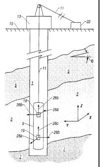
reference to the accompanying drawings. Figure 1 schematically shows a
wellbore 1
extending into a laminated earth formation, into which wellbore an induction
logging tool
as used according to the present invention has been lowered. The wellbore in
Figure 1
extends into an earth formation which includes a hydrocarbon-bearing sand
layer 3 located
between an upper shale layer 5 and a higher conductivity than the hydrocarbon
bearing sand
layer 3. An induction logging too19 used in the practice of the invention has
been lowered
into the wellbore 1 via a wire line 11 extending through a blowout preventor
13 (shown
schematically) located at the earth surface 15. The surface equipment 22
includes an electric
power supply to provide electric power to the set of coils 18 and a signal
processor to receive
and process electric signals from the receiver coils 19. Alternatively, the
power supply
and/or signal processors are located in the logging tool.
The relative orientation of the wellbore 1 and the logging too19 with respect
to the
layers 3, 5, 7 is determined by two angles, one of which 0 as shown in the
Figure 1. For
determination of these angles, see, for example U.S. Patent No. 5,999,883 bv
Gupta, et al.
The logging tool 9 is provided with a set of transmitter coils 18 and a set of
receiver coils
19, each set of coils 18, 19 being connected to surface equipment 22 via
suitable conductors
(not shown) extending along the wire line 11.
Each set of coils 18 and 19 includes three coils (not shown), which are
arranged such
that the set has three magnetic dipole moments in mutuallv orthogonal
directions, that is, in
x, v and z directions. The three-coil transmitter coil set transmits TX, TY
and T. The
receiver coil receives Rx, RY and Rz plus the cross components, Rxy, Rxz and
Rzy. Thus,
SUBSTITUTE SHEET (RULE 26)
CA 02395515 2002-06-21
WO 01/48514 PCT/US00/34874
coil set 18 has magnetic dipole moments 26a, 26b, 26c, and coil set 19 has
magnetic dipole
moments 28a, 28b, 28c. In a preferred embodiment the transmitter coil set 18
is
electrically isolated from the receiver coil set 19. In an alternative
embodiment, each coil
in transmitter coil set 18 electricallv isolated from each other and each coil
in receiver coil
set 19 electrically isolated from each other. The coils with magnetic dipole
moments 26a
and 28a are transverse coils. that is they are oriented so that the magnetic
dipole moments
are oriented perpendicular to the wellbore axis, wherebv the direction of
magnetic dipole
moment 28a is opposite to the direction of magnetic dipole moment 26a.
Furthermore the
sets of coils 18 and 19 are positioned substantiallv along the longitudinal
axis of the logging
tool 9.
As shown in FiQure 2A, conventional induction logging tools provide a single
transmitter and receiver coil that measure resistivity in the horizontal
direction. In the
conventional horizontal mode, as shown in Figure 2A. the resistivities of
adjacent high
resistivity sand and low resistivitv shale layers appear in parallel, thus the
resistivity
measurement is dominated by low resistivity shale. As shown in Figures 1 and
2B, in the
present invention a transverse coil is added to measure resistivity in the
vertical direction.
In the vertical direction, the resistivity of the highly resistive sand and
low resistivity shale
are appear in series and thus the vertical series resistivity measurement is
dominated by the
resistivity of the highly resistive sand.
For ease of reference, normal operation of the tool 9, as shown in Figures 1
and 2B,
will be described hereinafter only for the coils having dipole moments in the
x-direction, i.e.
dipole moments 26a and 28a. During normal operation an alternating current of
a frequency
fl is supplied by the electric power supply of surface equipment 22 to
transmitter coil set 18
so that a magnetic field with magnetic dipole moment 26a is induced in the
formation. In
an alternative embodiment, the frequency is swept through a range f, through
f'. This
magnetic field extends into the sand layer 3 and induces a number of local
eddy currents in
the sand layer 3. The magnitude of the local eddy currents is dependent upon
their location
relative to the transmitter coil set 18, the conductivity of the earth
formation at each location,
and the frequencv at which the transmitter coil set 18 is operating. In
principle the local
eddv currents act as a source inducing new currents, which again induce
further new
currents, and so on. The currents induced into the sand layer 3 induces a
response magnetic
16
SUBSTITUTE SHEET (RULE 26)
CA 02395515 2002-06-21
WO 01/48514 PCT/US00/34874
field in the formation, which is not in phase with the transmitted magnetic
field, but which
induces a response current in receiver coil set 19. The magnitude of the
current induced in
the sand layer 3 depends on the conductivity of the sand layer 3, the
magnitude of the
response current in receiver coil set 19. The magnitude also depends on the
conductivity and
thereby provides an indication of the conductivity of the sand laver 3.
However, the
magnetic field generated by transmitter coil set 18 not onlv extends into sand
laver 3, but
also in the wellbore fluid and in the shale layers 5 and 7 so that currents in
the wellbore fluid
and the shale layers 5 and 7 are induced.
Turning now to Figure 3, a schematic diagram of the preferred three-coil array
structure is depicted, comprising a split-coil transmitter and a bucking coil.
As shown in
Figure 3, in a preferred embodiment a symmetrical transmitter-buckinQ coil
wiring is
provided instead of the traditional coil wiring. The transmitter coil is
equallv divided into
a first transmitter coil 30 and a second transmitter coil 32. A bucking coil
33 is electrically
connected in between the first transmitter coil 30 and the second transmitter
coil 32 with
bucking coil wire extensions 34 and 35 in between first transmitter coil 30
and a second
transmitter coil 32. The same configuration can be utilized for an array
whether comprising
single or multiple transmitters and differential receivers (see, for example,
the Baker Atlas
1507 and 1515 well logging instruments). In a preferred embodiment, a
symmetrical wiring
is utilized, in a preferred point of symmetry associated with either the
center tap of the
transmitter coil driver, or with the signal ground of the receiver input pre-
amplifier. In both
cases, the shielding and routing wire reactances in cables connecting the
coils are
symmetrical with respect to both coils and the connection point, coming from
the shields
through routing wires and being already canceled or significantly suppressed
at the pre-
amplified input. Moreover, this arrangement is less sensitive to the lengthv
wires routed
along the tool and the diameter and conductivity of a feed through pipe
containing the
interconnection wirinQ.
As shown in Figure 4 the symmetrical shielding of the three-coil array enables
minimization of the current return into the transmitter or receiver thereby
introducing errors
into the collected data samples. The receiver coil 19 is shown within shield
40. Shield 40
is attached to feed through pipe 41 at point 42. Bucking coil 33 is shown
within shield 44.
Shield 44 is attached to feed through pipe 41 at point 45. Transmitter coil 18
is shown with
17
SUBSTITUTE SHEET (RULE 26)
CA 02395515 2002-06-21
WO 01/48514 PCT/US00/34874
shield 46. Shield 46 is attached to feed through pipe at point 37. Power
amplifier 43
balanced outputs 47 and 48 drive transmitter coil 18.
As shown in Figure 5, the return current, Is sums to approximately zero in the
preferred embodiment of the invention. As shown in Figure 4, the receiver
stray capacitance
associated with the receiver coil, the receiver proximate feed through pipe,
and the receiver
wiring stray capacitance is represented by capacitors 60 and 61. The current
flowing in
association with the receiver stra_y capacitance is represented by currents
IRl 62 and IR2 64
respectivelv. The bucking strav capacitance associated with the bucking coil,
the bucking
coil proximate feed through pipe, the wiring and other sources of strav
capacitance is
represented by capacitors 65 and 66. The current flowing in association with
the bucking
coil stray capacitance is represented bv currents IBl 67 and IB2 68
respectively.
The main transmitter stray capacitance associated with the main transmitter
coil, the
main transmitter proximate feed through pipe, and the main transmitter wiring
stray
capacitance is represented by capacitors 71 and 72. The current flowing in
association with
the transmitter stray capacitance is represented by currents IMl 69 and IMZ 70
respectively.
The sensor construction structure of the present invention provides
cancellation for a
summation current 17 of approximately zero, thereby reducing the error
attributable to the
induced current induction problem.
Turning now to Figure 6A, a schematic representation of a preferred embodiment
of
the shielding, grounding and isolation scheme of the present invention is
illustrated. In a
preferred embodiment the receiver 19 electronics is electrically isolated and
insulated from
the conductive pressure housing 79. The exterior of the conductive pressure
housing is in
contact with the conductive wellbore fluid. Electrical isolation of the
receiver interrupts the
induction current loop and substantially reduces the error induced into the
receiver signal
caused by induction currents flowing in conventional systems. In a preferred
embodiment
the analog ground for the main transmitter section 86 is connected to the
conductive pressure
housing 79 comprising for example. CuBe pipe. The analog ground for the
acquisition
receiver electronics is preferably separated from the conductive pressure
housing 79 bv a
high impedance in the operating frequency range, for example alOO kOhm
resistor 83 or
capacitor. This impedance. however, is preferably controlled to maximally
reduce induced
currents and associated errors. In an alternative embodiment, as shown in
Figure 6B, the
18
SUBSTITUTE SHEET (RULE 26)
CA 02395515 2002-06-21
WO 01/48514 PCTIUSOO/34874
om the
receiver electronics electrical ground is isolated by controlled high
impedance fr
conductive pressure housing and the transmitter electronics ground is
electrically connected
to the pressure housing. In another alternative embodiment, as shown in Figure
6C, both the
receiver and transmitter electronics are electronically isolated by high
impedance from the
conductive pressure housing. In another embodiment, as shown in Figure 10, a
galvanic
electrode and a current source are provided on the same mandrel and which are
electrically
isolated from the induction transmitter and receiver.
Turning now to Figure 7, an illustration of the settling time due to transient
response
91 required during conventional frequency switching is depicted. Turning now
to Figure 8,
in a preferred embodiment, a sweeping frequency oscillator is provided that
reduces transient
response 91 and therefore requires substantially less settling time, thereby
providing more
time for data acquisition and stacking of more data samples.
The conventional tool arrangement does not have to be reconfigured to
accommodate
the sweep oscillator as the majority of the electrical connections remain the
same, including
the synchronization loop and associated circuitry. Sweeping the transmission
frequency does
not prohibit dual frequency measurements as used in transverse induction
logging
instruments, in part due to the practical absence of transient time switched
processes in the
electronics. The absence of transients is useful in applications where an
extremely short time
is available for generation and measurement of each frequency-pair signals.
Turning now to Figure 9, a schematic representation of a preferred sensor
stability
verification loop is illustrated. As shown in Figure 9, power amplifier 100
accepts
verification tone reference signal 113 as input to the transmitter coil set 18
(coil set 18
comprising x, y and z-axis coils shown having magnetic dipole moments 26a, 26b
and 26c
as shown in Figure 1). When the switch 104 is in a first position and
connected to node 107,
the tone is coupled to the transmitter coils is reference loop 103 which
senses the level of the
transmitted field from transmitter coil set and sends the received signal to
the transmitter
reference channel 109 which is sent to processor 111 and subsequently sent to
surface via
telemetry 112. Durin~ logging, the reference signal is recorded to track
changes in the
transmitter current enabling subsequent removal of the effects of changes in
the transmitter
current on the received signal during logging.
19
SUBSTITUTE SHEET (RULE 26)
CA 02395515 2002-06-21
WO 01/48514 PCT/US00/34874
In a third position, switch 104 connects with node 105 wherein the signal goes
through element 114 having a variable phase shifting impedance which couples
the signal
from the transmitter coil 101 through loop 103 into the receiver coil set 19
(coil set 19
comprising x, y and z-axis coils shown having magnetic dipole moments 28a, 28b
and 28c
as shown in Figure 1). Element 114 can be selected to induce a desired phase
angle shift into
the signal in order to measure both quadrature and real component of the
signal where phase
reference is with respect to the transmitter magnetic field. In a second
position, switch 104
is connected without the loss element, thus there is no loss so that the lossy
and non-lossy
signals can be compared. This structure enables collection of quadrature
sensor stability
verification data for comparison to the quadrature component of the logging
data. The
quadrature data is significant because it is less affected by the bore hole
effects. Thus the
quadrature verification signal can be used to remove errors and effects in the
quadrature
signal to enable more accuracv in the in-phase and out of phase data acquired
durina logging.
K is the ratio of the number of turns in reference coil 103 winding MB to the
number
of turns MT in the transmitter coils 101 is small, for example 1/34. The
voltage on the single
loop 103 VB is the voltage in the transmitter coil 103 VT/K. The reflected
impedance
Zload reflected due to the single coil calibration loop 103 is equal to (K)
(ZB) where ZB is the
impedance of the single loop 103. The total transmitter impedance is eual to
ZT +
Zload reflecced= K is 1/34 in a preferred embodiment, therefore K2 is small
causing Zloaa reflecced
to be small. Thus, the inductance on the transmitter does not change
appreciably when
switching between the first, second and third positions.
Turning now to Figure 10, illustrates an alternative embodiment of the
invention
comprising the induction tool along with a galvanic electrode and current
source on the same
mandrel with the induction transmitter 18 and receiver 19. As shown in Figure
10 galvanic
electrodes 120 and 121 are housed on mandrel 130 along with induction
transmitter 18 and
induction receiver 19. In this configuration the galvanic electrodes 120 and
121 perform
lateral or differential measurements. The galvanic frequency range is
preferably 1Hz tolkHz,
but not exclusive of other frequencv ranges which are acceptable. The
induction frequency
range is from 1kH to 5Mz, but not exclusive of other frequency ranges which
are acceptable.
Preamp 110 has ground 131 and provides an output signal to an analog to
digital converter
123 which is electrically isolated from main controller 111 by capacitive and
galvanic
SUBSTITUTE SHEET (RULE 26)
CA 02395515 2002-06-21
WO 01/48514 PCTIUSOO/34874
isolator 125. Preamp 124 has ground 132 and provides an output signal to an
analog to
digital converter 128 which is isolated from main controller 111 by capacitive
and galvanic
isolator 126. In a preferred embodiment, ground 131 and 132 are isolated from
the pressure
housing. In an altemative embodiment ground 131 is electrically connected to
the pressure
housing and ground 132 is isolated from the main housing. In an alternative
embodiment
ground 132 is electrically connected to the main pressure housing and ground
131 is isolated
from the main housincy.
Turning now to Figure 11, an alternative embodiment of the invention is shown
wherein galvanic electrode 120 is located on the mandrel with the induction
tool and
galvanic electrode 121 is located at infinity with respect galvanic electrode
120, to
facilitate performing normal galvanic measurements.
21
SUBSTITUTE SHEET (RULE 26)