Note: Descriptions are shown in the official language in which they were submitted.
CA 02395740 2002-07-26
Plastic Gutter System and Components Therefor
Field of the Invention
The invention relates to gutter systems that may be assembled and secured to a
building
for catching and channelling rainwater.
Background
Rainwater gutter systems for buildings are traditionally made from metal or
plastic.
Gutter systems made of plastic offer significant benefits over those made of
metal in
terms of durability and appearance. There are a number of problems associated
with
plastic gutter systems however.
One problem with plastic gutter systems is that the plastic tends to expand,
contract or
otherwise deform in temperature extremes. A typical plastic gutter system that
spans up
to 40 ft. may experience expansion or contraction of 1" or more over diverse
climatic
conditions. In addition, plastic gutter systems can become permanently
deformed when
exposed to extreme temperature conditions.
Conventional plastic gutter systems use various structures of joints and seals
to attempt to
provide a watertight seal while permitting the gutter section to slide within
the joint as it
undergoes expansion and contraction. Examples of such systems are disclosed in
US
patents Nos. 4257716, 4297053, 4313693, 4954015, 5035092, 5038528 and 5687510.
A
problem with these systems is that the gutter sections are still relatively
pliable and are
not adequately secured in the joints to deter deformation. Thus, over a period
of time, the
gutter sections tend to deform and shift from the joints to a sufficient
extent that the
gutter system leaks.
The problem is compounded by consumer preference for a "K style" gutter that,
by virtue
of its shape, is not effectively sealed using conventional joint and gasket
systems. The
conventional "K-style" gutter also tends to allow debris to collect within the
gutter which
reduces the effectiveness of the gutter system.
Another problem with conventional gutter systems is the manner in which
downspouts
are mounted to walls. Generally, an adjustable metal strap is wrapped around
the
downspout and mounted to the wall surface with screws on either side of the
downspout.
CA 02395740 2002-07-26
Examples of such mounting systems are disclosed in US Patent Nos. 4,632,342
and
5,794,348. A problem with these systems is that the mounting fasteners are
exposed and
unsightly and the mounting attachments do not allow for simple installation
and
temporary disassembly of the downspout installation.
Another problem with conventional gutter systems is the manner in which the
drainpipe
is connected to the downspout. Conventional gutter systems employ a downspout
to
deliver water from the roof level gutters to ground level. The downspout is
typically
connected to a drainpipe that extends along the ground away from the building
for
delivering water to a desired location for drainage. A problem with
conventional
connectors is that they do not allow sufficient flexibility in the movement of
the
drainpipe. This causes inconvenience where the positioning of the drainpipe
interferes
with household chores such as lawn mowing and raking of leaves.
Accordingly, there is a need for an improved gutter system, and components
thereto, that
overcome one or more of the above identified problems.
Summary of the Invention
According to one aspect of the present invention there is provided a gutter
section for use
in a rain gutter system, the gutter section comprising an inner wall defining
a channel for
receiving and channelling rain water, and an outer wall spaced from said inner
wall to
define a substantially hollow area between the inner wall and the outer wall.
According to another aspect of the claimed invention there is provided a
gutter section for
use in a rain gutter system comprising:
~ an inner wall defining a channel for receiving and channelling rain water;
~ an outer wall defining a desired aesthetic outer shape for said gutter
section; and
~ a heat sink between said inner wall and said outer wall to deter substantial
expansion
and contraction of said gutter under ranging thermal conditions.
According to another aspect of the claimed invention, there is provided a
gutter system
comprising:
2
CA 02395740 2002-07-26
(a) a plurality of gutter sections defining a channel for receiving and
channelling rain
water; and
(b) a plurality of joint members for joining said gutter sections, each
including an
outer sleeve and an inner sleeve defining a passageway corresponding in shape
to
S a substantial portion of the cross-sectional shape of said gutter sections
for
slidably receiving at least one of said gutter sections.
According to another aspect of the claimed invention, there is provided a
joint member
for adjoining one or more gutter sections of a gutter system, the joint member
comprising:
(a) an outer sleeve and an inner sleeve received defining a passageway
corresponding in shape to a substantial portion of the cross-sectional shape
of a
gutter section for slidably receiving said gutter section; and
(b) a gasket assembly having a gasket and an attachment member for supporting
said gasket and attaching said gasket assembly to said joint member.
According to another aspect of the claimed invention, there is provided a clip
for
attaching a downspout to a wall, said clip comprising first and second clip
members, at
least one of said clip members having a means for attaching said clip to said
wall, each of
said clip members having a releasable interlocking device for releasably
interlocking said
clip members together around the downspout.
According to another aspect of the claimed invention, there is provided a
drainpipe
connector system for connecting a downspout to a drainpipe, the drainpipe
connector
system comprising:
~ a downspout connector including a first end and a second end, said first end
being
shaped for slidably engaging a downspout; and
~ a hinge member having a first portion that is hingeably connected to said
second
end of said downspout connector and a second portion that is shaped for
slidably
engaging a drainpipe, the hinge member being rotatable relative to the
downspout
connector between a raised position and a lowered position; and
3
CA 02395740 2002-07-26
~ a locking tab disposed on one or both of said downspout connector and said
hinge
member for releasably locking said hinge member in said raised position.
Description of the drawings
Figure 1 is an exploded perspective view of a gutter system in accordance with
the
present invention;
Figure 2 is a sectional view of a gutter section for the gutter system of
Figure 1 as viewed
along lines 2-2 of Figure 1;
Figure 3 is an exploded perspective view, with a portion cut away, of a joint
member and
gasket assembly for the gutter system of Figure l;
Figure 4 is a perspective view of a first corner joint member for the gutter
system of
Figure 1;
Figure 5 is a perspective view of a second comer joint member for the gutter
system of
Figure 1;
Figure 6 is a perspective view of a downspout joint member for the gutter
system of
Figure 1;
Figure 7 is a perspective view of a hanger for the gutter system of Figure 1;
Figure 8 is an exploded perspective view of a downspout clip for the gutter
system of
Figure 1; and
Figure 9 is a perspective view of a downspout connector for a drainpipe hinge
assembly
for the gutter system of Figure 1;
Figure 10 is a perspective view of a hinge member mounted to the downspout
connector
for the drainpipe hinge assembly of Figure 9; and
Figure 11 is a perspective view of the hinge member of Figure 10.
Detailed Description of the Preferr~ Embodiment
4
CA 02395740 2002-07-26
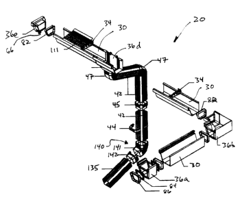
A gutter system 20 in accordance with the present invention is shown in Figure
1. The
gutter system 20 comprises a plurality of gutter sections 30 that are each
supported and
secured to a building (not shown) by hangers 34. The gutter sections 30 are
adjoined
using joint members 36. The gutter system 20 also includes downspout sections
42 that
are secured to the building with downspout clips 44. The downspout sections 42
are
adjoined using downspout joint members 45 and elbows 47. A lockable hinge
assembly
140 pivotably connecting a drainpipe 135 to a downspout section 42 is also
provided.
Referring to figure 2, gutter section 30 is shown in cross section. Gutter
section 30 has a
front side 38, a base 40 and a rear side 46. The gutter section 30 has a
continuous inner
wall 48 that defines a channel 49 for channelling rainwater along the gutter
section 30.
The gutter section 30 also has an outer wall 50 that is spaced from the inner
wall 48 by a
plurality of longitudinally extending ribs 52 to form a substantially hollow
space 53
between the inner and outer walls 48, 50. The ribs 52 preferably extend at
right angles to
the walls 48, 50 in order to optimize the rigidity of the overall structure.
The thickness of
the ribs 52 is preferably less than the thickness of the walls 48, 50 to
optimise the
construction of gutter section 30 using an extrusion process.
The hollow space 53 defined between walls 48, 50 of gutter section 30 acts as
a heat sink
to reduce the sensitivity of the gutter section 30 to extreme temperatures.
The ribs 52 add
strength to the overall structure and enhance the ability of the gutter system
to withstand
permanent deformation when subjected to heavy snow loads and ice build-up.
Also the
strength and rigidity provided by the ribs 52 is helpful for home renovation,
maintenance
and repair applications where it is desired that the gutter section 30 support
the weight of
a ladder.
It is contemplated that the gutter section 30 could be formed without ribs 52
and that
structural support and heat sink functionality can be accomplished by
disposing an
alternate material in the hollow space 53 such as a cellular foam material. It
is also
contemplated that hollow space 53 could be left unfilled although the benefits
of rigidity
will be lessened due to the absence of ribs 52 or other suitable structural
support.
The channel 49 defined by inner wall 48 of gutter section 30 has radiused
inner corners
54,56 which reduce the likelihood of debris becoming caught in channel 49. The
outer
wall 50 preferably defines an aesthetically pleasing shape as desired for the
gutter system
5
CA 02395740 2002-07-26
20. The outer wall 50 of the embodiment depicted in the figures has a recessed
edge 58
and a conventional "k-style" profile.
Gutter section 30 includes a first hanger attachment member 62 and a second
hanger
attachment member 64 which engage corresponding attachment members 108 and 110
on
hanger 34 as shown in Figure 8 and described in more detail below.
The gutter sections 30 are preferably constructed of a plastic material.
Preferably, the
gutter sections are made of vinyl using an extrusion process. The twin wall
ribbed
structure of gutter sections 30 reduces the cost of production relative to
conventional
gutter sections designed with a solid profile because less raw material is
required to
manufacture gutter sections 30 without sacrificing rigidity.
Referring to Figures 3-6, joint members for joining gutter sections 30 are
shown generally
at 36. A joint member for joining straight sections of gutter sections 30 is
shown at 36a
in Figure 3. Joint member 36 has an inner sleeve portion 63 and an outer
sleeve portion
65. Inner sleeve portion 63 is positioned to slidably fit inside and adjacent
to a
substantial portion of the inner wall 48 of the gutter section 30. The outer
sleeve portion
65 is positioned to slidably fit outside and adjacent to a substantial portion
of the outer
wall 50 of the gutter section 30. The inner sleeve portion 63 and the outer
sleeve portion
65 therefore define a passageway 66 between them for receiving and enveloping
a
substantial portion of an end of the gutter section 30. Preferably, the
passageway 66 has
tapered edges 67 to guide the end of the gutter section 30 in place. An
abutment 68 is
disposed in the passageway 66 against which the end of the gutter section 30
abuts.
The joint members 36 have passageways 66 at both ends for receiving gutter
sections 30.
In this manner joint members 36 connect the gutter sections 30 end to end. The
joint
member 36 effectively envelopes the end of gutter section 30 to deter
deformation of the
gasket section 30.
Joint member 36 also includes support rings 72 that are disposed along inner
sleeve
portion 63 at both ends of the joint member 36. The support rings have first
and second
opposing walls 73 and 75 that define a groove 77 between them. Attachment
apertures
79 are defined in second wall 75 of support ring 72 for receiving attachment
tabs 98 of a
6
CA 02395740 2002-07-26
gasket assembly 82 as detailed below. First wall 73 of support ring 72 also
defines a first
gasket locking recess 81 as described below.
Gasket assembly 82 has a gasket 84 and an attachment ring 86. The gasket 84
has a
double headed locking tab 88 and a double neck 90. The attachment ring 86 has
a tongue
94, a collar 96 and attachment tabs 98. A second gasket locking recess 99 is
defined in
collar 96. Each of the tabs 98 of attachment ring 86 are positioned to
lockably engage
attachment apertures 79 on the support ring 72. Gasket 84 is preferably made
of rubber,
EPDM or other sealing materials that are sufficiently durable for exterior
applications.
Neck 90 of gasket 84 is removably secured around the tongue 94 of attachment
ring 86
and is secured in place between collar 96 and first wall 73 of gasket ring 72
when the
attachment ring 86 is lockably engaged within groove 77 of support ring 72.
Locking tab
88 engages locking recesses 81 and 99 when the gasket 84 is secured to support
ring 72
using attachment ring 86.
This gasket assembly 82 ensures that the joint between gutter sections 30 and
joint
member 36 is substantially sealed against water leakage. The gasket assembly
82 also
ensures that the gasket 84 stays in place when the gutter system 20 is
installed and on an
ongoing basis when it is subjected to repeated movement of the gutter sections
30 caused
by ongoing periods of thermodynamic expansion and contraction of the gutter
system 20.
Further embodiments of joint members are shown in Figures 4-6. Figure 4 shows
a joint
member 36b that is adapted to join two corner gutter sections. The embodiment
shown in
Figure 4 has an outside corner 92 that defines a 90° angle. Figure 5
shows an alternate
embodiment 36c that has an outside corner 93 that defines a 135° angle.
Figure 6 shows
a further embodiment 36d of a joint member that is adapted to join a gutter
section that
has a downspout. The joint member 36d has a front flange 95, a rear flange 97
and a
tapered drainage section I00 leading to a drop outlet 101. The joint member
36d has
apertures 102 for receiving fasteners (not shown) for fastening joint member
36 directly
to a building. Flanges 9S and 99 are configured to slidably engage gutter
sections 30
without the need for a gasket assembly 82 (since drainage section 100 will
serve to catch
rain water from the end of gutter sections 30).
Figure 1 also shows a fiuther embodiment of joint member 36 in the form of an
end cap
36e. End cap joint member 36e includes passageway 66 for receiving the end of
a gutter
7
CA 02395740 2002-07-26
section 30 as described for joint member 36a above. End cap joint member 36e
also
includes a gasket assembly 82 for securely sealing the end of the gutter
section 30.
Joint members 36 are preferably constructed from a plastic material using an
injection
moulding process. While it is contemplated that plastic joint members 36 will
be used to
support plastic gutter sections 30 it is possible that the joint members 36
could be used to
support gutter sections 30 could be constructed of metal.
Referring to figure 7, a perspective view of a hanger 34 is shown. The hanger
34 has a
rear wall 104 which can be fastened to the building with nails or screws
disposed through
aperture 105. The hanger has a base 106 and attachment members 108, 110 for
engaging
first and second hanger attachment members 62,64 of the gutter section 30. The
hanger
also has upper flanges 107 and 109 for engaging a leaf screen 11 I as shown in
Figure 1.
Referring to figure 8, a downspout clip 44 is shown. The downspout clip 44 has
a first
clip member 112 and a second clip member 114. The first and second clip
members each
have male locking members 116 and female locking members 118. The male locking
members 116 each have an engaging member 120 having teeth 122. The female
locking
members 118 have a receiving mechanism 124 having angular receivers 128
corresponding to the teeth 122 of the engaging member 120 of male locking
member I 16.
The engaging member 120 is received in the receiving mechanism 124 of female
locking
member 118 to form an interlock. The male and female locking members 116, 118
are
preferably of reverse orientation relative to each other. However, other
embodiments are
also possible where the orientation of the locking members is the same. For
example, the
clips may be connected at one side by a hinge thus removing the necessity for
the locking
members to be of reverse orientation.
Each of the clip members 112,114 has an inner surface 126 and an outer surface
129. A
sealed aperture 132 is formed on the inner surface 126 of each of the clip
members
112,114. The aperture may be broken for receiving a screw or nail in order to
facilitate
the mounting of one of the clip members 112,114 to the side of the building.
Thus, one of the clip members 112, 114 is mounted to a wall or other surface
of a
building with a screw or nail (not shown) through the aperture 132. The
downspout
section 42 is placed in the clip member I 12, 114 and other the clip member I
12, 114 is
8
CA 02395740 2002-07-26
preferably reversed in orientation and slid in place over the mounted clip
member 112,
114. As the inner surface 126 of the second clip member 114 is pushed tight
against the
downspout 42, the teeth 122 on the clip members 112,114 interact to lock the
clip
members 112,114 together. The adjustable locking member 116, 118 work over a
range
of distance that can effectively compensate for both flat wall surfaces and
wall sections
with overlapping longitudinal sections.
Referring to Figures 9-11, a lockable drainpipe hinge assembiy 140 is shown.
The hinge
assembly has a downspout connector 141 for connecting to a downspout 42 and a
hinge
member 142 for slidably engaging a drainpipe 135 in a friction fit.
Pins 144 are disposed inwardly on an interior surface 146 of the hinge member
142.
Preferably there are two pins 144. One or more pins are possible in other
embodiments.
In other embodiments the interior surface 146 may define recesses for
receiving pins that
are disposed on the downspout connector 14I .
The hinge member 142 has an opening 150 defined between pins 144 to provide
sufficient clearance for the hinge member 142 to pivot about the pins 144 when
the pins
144 are connected to openings 152 in the downspout connector 141 as discussed
below.
A peripheral edge 154 of hinge member 142 is engaged by tab 156 on downspout
connector 141 as detailed below to lock the hinge member 142 in place.
Downspout connector 141 has downspout connecting portion 158 for slidably
engaging a
downspout section 42 and a hinge connector portion 160 that connects to hinge
member
142. The downspout connector 141 defines openings or recesses 152 for
receiving pins
144. A resilient tab 156 is located on the surface of the downspout connector
141 for
releasably engaging the peripheral edge 154 of the hinge member 142.
In operation, hinge member 142 is attached to the hinge connector portion 160
of
downspout connector 141 such that pins 144 are received in the openings 152.
Pins 144
and openings 152 are proportioned such that the pins 144 are rotatabIe in the
openings
152. The hinge member 142 is pivotable between a lower position where the
drain pipe
is substantially lowered to the ground and a raised position where the drain
pipe is
substantially raised from the ground. The tab 156 releasably engages the
peripheral edge
154 to retain the hinge member 142 in the raised position.
9