Note: Descriptions are shown in the official language in which they were submitted.
CA 02396254 2002-07-03
DESCRIPTION
ARRANGEMENT FOR REMOVING DENTS IN SHEET METAL
For removing concave dents from sheet metal it is known to bond an adapter
into the
dent and fit to said adapter a rod on which a slide block can be slid against
a stop.
Said slide block is referred to as a slide hammer. The slide hammer is then
struck
away from the dent in the direction of the body of the user and as a result
the dent is
drawn out of the metal sheet. The handling of said slide hammer is made
somewhat
more difficult, because it has to be struck in the direction of the body.
A sheet metal working device is already known (DE 296 1 S 666 Ul ), in which
an
adapter connectable in tension-proof manner to the lever can be slid along the
latter.
The front end of the adapter is welded to the dent and then the dent can be
drawn out
with the aid of the lever.
The problem of the invention is to create a possibility of removing dents from
a metal
sheet in a similar way.
To solve this problem the invention proposes an arrangement having the
features of
claim 1. Further developments of the invention form the subject matter of the
dependent claims, whose wording is by reference made into part of the content
of the
description.
The tension element is fitted to the adapter, which is fixed in the dent in
the same way
as in the prior art and said tension element is then connected by its other
end to the
Garner. Tensile force can then be applied to the tension adapter by means of
the
carrier. The holding element can be supported at a suitable point, e.g. on the
metal
sheet, or on an edge or some other component.
In particular, according to a further development of the invention, the
holding element
is constructed as a lever, so that it can be raised about the support point,
so as in this
way to exert a tensile force on the tension element and therefore on the
adapter
-1-
CA 02396254 2002-07-03
bonded into the dent. The handling of said device is much simpler than in the
prior
art.
The lever can be a one or two-arm lever.
According to a further development of the invention, the carrier is
constructed as an at
least partly linearly directed rod or rail. The rod or rail can have an
elongated cross-
section, so as to be particularly stable in the direction in which the force
is applied
without rendering the weight excessive. Through the construction as a lever it
is
possible to achieve high forces with the arrangement, without having to
support the
same by an impact implement.
According to a further development of the invention, the tension element can
be fitted
at different positions to the Garner, which makes it possible to position the
support
point in accordance with the circumstances at the repair location.
According to the invention, the holding element can have a handle.
According to a further development of the invention, the tension element can
be
constructed in such a way that it can be fitted in captive manner to the
Garner.
However, it is also possible to fit it in such a way that it is fixed in a
specific position
from which it can then be moved into other positions. It is also possible to
design the
carrier in such a way that the drawing piece can be removed therefrom in a
specific
position.
Further features, details and advantages of the invention can be gathered from
the
following description of a preferred embodiment of the invention and the
attached
drawings, wherein show:
Fig. 1 Diagrammatically an arrangement according to the invention for removing
a
dent from a piece of sheet metal.
-2-
CA 02396254 2002-07-03
Fig. 2 Diagrammatically the side view of the tension element used with the
arrangement.
Fig. 3 On a larger scale the fitting of the tension element to the holder
corresponding to a cross-section through the arrangement of fig. 1.
Fig. 4 A cross-section through the lower end of the tension element of fig. 2.
Fig. S A detail view of an insertion point for the tension element.
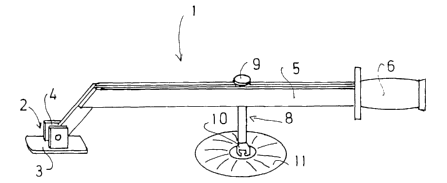
Fig. 1 perspectively shows an arrangement for removing a concave dent from a
metal
sheet according to the invention. The arrangement contains a holding element
1,
which is at one end supported on a support point 2. The support point 2
contains a flat
plate 3, which is placed on a corresponding stable point. On its underside the
plate 3
can have a coating preventing sliding or slipping away, e.g. of an elastomeric
material. In a joint arrangement, the Garner constructed as a one-arm lever is
articulated to the support 2. The Garner 1 is constructed over a large part of
its length
as a linear rail, which has two cross-sectionally rectangular, parallel,
mutually spaced
metal sections 5. At the end opposite to the support point 2 is fitted to the
holding
element 1 a handle 6, which can be gripped by a user.
The shaft 7 of a tension element 8 is passed between the two metal sections 5.
The
head 9 of the tension element 8 has a larger diameter than the spacing between
the
two metal sections 5, so that the tension element 8 is connected in tension-
proof
manner to the Garner.
At its opposite, lower end the tension element is provided with a claw 10,
with which
it can be hung in tension-proof manner in the head of a tension adapter 11.
The
tension adapter 11 is bonded beforehand into the dent which is to be dedented.
If the
fitter grips the handle 6 and pivots the carrier upwards, drawing or pulling
takes place
on the tension adapter 11 and therefore on the metal sheet, so that it is
possible to
draw out the dent. It is optionally possible to strike the edge of the dent
assisted by a
hammer, which leads to a higher stiffness of the restored metal sheet.
-3-
CA 02396254 2002-07-03
Fig. 2 shows the tension element 8 in greater detail. At its end associated
with the
tension adapter 11 is formed a claw 10, which contains an opening 12 open to
one
side. The transverse dimension corresponds to the dimension of the head fitted
to the
tension adapter 11. Below the opening 12 shoulders 13 are formed on either
side and a
slot 14 remains free between them. The width of the slot 14 corresponds to the
diameter of the head on the tension adapter 11. The cross-section of fig. 4
shows how
the shoulders 13 surround the slot 14.
An axial bore 16, coaxial to the shaft part 15 and containing an internal
thread, is
made in the first shaft part 15 following onto the claw 10 from the side
remote from
said claw 10. The second part of the tension element 8 provided with a
threaded lug
17 is screwed with the shaft 7 into the internal thread. The tension element
could also
have a different construction.
Prior to installation a packing shim 18 is placed on the shaft 7 and a helical
compression spring 19 is mounted. The helical compression spring 19 presses
the
packing shim 18 in the direction of the tension element head 9. On introducing
the
tension element into the Garner, the metal sections S are secured between the
packing
shim 18 and the tension element head 9. As a result the tension element 8 is
fixed at a
specific point of the carrier, so that the device is easier to handle. Fixing
is chosen in
such a way that the tension element can also slide, if necessary. Through the
construction of the carrier from two parallel, spaced metal sections 5, the
tension
element 8 can be slid backwards and forwards at random. On the one hand this
makes
it possible to modify the lever arm and on the other ensure that the support
point can
be provided on a suitable substrate.
Fig. 1 shows a one-arm lever. It would obviously also be possible to construct
the
carrier for the tension element 8 as a two-arm lever, when the other lever arm
would
then have to be pressed downwards.
-4-
CA 02396254 2002-07-03
The fitting of the element 8 to a carrier can e.g. take place in that the
upper part of the
tension element provided with the thread 17 is firstly engaged between the
sections 5
and then screwed into the shaft 15.
However, it is also possible to e.g. remove the handle 6, so that the tension
element
can be slid in between the metal sections 5 from the end which then has no
handle.
The holder can e.g. have a point where the spacing between the two metal
sections is
increased, so that at this point the tension element head can be engaged
through and
such a possibility is shown in simplified form in fig. S. Both sections S have
a
semicircular notch, which together form an opening. At this point the tension
element
head can be engaged through.
-S-