Language selection

Search

Patent 2396294 Summary

Third-party information liability

Some of the information on this Web page has been provided by external sources. The Government of Canada is not responsible for the accuracy, reliability or currency of the information supplied by external sources. Users wishing to rely upon this information should consult directly with the source of the information. Content provided by external sources is not subject to official languages, privacy and accessibility requirements.

Claims and Abstract availability

Any discrepancies in the text and image of the Claims and Abstract are due to differing posting times. Text of the Claims and Abstract are posted:

  • At the time the application is open to public inspection;
  • At the time of issue of the patent (grant).
(12) Patent: (11) CA 2396294
(54) English Title: GRATE FURNACE
(54) French Title: FOYER A GRILLE
Status: Term Expired - Post Grant Beyond Limit
Bibliographic Data
(51) International Patent Classification (IPC):
  • F27D 03/12 (2006.01)
  • F23H 07/08 (2006.01)
  • F23H 11/20 (2006.01)
  • F23H 17/00 (2006.01)
  • F27B 09/38 (2006.01)
(72) Inventors :
  • MARTIN, JOHANNES JOSEF EDMUND (Germany)
  • WEBER, PETER (Germany)
  • FAMILLER, WERNER (Germany)
(73) Owners :
  • MARTIN GMBH FUR UMWELT-UND ENERGIETECHNIK
(71) Applicants :
  • MARTIN GMBH FUR UMWELT-UND ENERGIETECHNIK (Germany)
(74) Agent: SMART & BIGGAR LP
(74) Associate agent:
(45) Issued: 2006-09-05
(22) Filed Date: 2002-07-31
(41) Open to Public Inspection: 2003-02-01
Examination requested: 2002-09-25
Availability of licence: N/A
Dedicated to the Public: N/A
(25) Language of filing: English

Patent Cooperation Treaty (PCT): No

(30) Application Priority Data:
Application No. Country/Territory Date
101 37 520.4 (Germany) 2001-08-01

Abstracts

English Abstract

A grate furnace with a grate (4) consisting of grate steps (15, 16, 17) composed [lacuna] grate elements lying next to one another, of which grate steps in each case every second grate step (15, 17) in the longitudinal direction of the grate can be driven for carrying out stoking movements and the grate steps (17) in each case lying therebetween can be fixed, has drive devices (18) under the grate, which are in each case arranged in housing chambers (25) and are in this way protected against impairment caused by material falling through the grate.


French Abstract

Four à grille ayant une grille (4) constituée de gradins de grille (15, 16, 17) composés ¬lacune| éléments de grille reposant les uns près des autres, gradins parmi lesquels, dans chaque cas, un gradin sur deux (15, 17) dans la direction longitudinale de la grille peut être entraîné pour effectuer des mouvements de chauffe et les gradins de grille (17), dans chaque cas, reposant entre eux peuvent être fixes, le four comportant des dispositifs d'entraînement (18) sous la grille, qui sont, dans chaque cas, agencés dans des chambres de logement (25) et sont ainsi protégés de tout dommage provoqué par la chute de matière à travers la grille.

Claims

Note: Claims are shown in the official language in which they were submitted.

-10-
CLAIMS:
1. A grate furnace with a grate consisting of grate
steps composed of grate elements lying next to one another,
of which grate steps in each case every second grate step in
the longitudinal direction of the grate is a moveable grate
step which can be driven for carrying out stoking movements
and the grate steps in each case lying therebetween are
stationary, wherein drive devices for the moveable grate
steps are arranged under the grate, protected by housings,
and wherein a separate housing chamber is provided for each
drive device.
2. The grate furnace as claimed in claim 1, wherein
each housing chamber is thermally insulated.
3. The grate furnace as claimed in one of claims 1
or 2, wherein forced ventilation is provided for each
housing chamber.
4. The grate furnace as claimed in any one of claims
1 to 3, wherein the housing is of streamlined design in the
flow direction of the primary air supplied for the grate
furnace in at least one underblast chamber.
5. The grate furnace as claimed in any one of claims
1 to 4, wherein successive housing chambers are staggered in
relation to one another in a stepped manner following the
grate inclination.
6. The grate furnace as claimed in any one of claims
1 to 5, wherein a drive device is in each case assigned to
two movable grate steps.
7. The grate furnace as claimed in any one of claims
1 to 6, wherein each drive device comprises at least one
hydraulic cylinder/piston unit, the piston rod of which is

-11-
connected to a push rod which is guided in a sealed manner
through the housing wall and engages on a carriage, to which
at least one grate step to be moved is connected.
8. The grate furnace as claimed in claim 7, wherein
the piston rod is connected to the push rod by an
articulation.
9. The grate furnace as claimed in claim 7 or 8,
wherein the carriages are guided on guide tracks which run
parallel to the movement paths of the movable grate steps
and are in each case arranged above the housing chamber of
an adjacent drive device.

Description

Note: Descriptions are shown in the official language in which they were submitted.


CA 02396294 2002-07-31
Martin GmbH fur Umwelt-
and Energietechnik
Our reference: 0011104/DE
GRATE FURNACE
The invention relates to a grate furnace with a grate
consisting of grate steps composed [lacuna) grate
elements lying next to one another, of which grate
steps in each case every second grate step in the
longitudinal direction of the grate can be driven for
carrying out stoking movements and the grate steps in
each case lying therebetween are stationary, the drive
devices for the movable grate steps being arranged
under the grate.
Known grates of grate furnaces with alternately
arranged fixed and movable grate steps had a continuous
stepped beam under the grate, to which beam the grate
steps to be moved were connected and which beam had a
single drive. In this connection, it was possible to
arrange the drive device for this beam outside the
grate, so that this drive device was not impaired by
hot materials falling through the grate.

CA 02396294 2002-07-31
- 2 -
With the endeavor to influence the combustion process
on the grate in a still better way, the approach
changed to providing separate drive devices in each
case for individual or grouped-together movable grate
steps. In a first variant, these devices, were then
located at the side next to the actual grate module,
which complicated or made more difficult a multiple-
path arrangement of these grate modules next to one
another and required drive linkages which were
difficult to seal. When, according to a second variant,
the drive devices were located under the grate, there
were always disadvantageous consequences when hot
materials came through the grate. If hot and perhaps
sticky materials in liquid form drip onto the piston
rods of cylinder/piston units and solidify there, this
then leads very rapidly to the piston rod seal being
damaged and thus to the failure of this drive device.
The consequence of the failure of a drive device is the
relatively long-term shutdown of the grate furnace.
It is an object of the invention to produce a grate
furnace which both makes possible an arrangement of the
drives under the grate which is as simple as possible
and protected against material falling through the
grate, and also allows exchange of the drive devices
during continuous operation.

CA 02396294 2005-07-26
25986-52
-3-
According to the invention, there is provided a
grate furnace with a grate consisting of grate steps
composed of grate elements lying next to one another, of
which grate steps in each case every second grate step in
the longitudinal direction of the grate is a moveable grate
step which can be driven for carrying out stoking movements
and the grate steps in each case lying therebetween are
stationary, wherein drive devices for the moveable grate
steps are arranged under the grate, protected by housings,
and wherein a separate housing chamber is provided for each
drive device.
By virtue of this embodiment according to the
invention, the drive devices are protected against
everything which may enter the underblast chamber from above
through the grate.
In a further advantageous embodiment, a separate
housing chamber, which makes possible assembly or exchange
of the drive device during continuous operation, is provided
for each drive device.
An additional protection for the drive devices is
achieved in a further embodiment of the invention by virtue
of the fact that each housing is thermally insulated. This
proves to be advantageous especially when the primary air
sweeping past the housing in the underblast chamber is very
greatly preheated. In order further to increase the effect
achieved by the thermal insulation, forced ventilation can
be provided for each housing in a development of the
invention.

CA 02396294 2002-07-31
- 4 -
In order to a great extent to avoid disruption in the
primary air supply in connection with an increased flow
resistance, provision is advantageously made that the
housing chamber is of streamlined design in the flow
direction of the primary air supplied for the grate
furnace in at least one underblast chamber.
In order on the one hand to create favorable
installation conditions for the drive device in each
housing chamber and on the other hand to achieve good
adaptation to the grate inclination in the case of
several housing chambers arranged one behind the other,
provision is made in a further advantageous embodiment
of the invention that successive housing chambers are
staggered in relation to one another in a stepped
manner following the grate inclination.
Although one drive device can in principle be provided
for one or more grate steps to be moved, it has been
found to be advantageous if a drive device is in each
case assigned to two movable grate steps. A stationary
grate step is then located between these two movable
grate steps, in which way the smallest controllable
grate unit is created.

CA 02396294 2002-07-31
- 5 -
An especially advantageous embodiment of the invention
consists in that each drive device comprises at least
one hydraulic cylinder/piston unit, the piston rod of
which is connected to a push rod which is guided in a
sealed manner through the housing wall and engages on a
carriage, to which at least one grate step to be moved
is connected. The use of a push rod between a carriage
guided on guides and the piston rod of the drive
cylinder has the advantage that the particularly finely
machined surface of the piston rod always remains in
the protective housing, so that there is no risk of the
seal of the working cylinder being damaged by
impairment of the piston rod. Damage to the seal on the
housing, which may occur as a result of deposits on the
push rod, do not then have any serious consequences as
may occur in the event of damage to the seal of the
working cylinder.
In order to compensate tolerances in the connection
between the working cylinder and the carriage,' which
may arise as a result of the manufacture of the various
parts, assembly and also thermal action, provision is
made in an advantageous development of the invention
that the piston rod is connected to the push rod by an
articulation.

CA 02396294 2002-07-31
- 6 -
The stepped arrangement described above of the
individual housings affords the prerequisite for a
further advantageous embodiment of the invention, which
consists in that the carriages are guided on guide
tracks which run parallel to the movement paths of the
movable grate steps and are in each case arranged above
a housing of an adjacent drive arrangement.
The invention is explained in greater detail below with
reference to an illustrative embodiment. In the
drawing:
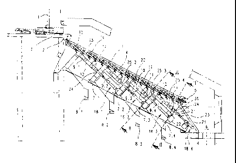
figure 1 shows a longitudinal section through a grate
furnace;
figure 2 shows a section along the line II-II in
figure 1, and
figure 3 shows a part section along the line III-III
in figure 1.
A grate furnace according to figure 1 comprises a
charging hopper 1, a charging device 3 which can move
to and fro over a charging table 2, a grate 4, a
collecting device 5 arranged at the end of the grate

CA 02396294 2002-07-31
_ 7 _
for collecting the ash, and an ash chute 6 into which
the burnt ash falls.
Situated under the grate 4 are four mutually separate
underblast chambers 7.1, 7.2, 7.3 and 7.4. These
underblast chambers each have connections 8.1 to 8.4
for the separate supply of primary air, which is blown
toward the grate 4 from the underside and through the
grate into the fuel lying on the grate, for example
refuse .
The underblast chambers are arranged in a stepped
staggered manner in relation to one another following
the inclined grate 4. Arranged above each underblast
chamber is a carriage 9.1 to 9.4 which, as can be seen
in connection with Figure 3 in particular, is in each
case provided with two roller pairs 10 and 11 which are
guided in guide tracks 12. Arranged on each carriage
are drivers 13 and 14, each of which is in engagement
with a movable grate step 15 and, respectively, 16. The
furnace grate is composed of in each case alternately
movable and stationary grate steps, a stationary grate
step 17 being provided in each case between two movable
grate steps 15 and 16. A carriage 9 is therefore
provided for the motive drive of two movable grate
steps. The guide tracks 12 are aligned parallel to the

CA 02396294 2002-07-31
movement direction of the movable grate steps 15 and
16.
A drive device designated as a whole by reference
number 18, which comprises a working cylinder 19, a
piston (not shown in the drawing) which is movable in
the working cylinder, and a piston rod 20, serves for
displacing each carriage 9 and the grate steps 15 and
16 connected thereto. The working cylinder 19 is
fastened to a transverse beam 22 by means of an
articulation arrangement 21, while the piston rod 20 is
connected via an articulation 23 to a push rod 24 which
extends through a seal 35 of a housing to be described
below.
Each drive device, with the exception of the drive
device 18.4 which serves for the drive of the last two
movable grate steps just before the ash chute, are
[sic] arranged in a housing 25 which is continuous in
the illustrative embodiment and is divided into housing
chambers which are designated by reference numbers 25.2
to 25.4 below. These housing chambers 25, which can be
seen from Figures 2 and 3 in particular, surround the
drive devices 18.1, 18.2 and 18.3 in a protective
manner. The drive arrangement 1$.4 is situated under a
feed hopper 26 for the ash chute 6 and is consequently

CA 02396294 2002-07-31
- 9 -
located outside the grate region, for which reason a
housing chamber is not provided for this drive.
As can be seen from figure 2, the grate furnace
illustrated in the drawing has two grate paths next to
one another, which are designated by reference numbers
4a and 4b. The grate paths concerned are situated
between lateral pressing plates 27 which are loaded by
spring arrangements 28 in order to be capable of
compensating lateral thermal expansion of the grate
paths. The housing chambers 25 for accommodating the
drive devices 18 have thermal insulation 29 and forced
ventilation, the corresponding ducts for the forced
ventilation not being shown in the drawing. Flaps 31
articulated by means of an articulation 3'0 make
possible assembly and maintenance of the drive devices
18.
As can be seen from figures 2 and 3, the housings 25
concerned are of streamlined design and configured and
arranged in such a manner that an essentially constant
flow cross section 32 remains in each case between the
inner wall 33 of an underblast chamber 7 and the outer
wall 34 of the housing 25.

Representative Drawing
A single figure which represents the drawing illustrating the invention.
Administrative Status

2024-08-01:As part of the Next Generation Patents (NGP) transition, the Canadian Patents Database (CPD) now contains a more detailed Event History, which replicates the Event Log of our new back-office solution.

Please note that "Inactive:" events refers to events no longer in use in our new back-office solution.

For a clearer understanding of the status of the application/patent presented on this page, the site Disclaimer , as well as the definitions for Patent , Event History , Maintenance Fee  and Payment History  should be consulted.

Event History

Description Date
Inactive: Expired (new Act pat) 2022-08-02
Inactive: COVID 19 - Deadline extended 2020-07-16
Common Representative Appointed 2019-10-30
Change of Address or Method of Correspondence Request Received 2018-03-28
Grant by Issuance 2006-09-05
Inactive: Cover page published 2006-09-04
Pre-grant 2006-04-24
Inactive: Final fee received 2006-04-24
Inactive: IPC from MCD 2006-03-12
Notice of Allowance is Issued 2006-02-23
Letter Sent 2006-02-23
Notice of Allowance is Issued 2006-02-23
Inactive: Approved for allowance (AFA) 2005-12-22
Amendment Received - Voluntary Amendment 2005-07-26
Inactive: S.30(2) Rules - Examiner requisition 2005-02-02
Application Published (Open to Public Inspection) 2003-02-01
Inactive: Cover page published 2003-01-31
Letter Sent 2002-11-15
Inactive: IPC assigned 2002-10-07
Inactive: First IPC assigned 2002-10-04
Inactive: IPC assigned 2002-10-04
All Requirements for Examination Determined Compliant 2002-09-25
Request for Examination Requirements Determined Compliant 2002-09-25
Request for Examination Received 2002-09-25
Inactive: Filing certificate - No RFE (English) 2002-09-13
Letter Sent 2002-09-13
Application Received - Regular National 2002-09-13

Abandonment History

There is no abandonment history.

Maintenance Fee

The last payment was received on 2006-06-19

Note : If the full payment has not been received on or before the date indicated, a further fee may be required which may be one of the following

  • the reinstatement fee;
  • the late payment fee; or
  • additional fee to reverse deemed expiry.

Patent fees are adjusted on the 1st of January every year. The amounts above are the current amounts if received by December 31 of the current year.
Please refer to the CIPO Patent Fees web page to see all current fee amounts.

Owners on Record

Note: Records showing the ownership history in alphabetical order.

Current Owners on Record
MARTIN GMBH FUR UMWELT-UND ENERGIETECHNIK
Past Owners on Record
JOHANNES JOSEF EDMUND MARTIN
PETER WEBER
WERNER FAMILLER
Past Owners that do not appear in the "Owners on Record" listing will appear in other documentation within the application.
Documents

To view selected files, please enter reCAPTCHA code :


To view images, click a link in the Document Description column. To download the documents, select one or more checkboxes in the first column and then click the "Download Selected in PDF format (Zip Archive)" or the "Download Selected as Single PDF" button.

List of published and non-published patent-specific documents on the CPD .

If you have any difficulty accessing content, you can call the Client Service Centre at 1-866-997-1936 or send them an e-mail at CIPO Client Service Centre.


Document
Description 
Date
(yyyy-mm-dd) 
Number of pages   Size of Image (KB) 
Representative drawing 2002-10-06 1 19
Abstract 2002-07-30 1 20
Description 2002-07-30 9 288
Claims 2002-07-30 3 71
Drawings 2002-07-30 2 67
Claims 2005-07-25 2 55
Description 2005-07-25 9 296
Representative drawing 2006-08-07 1 21
Courtesy - Certificate of registration (related document(s)) 2002-09-12 1 112
Filing Certificate (English) 2002-09-12 1 162
Acknowledgement of Request for Examination 2002-11-14 1 176
Reminder of maintenance fee due 2004-03-31 1 109
Commissioner's Notice - Application Found Allowable 2006-02-22 1 161
Correspondence 2006-04-23 1 39