Note: Descriptions are shown in the official language in which they were submitted.
CA 02396338 2002-07-03
WO 02/37720 PCT/US01/44793
1
AN APPARATUS AND METHOD FOR MULTIPLEXING AND/OR
DEMULTIPLEXING OPTICAL SIGNALS HAVING SUBSTANTIALLY
EQUAL DISPERSION
BACKGROUND OF THE INVENTION
The present invention relates generally to terminal equipment for an optical
communication system. More specifically, the present invention relates to
optical
transmitters multiplexing and optical receivers demultiplexing optical having
substantially equal dispersion.
U.S. Patent No. 5,224,183, entitled "Multiple Wavelength Division
Multiplexing Signal Compensation System and Method Using Same" and issued on
June 29, 1993, discloses a wavelength-division multiplexing (WDM) system. FIG.
1 illustrates a wavelength-division multiplexing system disclosed in U.S.
Patent No.
5,224,183. As FIG. I illustrates, each wavelength has an associated laser
coupled to
a dispersion-compensation fiber, which in turn is coupled to a common
wavelength
division multiplexer. For example, lasers 12, 14 and 16 are coupled to
dispersion-
compensation fibers 18, 20 and 22, respectively, which are coupled to
wavelength
division multiplexer 24. In this example, the wavelength of laser 12 is 1540
nm; the
wavelengtli of laser 14 is 1550 nm; the wavelength of laser 16 is 1560 nm.
Wavelength division multiplexer 24 is coupled to a an additional dispersion-
compensating fiber 26 and transmission fiber 28.
This known system individually compensates the dispersion associated with
each wavelength before the optical signals are multiplexed by the wavelength
division
multiplexer (and after the optical signals are demultiplexed by the wavelength
division
demultiplexer (not shown in FIG.1)). This is performed for each wavelength by
a
separate and unique dispersion-compensation fiber associated with that
wavelength:
dispersion-compensation fiber 12 has a dispersion of -20 ps/nm at its
wavelength
(1540 nm), dispersion-compensation fiber 14 has a dispersion of -200 ps/nm at
its
wavelength (1550 nm), and dispersion-compensation fiber 16 has a dispersion of
-360
ps/nm at its ' wavelength (1550 nm). These dispersion-compensation fibers
CA 02396338 2002-07-03
WO 02/37720 PCT/US01/44793
2
compensate individually for each particular wavelength to produce a unique
residual
dispersion associated with each wavelength. Each wavelength is subsequently
compensated by the dispersion-compensation fiber 26 and transmission fiber 28.
By
eliminating the residual dispersion associated with each wavelength at the
wavelength-
division multiplexer 24, the dispersion of all of the wavelengths at the end
of the
transmission fiber 28 can be controlled to a desired amount, such as for
example,
approximately zero dispersion for approximately all of the wavelengths.
Such a WDM system, however, suffers several shortcomings. First, each
wavelength requires a separate and unique dispersion-compensating fiber
disposed,
for example, between the respective laser and the wavelength-division
multiplexer of
the optical transmitter. Similarly, each wavelength requires a separate and
unique
dispersion-compensation fiber disposed, for example, between the wavelength-
division multiplexer and the respective detector (not shown in FIG. 1). As WDM
systems having more and more information channels are designed, adding more
and
more dispersion-compensation fibers associated with each wavelength make the
WDM system more complex and expensive.
Second, polarization of the optical signals received by the wavelength-
division
multiplexer cannot be maintained due to the unique dispersion-compensation
fibers
required by each wavelength. Consequently, although desirable for the optical
signals
associated each wavelength to have an associated polarization that is
orthogonal to the
adjacent wavelengths, such an arrangement is not possible where the
polarization
cannot be maintained.
SUMMARY
An apparatus for coinmunicating data through information channels each
being associated witli its own wavelength comprises modulators and an optical
multiplexer. Each modulator is associated with its own wavelength. The optical
multiplexer is operationally coupled to the modulators. The optical
multiplexer
receives multiple input optical signals each of which is received from its own
CA 02396338 2002-07-03
WO 02/37720 PCT/US01/44793
3
modulator. Each input optical signal has its own dispersion substantially
equal to a
dispersion of each remaining input optical signals.
BRIEF DESCRIPTION OF THE DRAWINGS
FIG. 1 illustrates a known wavelength-division multiplexing system.
FIG. 2 illustrates an optical system having an optical transmitter, according
to
an embodiment of the present invention.
FIG. 3 illustrates an optical system including a receiver system, according to
an embodiment of the present invention.
FIG. 4 illustrates an optical system including an optical receiver, according
to
another embodiment of the present invention.
DETAILED DESCRIPTION
An apparatus for communicating data through information channels each
being associated with its own wavelength comprises modulators and an optical
multiplexer. Each modulator is associated with its own wavelength. The optical
multiplexer is operationally coupled to the modulators. The optical
multiplexer
receives multiple input optical signals each of which is received from its own
modulator. Each input optical signal has its own dispersion substantially
equal to a
dispersion of each reinaining input optical signals.
Unlike,the known system where each information channel (i.e., each optical
signal associated with a particular wavelength) is individually dispersion
compensated
with a unique amount of dispersion, optical transmitters and optical receivers
of the
present invention (e.g., as disposed within terminal equipment) need not
satisfy such
a requirement. Each such information channel need not be individually
dispersion
compensated where the optical transmitter and/or optical receiver are coupled
to a
transmission fiber having a zero dispersion-slope. In such transmission fiber,
dispersion compensation is performed substantially equally for all of the
information
channels (i.e., for all of the associated wavelengths). Consequently, these
optical
transmitters and optical receivers can multiplex and deinultiplex,
respectively, optical
CA 02396338 2002-07-03
WO 02/37720 PCT/US01/44793
4
signals having substantially equal dispersion. Thus, for example, the optical
transmitters and optical receivers need not include any wavelength-specific
dispersion-
compensating fibers. Of course, this advantageously reduces the coinplexity
and
expense of such optical transmitters and optical receivers.
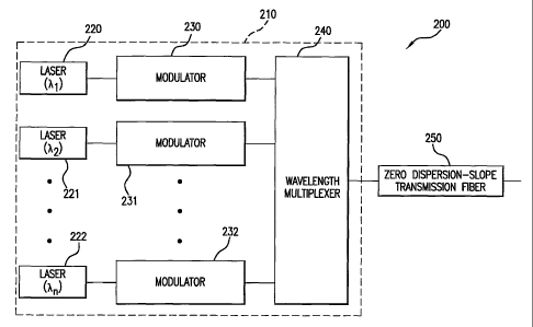
FIG. 2 illustrates an optical system having an optical transmitter, according
to
an embodiment of the present invention. Optical system 200 includes optical
transmitter 210 and zero-dispersion-slope transmission fiber 250. Optical
transmitter
210 includes a series of lasers 220, 221 through 222. Each laser has it own
associated
wavelength, for example, lasers 220, 221, and 222 have the associated
wavelengths
Xi, kz and k,,, respectively, centered around, for example, 1550 nm. Each
laser 220
through 222 is coupled to its own modulator 230 through 232, respectively. For
example, laser 220 is coupled to modulator 230, laser 221 is coupled to
modulator
231, and laser 222 is coupled to modulator 232. Modulators 230 through 232 are
coupled to wavelength multiplexer 240. Transmitter 210 is operationally
coupled to
zero-dispersion-slope transmission fiber 250 via wavelength multiplexer 240.
Transmission fiber 250 has a commutative dispersion-slope substantially equal
to zero. For example, such a transmission fiber can have a zero dispersion-
slope
through an appropriate combination of first fiber-type segments having a
positive
dispersion slope and second fiber-type segments having a negative dispersion
slope.
The first fiber type can have, for example, a dispersion, D1, of 16.9 ps/nm-
km;
a dispersion slope, D1', of 0.06 ps/nm2-km; and an effective area of 75 m2.
Such a
type of optical fiber is commercially available as "single-mode fiber (SMF)".
The
SMF fiber is produced by several fiber manufacturers including Coming and
Lucent.
The relative dispersion slope of the first fiber type equals the ratio of the
first-fiber-
type dispersion slope and dispersion, D'1/D1.
The second fiber type can have, for example, a dispersion, D2, of -17.0 ps/nm-
km; a dispersion slope, DZ', of -0.06 ps/nm2-km; and an effective area of 35
m2.
Such a type of optical fiber has been designated commercially as "lx inverse-
dispersion fiber (lx-IDF)". Another example of an optical fiber having a
negative
CA 02396338 2007-12-05
dispersion slope is the optical fiber designated commercially as "2x-IDF"
which has a
dispersion of -34.0 ps/nm-km and a dispersion slope of -0.12 ps/nm2-km and an
effective area of about 34 m2. Both the Ix-IDF and the 2x-IDF fibers are
produced
by Lucent.
5 The relative dispersion slope of the second fiber type equals the ratio of
the
second-fiber-type dispersion slope and dispersion, D' 2,/DZ. By appropriately
selecting the dispersion and dispersion slope of the first fiber type and of
the second
fiber type, the relative dispersion slope of the first fiber type and of the
second fiber
type can be selected to be approximately equal.
FIG. 3 illustrates an optical system including a receiver system, according to
an embodiment of the present invention. The optical system (including the
receiver
system) shown in FIG. 3 can be used in conjunction with the optical system
(including the transmitter system) shown in FIG. 2 (of course, a single
zero-dispersion-slope transmission fiber can be considered).
Optical system 300 includes optical receiver 310 and zero-dispersion-slope
transmission fiber 350. Optical receiver 310 includes a series of detectors
320
through 322. Each detector 320 through 322 are connected to demodulators 330
through 332, respectively. For example, detector 320 is coupled to demodulator
330,
detector 331 is coupled to demodulator 331 and detector 322 is coupled to
demodulator 332. Demodulators 330 through 332 are coupled to wavelength
demultiplexer 340. Optical receiver 310 is operationally coupled to
zero-dispersion-slope transmission fiber 350 through wavelength demultiplexer
340.
CA 02396338 2002-07-03
WO 02/37720 PCT/US01/44793
6
As the examples shown in FIG. 2 and 3 illustrate, these optical transmitters
and optical receivers can inultiplex and demultiplex, respectively, optical
signals
having substantially equal dispersion. Thus, for example, the optical
transmitters and
optical receivers need not include any wavelength-specific dispersion-
compensating
fibers. Of course, this advantageously reduces the complexity and expense of
such
optical transmitters and optical receivers.
In an alternative of the embodiment of the invention, rather than having
absolutely no dispersion compensating fibers within the optical transmitters
and
receivers, it is possible that dispersion-compensation fibers can be included
where
each of the dispersion-compensation fibers introduce substantially the same
amount
of dispersion.
FIG. 4 illustrates an optical system including an optical receiver, according
to
another embodiment of the present invention. Optical transmitter 410 is
coupled to
zero-dispersion-slope transmission fiber 460. Optical transmitter 410 includes
lasers
420, 421 through 422. Again, each laser has its own associated wavelength. For
example, lasers 420 through 422 can be associated with wavelengths k1, kZ and
a,,,,
respectively. Each of the lasers 420 through 422 are coupled to its own
modulator 430
through 432, respectively. For example, laser 420 is coupled to modulator 430,
laser
421 is coupled to modulator 431, and laser 422 is coupled to modulator 432.
Modulators 430 through 432 are each coupled to its own polarization selector
440
through 442. For example, modulator 430 is coupled to polarization selector
440,
modulator 431 is coupled to polarization selector 441, and modulator 432 is
coupled
to polarization selector 442. Polarization selectors 440 through 442 are
coupled to
wavelength multiplexer 450. Optical transmitter 410 is coupled to zero-
dispersion-
slope transmission fiber 460 via wavelength multiplexer 450.
Polarization selectors 440 through 442 allow the optical signals received from
the modulators 430 through 432, respectively, to be sent to wavelength
multiplexer
450 so that the optical signals each have a specific polarization that is
orthogonal to
the polarization of adjacent information channels (i.e., for the optical
signals having
next lower wavelength and next higher wavelengtll).
CA 02396338 2002-07-03
WO 02/37720 PCT/US01/44793
7
More specifically, polarization selectors 440 through 442 can be configured,
for example, so that the specific polarization selected for a given
information channel
is orthogonal to the polarization for the adjacent information chamlel. Said
another
way, the specific polarization selected for a given wavelength can be, for
example,
orthogonal from the polarization selected for that of the next lower
wavelength and
the next higher wavelength. For example, polarization selector 440 can be
configured
to select a vertical linear polarization; polarization selector 441 which can
be
associated with the next higher wavelength (i.e., adjacent to that of
polarization
selector 440), can be configured to select, for example, horizontal linear
polarization.
The next polarization selector for the next higher wavelength (i.e., adjacent
to that
associated with polarization selector 441) can be configured to select
vertical linear
polarization. Accordingly, the remaining polarization selectors can be
configured to
select ortl7ogonal polarizations in an alternating manner through to
polarization
selector 442.
Polarization selectors 440 tlirough 442 can be any appropriate device which
outputs an optical signal in a particular polarization. For example,
polarization
selectors 440 through 442 can be a polarization beam splitter where only one
of the
two potential polarized light signals are coupled to the wavelength
multiplexer 450.
By selecting alternating orthogonal polarizations for the information channels
(i.e., for the optical signals associated with the range of wavelengths),
better system
performance can be achieved because potential sources of interchamiel cross-
talk,
such as for example, intersymbol interference (ISI) can be reduced. Because
each of
the optical signals (e.g., entering and leaving the wavelength multiplexer and
wavelength demultiplexer) have substantially the same amount of dispersion,
the
polarization selected by the polarization selectors 440 tllrough 442 and
associated wit11
the respective optical signals can be maintained until they are multiplexed by
wavelength multiplexer 450. Furthermore, because the transinission fiber 460
has a
zero dispersion-slope the optical signals at all of the wavelengths are
equally
dispersion compensated. In addition, the relative polarization states of the
channels
set by the polarization selectors 440 through 442 can be maintained until they
are
CA 02396338 2002-07-03
WO 02/37720 PCT/US01/44793
8
demultiplexed by a wavelength demultiplexer within the optical receiver (not
shown
in FIG. 4). Thus, once the optical signals are received at the receiver, the
optical
signals still have substantially the same amount of dispersion and additional
wavelength-specific dispersion coinpensation is not needed.
Said another way, individually varied dispersion for each associated
wavelength is not required within the optical transmitter 410, the
transmission fiber
460 or the optical receiver (not shown in FIG. 4). The relative polarization
states of
the optical signals can be maintained from the optical transmitter 410 to it
associated
optical receiver (are not shown in FIG. 4). Therefore, the benefits expected
from
associating orthogonal polarization with the various information channels (and
their
respective associated wavelengths) can be achieved.
In an alternative of the embodiment of the invention, rather than having
absolutely no dispersion compensating fibers within the optical transmitters
and
receivers, it is possible that dispersion-compensation fibers can be included
where
each of the dispersion-compensation fibers introduce substantially the same
amount
of dispersion. In such a case, because the same amount of dispersion is
introduced
into each optical signal for all the wavelengths, the polarization introduced
by
polarization selectors of the optical transmitter can be maintained through to
the
wavelength multiplexer as well as through to the zero-dispersion-slope
transmission
fiber and the wavelength demultiplexer of the optical receiver.
It should, of course, be understood that while the present invention has been
described in reference to particular configurations, other configurations
should be
apparent to those of ordinary skill in the art. For example, although certain
components are discussed as being coupled or operationally coupled to other
components, other intervening components can be possible, such as optical
fiber
couplers, etc.