Note: Descriptions are shown in the official language in which they were submitted.
CA 02396525 2002-08-01
RAIL ROAD CAR TRUCK WITH ROCKING SIDEFRAME
Field of the Invention
This invention relates to the field of rail road cars, and, more particularly,
to
the field of three piece rail road car trucks for rail road cars.
Background of the Invention
Rail road cars in North America commonly employ double axle swivelling
trucks known as "three piece trucks" to permit them to roll along a set of
rails. The
three piece terminology refers to a truck bolster and pair of first and second
sideframes. In a three piece truck, the truck bolster extends cross-wise
relative to the
sideframes, with the ends of the truck bolster protruding through the
sidefrarne
windows. Forces are transmitted between the truck bolster and the sideframes
by
spring groups mounted in spring seats in the sideframes.
One general purpose of a resilient suspension system may tend to be to reduce
force transmission to the car body, and hence to the lading. This may apply to
very
stiff suspension systems, as suitable for use with coal and grain, as well as
to
relatively soft suspension systems such as may be desirable for more fragile
goods,
such as rolls of paper, automobiles, shipping containers fruit and vegetables,
and
white goods.
One determinant of overall ride quality is the dynamic response to lateral
perturbations. That is, when there is a lateral perturbation at track level,
the rigid steel
wheelsets of the truck may be pushed sideways relative to the car body.
Lateral
perturbations may arise for example from uneven track, or from passing over
switches
or from turnouts and other track geometry perturbations. When the train is
moving at
speed, the time duration of the input pulse due to the perturbation may be
very short.
The suspension system of the truck reacts to the lateral perturbation. It is
generally desirable for the force transmission to be relatively low. High
force
transmissibility, and corresponding high lateral acceleration, may tend not to
be
advantageous for the lading. This is particularly so if the lading includes
relatively
fragile goods. In general, the lateral stiffness of the suspension reflects
the combined
displacement of (a) the sideframe between (i) the pedestal bearing adapter and
(ii) the
bottom spring seat (that is, the sideframes swing laterally as a pendulum with
the
pedestal bearing adapter being the top pivot point for the pendulum); and (b)
the
CA 02396525 2002-08-01
- 2 -
lateral deflection of the springs between (i) the lower spring seat in the
sideframe and
(ii) the upper spring mounting against the underside of the truck bolster, and
(c) the
moment and the associated transverse shear force between the (i) spring seat
in the
sideframe and (ii) the upper spring mounting against the underside of the
truck
bolster.
In a conventional rail road car truck, the lateral stiffness of the spring
groups is
sometimes estimated as being approximately 1/2 of the vertical spring
stiffness. Thus
the choice of vertical spring stiffness may strongly affect the lateral
stiffness of the
suspension. The vertical stiffness of the spring groups may tend to yield a
vertical
deflection at the releasable coupler from the light car (i.e., empty)
condition to the
fully laden condition of about 2 inches. For a conventional grain or coal car
subject to
a 286,000 lbs., gross weight on rail limit, this may imply a dead sprung load
of some
50,000 lbs., and a live sprung load of some 220,000 lbs., yielding a spring
stiffness of
25 ¨ 30,000 lbs./in., per spring group (there being, typically, two groups per
truck,
and two trucks per car). This may yield a lateral spring stiffness of 13 ¨
16,000 lbs./in
per spring group. It should be noted that the numerical values given in this
background discussion are approximations of ranges of values, and are provided
for
the purposes of general order-of-magnitude comparison, rather than as values
of a
specific truck.
The second component of stiffness relates to the lateral deflection of the
sideframe itself. In a conventional truck, the weight of the sprung load can
be
idealized as a point load applied at the center of the bottom spring seat.
That load is
carried by the sideframe to the pedestal seat mounted on the bearing adapter.
The
vertical height difference between these two points may be in the range of
perhaps 12
to 18 inches, depending on wheel size and sideframe geometry. For the general
purposes of this description, for a truck having 36 inch wheels, 15 inches (+/-
) might
be taken as a roughly representative height.
The pedestal seat may typically have a flat surface that bears on an upwardly
crowned surface on the bearing adapter. The crown may typically have a radius
of
curvature of about 60 inches, with the center of curvature lying below the
surface (i.e.,
the surface is concave downward).
When a lateral shear force is imposed on the springs, there is a reaction
force
in the bottom spring seat that will tend to deflect the sideframe, somewhat
like a
pendulum. When the sideframe takes on an angular deflection in one direction,
the
21046116.1
CA 02396525 2002-08-01
- 3 -
line of contact of the flat surface of the pedestal seat with the crowned
surface of the
bearing adapter will tend to move along the arc of the crown in the opposite
direction.
That is, if the bottom spring seat moves outboard, the line of contact will
tend to move
inboard. This motion is resisted by a moment couple due to the sprung weight
of the
car on the bottom spring seat, acting on a moment arm between (a) the line of
action
of gravity at the spring seat and (b) the line of contact of the crown of the
bearing
adapter. For a 286,000 lbs. car the apparent stiffness of the sideframe may be
of the
order of 18,000 ¨ 25,000 lbs./in, measured at the bottom spring seat. That is,
the
lateral stiffness of the sideframe (i.e., the pendulum action by itself) can
be greater
than the (already relatively high) lateral stiffness of the spring group in
shear, and this
apparent stiffness is proportional to the total sprung weight of the car
(including
lading). When taken as being analogous to two springs in series, the overall
equivalent lateral spring stiffness may be of the order of 8,000 lbs./in. to
10,000, per
sideframe. A car designed for lesser weights may have softer apparent
stiffness. This
level of stiffness may not always yield as smooth a ride as may be desired.
There is another component of spring stiffness due to the unequal compression
of the inside and outside portions of the spring group as the bottom spring
seat rotates
relative to the upper spring group mount under the bolster. This stiffness,
which is
additive to (that is, in parallel with) the stiffness of the sideframe, can be
significant,
and may be of the order of 3000 - 3500 lbs./in per spring group, depending on
the
stiffness of the springs and the layout of the group. Other second and third
order
effects are neglected for the purpose of this description. The total lateral
stiffness for
one sideframe, including the spring stiffness, the pendulum stiffness and the
spring
moment stiffness, for a S2HD 110 Ton truck may be about 9200 lbs/inch per side
frame.
It has been observed that it may be preferable to have springs of a given
vertical stiffness to give certain vertical ride characteristics, and a
different
characteristic for lateral perturbations. In particular, a softer lateral
response may be
desired at high speed (greater than about 50 m.p.h) and relatively low
amplitude to
address a truck hunting concern, while a different spring characteristic may
be
desirable to address a low speed (roughly 10 ¨ 25 m.p.h) roll characteristic,
particularly since the overall suspension system may have a roll mode
resonance lying
in the low speed regime.
An alternate type of three piece truck is the "swing motion" truck. One
example of a swing motion truck is shown at page 716 in the 1980 Car and
21046116.1
õ
CA 02396525 2010-06-08
- 4
Locomotive Cyclopedia (1980, Simmons-Boardman, Omaha). This illustration, with
captions removed, is the basis of Figures la, lb and lc, herein, labelled
"Prior Art÷.
Since the truck has both lateral and longitudinal axes of symmetry, the artist
has only
shown half portions of the major components of the truck. The particular
example
illustrated is a swing motion truck produced by National Castings Inc., more
commonly referred to as "NACO". Another example of a NACO Swing Motion truck
is shown at page 726 of the 1997 Car and Locomotive Cyclopedia (1997, Simmons-
Boardroom, Omaha). An earlier swing motion three piece truck is shown and
described in US Patent 3,670,660 of Weber et al., issued June 20, 1972, the
specification of which is incorporated herein by reference.
In a swing motion truck, the sideframe is mounted as a "swing hanger" and
acts much like a pendulum. In contrast to the truck described above, the
bearing
adapter has an upwardly concave rocker bearing surface, having a radius of
curvature
of perhaps 10 inches and a center of curvature lying above the bearing
adapter. A
pedestal rocker seat nests in the upwardly concave surface, and has itself an
upwardly
concave surface that engages the rocker bearing surface. The pedestal rocker
seat has
a radius of curvature of perhaps 5 inches, again with the center of curvature
lying
upwardly of the rocker.
In this instance, the rocker seat is in dynamic rolling contact with the
surface
of the bearing adapter. The upper rocker assembly tends to act more like a
hinge than
the shallow crown of the bearing adapter described above. As such, the
pendulum
may tend to have a softer, perhaps much softer, response than the analogous
conventional sideframe. Depending on the geometry of the rocker, this may
yield a
sideframe resistance to lateral deflection in the order of 1/4 (or less) to
about V2 of what
might otherwise be typical. If combined in series with the spring group
stiffness, it
can be seen that the relative softness of the pendulum may tend to become the
dominant factor. To some extent then, the lateral stiffness of the truck
becomes less
strongly dependent on the chosen vertical stiffness of the spring groups at
least for
small displacements. Furthermore, by providing a rocking lower spring seat,
the
swing motion truck may tend to reduce, or eliminate, the component of lateral
stiffness that may tend to arise because of unequal compression of the inboard
and
outboard members of the spring groups, thus further softening the lateral
response.
In the truck of US Patent 3,670,660 the rocking of the lower spring seat is
limited to a range of about 3 degrees to either side of center, and a transom
extends
between the sideframes, forming a rigid, unsprung, lateral connecting member
21000913.2
CA 02396525 2010-06-08
- 5 -
between the rocker plates of the two sideframes. In this context, "unsprung"
refers to
the transom being mounted to a portion of the truck that is not resiliently
isolated
from the rails by the main spring groups.
When the three degree condition is reached, the rockers "lock-up" against the
side frames, and the dominant lateral displacement characteristic is that of
the main
spring groups in shear, as illustrated and described by Weber. The lateral,
unsprung,
sideframe connecting member, namely the transom, has a stop that engages a
downwardly extending abutment on the bolster to limit lateral travel of the
bolster
relative to the sideframes. This use of a lateral connecting member is shown
and
described in US Patent 3,461,814 of Weber, issued March 7, 1967. As noted in
US
Patent 3,670,660 the use of a spring plank had been known, and the use of an
abutment at the level of the spring plank tended to permit the end of travel
reaction to
the truck bolster to be transmitted from the sideframes at a relatively low
height,
yielding a lower overturning moment on the wheels than if the end-of-travel
force
were transmitted through gibs on the truck bolster from the sideframe columns
at a
relatively greater height. The use of a spring plank in this way was
considered
advantageous.
In Canadian Patent 2,090,031, (issued April 15, 1997 to Weber et al.,) noting
the advent of lighter weight, low deck cars, Weber et al., replaced the
transom with a
lateral rod assembly to provide a rigid, unsprung connection member between
the
platforms of the rockers of the lower spring seats. One type of car in which
relative
lightness and a low main deck has tended to be found is an Autorack car.
For the purposes of rapid estimation of truck lateral stiffness, the following
formula can be used:
ktruck = 2 x [ (ksideframe)-1 + (kspring shear)]i
where
ksideframe = [kpendulum + kspring moment
kspring shear = The lateral spring constant for the spring group in
shear.
kpendulum = The force required to deflect the pendulum per unit
of
deflection, as measured at the center of the bottom spring seat.
kspring moment = The force required to deflect the bottom spring seat per unit
of sideways deflection against the twisting moment caused by
the unequal compression of the inboard and outboard springs.
21000913.2
CA 02396525 2002-08-01
- 6 -
In a pure pendulum, the relationship between weight and deflection is
approximately linear for small angles of deflection, such that, by analogy to
a spring
in which F =k, a lateral constant (for small angles) can be defined as
kpenduium = W /
L, where k is the lateral constant, W is the weight, and L is the pendulum
length.
Further, for the purpose of rapid comparison of the lateral swinging of the
sideframes,
an approximation for an equivalent pendulum length for small angles of
deflection
can be defined as Leg = W kpendulum= In this equation W represents the sprung
weight
borne by that sideframe, typically Vs of the total sprung weight for a
symmetrical car.
For a conventional truck, Leg may be of the order of about 3 or 4 inches. For
a swing
motion truck, Leg may be of the order of about 10 to 15 inches.
It is also possible to define the pendulum lateral stiffness (for small
angles) in
terms of the length of the pendulum, the radius of curvature of the rocker,
and the
design weight carried by the pendulum: according to the formula:
kpendulum = (Flateral/Olateral) = (Wilapendulum)[(Rcurvatureilapendulum) + 1]
where:
kpenduium = the lateral stiffness of the pendulum
Fiaterai = the force per unit of lateral deflection
6Iatera1 = a unit of lateral deflection
W = the weight borne by the pendulum
I-pendulum = the length of the pendulum, being the vertical distance from the
contact surface of the bearing adapter to the bottom spring seat
Rcurvature = the radius of curvature of the rocker surface
Following from this, if the pendulum stiffness is taken in series with the
lateral
spring stiffness, then the resultant overall lateral stiffness can be
obtained. Using this
number in the denominator, and the design weight in the numerator yields a
length,
effectively equivalent to a pendulum length if the entire lateral stiffness
came from an
equivalent pendulum according to I-
-,esultant = W / klateral total
For a conventional truck with a 60 inch radius of curvature rocker, and stiff
suspension, this length, I
¨,esultant may be of the order of 6 ¨ 8 inches, or thereabout.
So that the present invention may better be understood by comparison, in the
prior art illustration of Figures la, lb, and 1 c, a NACO swing motion truck
is
21046116.1
CA 02396525 2002-08-01
- 7 -
identified generally as A20. Inasmuch as the truck is symmetrical about the
truck
center both from side-to-side and lengthwise, the artist has shown only half
of the
bolster, identified as A22, and half of one of the sideframes, identified as
A24.
In the customary manner, sideframe A24 has defined in it a generally
rectangular window A26 that admits one of the ends of the bolster A28. The top
boundary of window A26 is defined by the sideframe arch, or compression member
identified as top chord member A30, and the bottom of window A26 is defined by
a
tension member, identified as bottom chord A32. The fore and aft vertical
sides of
window A26 are defined by sideframe columns A34.
At the swept up ends of sideframe A24 there are sideframe pedestal fittings
A38 which each accommodate an upper rocker identified as a pedestal rocker
seat
A40, that engages the upper surface of a bearing adapter A42. Bearing adapter
A42
itself engages a bearing mounted on one of the axles of the truck adjacent one
of the
wheels. A rocker seat A40 is located in each of the fore and aft pedestals,
the rocker
seats being longitudinally aligned such that the sideframe can swing
transversely
relative to the rolling direction of the truck A20 generally in what is
referred to as a
"swing hanger" arrangement.
The bottom chord of the sideframe includes pockets A44 in which a pair of
fore and aft lower rocker bearing seats A46 are mounted. The lower rocker seat
A48
has a pair of rounded, tapered ends or trunnions A50 that sit in the lower
rocker
bearings A48, and a medial platform A52. An array of four corner bosses A54
extend
upwardly from platform A52.
An unsprung, lateral, rigid connecting member in the nature of a spring plank,
or transom A60 extends cross-wise between the sideframes in a spaced apart,
underslung, relationship below truck bolster A22. Transom A60 has an end
portion
that has an array of four apertures A62 that pick up on bosses A54. A
grouping, or set
of springs A64 seats on the end of the transom, the corner springs of the set
locating
above bosses A54.
The spring group, or set A64, is captured between the distal end of bolster
A22
and the end portion of transom A60. Spring set A64 is placed under compression
by
the weight of the rail car body and lading that bears upon bolster A22 from
above. In
consequence of this loading, the end portion of transom A60, and hence the
spring set,
are carried by platform A54. The reaction force in the springs has a load path
that is
21046116.1
CA 02396525 2002-08-01
- 8 -
carried through the bottom rocker A70 (made up of trunnions A50 and lower
rocker
bearings A48) and into the sideframe A22 more generally.
Friction damping is provided by damping wedges A72 that seat in mating
bolster pockets A74. Bolster pockets A74 have inclined damper seats A76. The
vertical sliding faces of the friction damper wedges then ride up an down on
friction
wear plates A80 mounted to the inwardly facing surfaces of the sideframe
columns.
The "swing motion" truck gets its name from the swinging motion of the
sideframe on the upper rockers when a lateral track perturbation is imposed on
the
wheels. The reaction of the sideframes is to swing, rather like pendula, on
the upper
rockers. When this occurs, the transom and the truck bolster tend to shift
sideways,
with the bottom spring seat platform rotating on the lower rocker.
The upper rockers are inserts, typically of a hardened material, whose
rocking,
or engaging, surface A80 has a radius of curvature of about 5 inches, with the
center
of curvature (when assembled) lying above the upper rockers (i.e., the surface
is
upwardly concave).
As noted above, one of the features of a swing motion truck is that while it
may be quite stiff vertically, and while it may be resistant to parallelogram
deformation because of the unsprung lateral connection member, it may at the
same
time tend to be laterally relatively soft.
Summary of the Invention
In the view of the present inventor, the lower rocker and the transom of the
prior art swing motion truck may tend to add complexity to the truck. In the
view of
the present inventor, it would be advantageous to retain the upper rocker
geometry of
a swing motion truck, while eliminating either the transom, or the bottom
rocker, or
preferably both. In consequence, in an aspect of the invention there is a
swing motion
rail road car truck that is free of unsprung cross bracing. In another aspect
of the
invention there is a swing motion rail road car truck that is free of (a) a
transom; (b) a
frame brace; and (c) unsprung lateral bracing rods. In another aspect of the
invention
there is a swing motion rail road car truck that is free of a bottom rocker.
In still another aspect of the invention there is a sideframe assembly for a
swing motion rail road car truck. The sideframe assembly has a frame member.
The
21046116.1
CA 02396525 2002-08-01
- 9 -
frame member has a pair of first and second longitudinally spaced apart
bearing
pedestals. The sideframe has a pair of first and second rockers. The first
rocker is
mounted in a swing hanger arrangement to the first bearing pedestal. The
second
bearing rocker is mounted in a swing hanger arrangement to the second bearing
pedestal. The first and second bearing rockers are aligned on a common axis. A
spring seat is rigidly mounted in the sideframe, whereby, when the sideframe
rocks on
the rockers, the spring seat swings rigidly with the sideframe.
In a further aspect of the invention there is a swing motion rail road car
truck.
The swing motion rail road car truck has a truck bolster having a first end
and a
second end. The truck has a pair of first and second sideframes. Each of the
sideframes has a sideframe window defined therein for accommodating an end of
a
truck bolster, and has a spring seat for receiving a spring set. The spring
seat is
rigidly oriented with respect to the sideframe window. The truck has a first
spring set
and a second spring set. The first spring set is mounted in the spring seat of
the first
sideframe, and the second spring set is mounted in the spring seat of the
second
sideframe. The truck bolster is mounted cross-wise relative to the sideframes.
The
first end of the truck bolster is supported by the first spring set. The
second end of the
truck bolster is supported by the second spring set. The first and second
sideframes
each have rocker mounts for engaging first and second axles. The rocker mounts
are
mounted in a swing hanger arrangement to permit cross-wise swinging motion of
the
sideframes.
In yet another aspect of the invention there is a sideframe assembly for a
swing Motion rail road car truck. The sideframe assembly has a frame member.
The
frame member has a pair of first and second longitudinally spaced apart
bearing
pedestals and a pair of first and second rockers. The first rocker is mounted
in a
swing hanger arrangement to the first bearing pedestal. The second bearing
rocker is
mounted in a swing hanger arrangement to the second bearing pedestal. The
first and
second bearing rockers are aligned on a common axis. A spring seat is rigidly
mounted in the sideframe, whereby, when the sideframe rocks on the rockers the
spring seat swings rigidly with the sideframe.
In another aspect of the invention there is a swing motion rail road car
truck.
The truck has a truck bolster having a first end and a second end. The truck
has a pair
of first and second sideframes for accommodating an end of a truck bolster,
and has a
spring seat for receiving a spring set. The spring seat is rigidly mounted
with respect
21046116.1
CA 02396525 2002-08-01
- 10 -
to the sideframe. The truck has a first spring group and a second spring
group. The
first spring group is mounted in the spring seat of the first sideframe. The
second
spring group is mounted in the spring seat of the second sideframe. The truck
bolster
is mounted transversely relative to the sideframes. The first end of the truck
bolster is
supported by the first spring group. The second end of the truck bolster is
supported
by the second spring group. The first and second sideframes each have rocker
mounts
for engaging first and second axles of a wheelset. The rocker mounts are
mounted in
a swing hanger arrangement to permit cross-wise swinging motion of the
sideframes
relative to the wheelset.
In an additional feature of that aspect of the invention, the truck is free of
underslung lateral cross-bracing. In another additional feature, the truck is
free of a
transom. In still another additional feature, a set of biased members operable
to
resist parallelogram deformation of the truck is mounted to act between each
end of
the truck bolster and the sideframe associated therewith. One of the sets of
biased
members includes first and second biased members. The first biased member is
mounted to act at a laterally inboard location relative to the second biased
member.
In yet another additional feature, each of the sets of biased members includes
third
and fourth biased members. The third biased member is mounted transversely
inboard of the fourth biased member. In a further additional feature, the
biased
members are friction dampers.
In another additional feature, a set of friction dampers is mounted to act
between each end of the truck bolster and the sideframe associated therewith.
One of
the sets of friction dampers includes first and second friction dampers. The
first
friction damper is mounted to act at a laterally inboard location relative to
the second
friction damper. In yet another additional feature, each of the sets of
friction dampers
includes third and fourth friction dampers. The third friction damper is
mounted
transversely inboard of the fourth friction damper. In still another
additional feature,
the friction dampers are individually biased by springs of the spring groups.
In still yet another additional feature, each of the side frames has an
equivalent
pendulum length Leg in the range of 6 to 15 inches. In a further additional
feature,
each of the spring groups has a vertical spring rate constant of less than
15,000
Lbs./in.
In another aspect of the invention there is a swing motion truck having a pair
of first and second side frames and a truck bolster mounted transversely
relative to the
21046116.1
CA 02396525 2002-08-01
- 11 -
sideframes. The truck bolster has a first end associated with the first side
frame and a
second end associated with the second sideframe. A first set of friction
dampers is
mounted to act between the first end of the truck bolster and the first
sideframe. A
second set of friction dampers is mounted to act between the second end of the
truck
bolster and the second sideframe. The first set of friction dampers includes
at least
four individually sprung friction dampers.
In an additional feature of that aspect of the invention, the friction dampers
are
mounted in a four corner arrangement. In another additional feature, the
friction
dampers include a first inboard friction damper, a second inboard friction
damper, a
first outboard friction damper and a second outboard friction damper. The
first and
second inboard friction dampers are mounted transversely inboard relative to
the first
and second outboard friction dampers.
In yet another additional feature, the truck is free of unsprung lateral
bracing
between the sideframes. In still another additional feature, the truck is free
of a
transom. In still yet another additional feature, each of the sideframes has a
rigid
spring seat, and respective groups of springs are mounted therein between the
spring
seat and a respective end of the truck bolster. In still another additional
feature, each
of the friction dampers are sprung on springs of the spring groups. In a
further
additional feature, each of the sideframes has a rocking spring seat. In still
a further
additional feature, each of the sideframes has an equivalent pendulum length,
Leg, in
the range of 6 to 15 inches.
In yet a further additional feature, a first spring group is mounted between
the
first end of the truck bolster and the first side frame. A second spring group
is
mounted between the second end of the truck bolster and the second side frame.
Each
of the first and second spring groups has a vertical spring rate constant k
that is less
than 15,000 Lbs./in per group.
In another aspect of the invention there is a swing motion rail road car
truck.
The truck has a truck bolster having a first end and a second end and a pair
of first and
second sideframes. Each of the sideframes accommodates an end of the truck
bolster,
and has a spring seat for receiving a spring group. The truck has a first
spring group
and a second spring group. The first spring group is mounted in the spring
seat of the
first sideframe. The second spring group is mounted in the spring seat of the
second
sideframe. The truck bolster is mounted cross-wise relative to the sideframes.
The
first end of the truck bolster is supported by the first spring group. The
second end of
21046116.1
CA 02396525 2002-08-01
- 12 -
the truck bolster is supported by the second spring group. The first and
second
sideframes each have swing hanger rocker mounts for engaging first and second
axles. The rocker mounts are operable to permit cross-wise swinging motion of
the
sideframes. The truck is free of lateral cross-bracing between the sideframes.
In an
additional feature of that aspect of the invention, the spring seats are
rigidly mounted
to the sideframes.
In another additional feature, a set of biased members, operable to resist
parallelogram deformation of the truck, is mounted to act between each end of
the
truck bolster and the sideframe associated therewith. One of the sets of
biased
members includes first and second biased members. The first biased member is
mounted to act at a laterally inboard location relative to the second biased
member. In
still another additional feature, each of the sets of biased members includes
third and
fourth biased members. The third biased member is mounted transversely inboard
of
the fourth biased member. In yet another additional feature, the biased
members are
friction dampers.
In still yet another additional feature, a set of friction dampers is mounted
to
act between each end of the truck bolster and the sideframe associated
therewith. One
of the sets of friction dampers includes first and second friction dampers.
The first
friction damper is mounted to act at a laterally inboard location relative to
the second
friction damper. In another additional feature, each of the sets of friction
dampers
includes third and fourth friction dampers. The third friction damper is
mounted
transversely inboard of the fourth friction damper. In a further additional
feature, the
friction dampers are individually biased by springs of the spring groups. In
still a
further additional feature, each of the side frames has an equivalent pendulum
length
Leg in the range of 6 to 15 inches. In yet a further additional feature, each
of the
spring groups has a vertical spring rate constant of less than 15,000 Lbs./in.
In still yet a further additional feature, a first set of friction dampers is
mounted to act between the first end of the truck bolster and the first
sideframe. A
second set of friction dampers is mounted to act between the second end of the
truck
bolster and the second sideframe. The first set of friction dampers includes
at least
four individually sprung friction dampers. In another additional feature, the
friction
dampers are mounted in a four corner arrangement. In yet another additional
feature,
the friction dampers include a first inboard friction damper, a second inboard
friction
damper, a first outboard friction damper and a second outboard friction
damper. The
first and second inboard friction dampers are mounted transversely inboard
relative to
21046116.1
CA 02396525 2002-08-01
- 13 -
the first and second outboard friction dampers.
In still yet another additional feature, each of the sideframes has a rigid
spring
seat, and respective groups of springs are mounted therein between the spring
seat and
a respective end of the truck bolster. In a further additional feature, each
of the
friction dampers are sprung on springs of the spring groups. In still a
further
additional feature, each of the sideframes has a rocking spring seat. In yet a
further
additional feature, each of the sideframes has an equivalent pendulum length,
Leg, in
the range of 6 to 15 inches. In still yet a further additional feature, each
of the first
and second spring groups has a vertical spring rate constant k that is less
than 15,000
Lbs./in per group.
Brief Description of The Illustrations
The principles of the invention may better be understood with reference to the
accompanying figures provided by way of illustration of an exemplary
embodiment,
or embodiments, incorporating those principles, and in which:
Figure la shows a prior art exploded partial view illustration of a swing
motion truck based on the illustration shown at page 716 in the 1980
Car and Locomotive Cyclopedia;
Figure lb shows a cross-sectional detail of an upper rocker assembly of the
truck of Figure la;
Figure lc shows a cross-sectional detail of a lower rocker assembly of the
truck of Figure la;
Figure 2a shows a swing motion truck as shown in Figure la, but lacking a
transom;
Figure 2b shows a sectional detail of an upper rocker assembly of the truck of
Figure 2a;
Figure 2c shows a cross-sectional detail of a bottom spring seat of the truck
of
Figure 2a;
Figure 3a shows a swing motion truck having an upper rocker as in the swing
motion truck of Figure la, but having a rigid spring seat, and being
free of a transom;
Figure 3b shows a cross-sectional detail of the upper rocker assembly of the
truck of Figure 3a;
Figure 4 shows a swing motion truck similar to that of Figure 3a, but having
doubled bolster pockets and wedges;
21046116.1
CA 02396525 2002-08-01
- 14 -
Figure 5a shows an isometric view of an assembled swing motion truck
similar to that of Figure 3a, but having a different spring and damper
arrangement;
Figure 5b shows a top view of the truck of Figure 5a showing a 2 x 4 spring
arrangement;
Figure Sc shows the damper arrangement of the truck of Figure 5a;
Figure 5d shows a side view of the truck of Figure 5a; and
Figure 5e shows a view similar to Figure 5b, but with a 3 x 5 spring
arrangement.
DETAILED DESCRIPTION OF THE INVENTION
The description that follows, and the embodiments described therein, are
provided by way of illustration of an example, or examples, of particular
embodiments of the principles of the present invention. These examples are
provided
for the purposes of explanation, and not of limitation, of those principles
and of the
invention. In the description, like parts are marked throughout the
specification and
the drawings with the same respective reference numerals. The drawings are not
necessarily to scale and in some instances proportions may have been
exaggerated in
order more clearly to depict certain features of the invention.
In terms of general orientation and directional nomenclature, for each of the
rail road car trucks described herein, the longitudinal direction is defined
as being
coincident with the rolling direction of the rail road car, or rail road car
unit, when
located on tangent (that is, straight) track. In the case of a rail road car
having a
center sill, the longitudinal direction is parallel to the center sill, and
parallel to the
side sills, if any. Unless otherwise noted, vertical, or upward and downward,
are
terms that use top of rail, TOR, as a datum. The term lateral, or laterally
outboard,
refers to a distance or orientation relative to the longitudinal centerline of
the railroad
car, or car unit. The term "longitudinally inboard", or "longitudinally
outboard" is a
distance taken relative to a mid-span lateral section of the car, or car unit.
Pitching
motion is angular motion of a railcar unit about a horizontal axis
perpendicular to the
longitudinal direction. Yawing is angular motion about a vertical axis. Roll
is
angular motion about the longitudinal axis.
This description relates to rail car trucks. Several AAR standard truck sizes
are listed at page 711 in the 1997 Car & Locomotive Cyclopedia. As indicated,
for a
single unit rail car having two trucks, a "40 Ton" truck rating corresponds to
a
21046116.1
CA 02396525 2010-06-08
- 15 -
maximum gross car weight on rail of 142,000 lbs. Similarly, "50 Ton"
corresponds to
177,000 lbs, "70 Ton" corresponds to 220,000 lbs, "100 Ton" corresponds to
263,000
lbs, and "125 Ton" corresponds to 315,000 lbs. In each case the load limit per
truck is
then half the maximum gross car weight on rail. A "110 Ton" truck is a term
sometimes used for a truck having a maximum weight on rail of 286,000 lbs.
This application refers to friction dampers, and multiple friction damper
systems. There are several types of damper arrangement as shown at pages 715 -
716
of the 1997 Car and Locomotive Encyclopedia, those pages being incorporated
herein
by reference. Double damper arrangements are shown and described in my co-
pending US Patent application, filed contemporaneously herewith and entitled
"Rail
Road Freight Car With Damped Suspension". Each of the arrangements of dampers
shown at pp. 715 to 716 of the 1997 Car and Locomotive Encyclopedia can be
modified according to the principles of my aforesaid co-pending application
for "Rail
Road Freight Car With Damped Suspension" to employ a four cornered, double
damper arrangement of inner and outer dampers.
In the example of Figure 2a and 2b, a truck embodying an aspect of the
present invention is indicated as 10. Truck 10 differs from truck A20 of
Figure la
insofar as it is free of a rigid, unsprung lateral connecting member in the
nature of
unsprung cross-bracing such as a frame brace of crossed-diagonal rods, lateral
rods, or
a transom (such as transom A60) running between the rocker plates of the
bottom
spring seats of the opposed sideframes. Further, truck 10 employs gibs 12 to
define
limits to the lateral range of travel of the truck bolster 14 relative to the
sideframe 16.
In other respects, including the sideframe geometry and upper and lower rocker
assemblies, truck 10 is intended to have generally similar features to truck
A20,
although it may differ in size, pendulum length, spring stiffness, wheelbase,
window
width and window height, and damping arrangement. The determination of these
values and dimensions may depend on the service conditions under which the
truck is
to operate.
As with other trucks described herein, it will be understood that since truck
10
(and trucks 20, 120, and 220, described below) are symmetrical about both
their
longitudinal and transverse axes, the truck is shown in partial section. In
each case,
where reference is made to a sideframe, it will be understood that the truck
has first
and second sideframes, first and second spring groups, and so on.
21000913.2
CA 02396525 2002-08-01
- 16 -
In Figures 3a and 3b, for example, a truck embodying an aspect of the present
invention is identified generally as 20. Inasmuch as truck 20 is symmetrical
about the
truck center both from side-to-side and lengthwise, the bolster, identified as
22, and
the sideframes, identified as 24 are shown in part. Truck 20 differs from
truck A20 of
the prior art, described above, in that truck 20 has a rigid spring seat
rather than a
lower rocker as in truck A20, as described below, and is free of a rigid,
unsprung
lateral connection member such as an underslung transom A60, a frame brace, or
laterally extending rods.
Sideframe 24 has a generally rectangular window 26 that accommodates one
of the ends 28 of the bolster 22. The upper boundary of window 26 is defined
by the
sideframe arch, or compression member identified as top chord member 30, and
the
bottom of window 26 is defined by a tension member identified as bottom chord
32.
The fore and aft vertical sides of window 26 are defined by sideframe columns
34.
The ends of the tension member sweep up to meet the compression member.
At each of the swept-up ends of sideframe 24 there are sideframe pedestal
fittings 38.
Each fitting 38 accommodates an upper rocker identified as a pedestal rocker
seat 40.
Pedestal rocker seat 40 engages the upper surface of a bearing adapter 42.
Bearing
adapter 42 engages a bearing mounted on one of the axles of the truck adjacent
one of
the wheels. A rocker seat 40 is located in each of the fore and aft pedestal
fittings 38,
the rocker seats 40 being longitudinally aligned such that the sideframe can
swing
transversely relative to the rolling direction of the truck in a "swing
hanger"
arrangement.
Bearing adapter 42 has a hollowed out recess 43 in its upper surface that
defines a bearing surface 43 for receiving rocker seat 40. Bearing surface 43
is
formed on a radius of curvature RI. The radius of curvature R1 is preferably
in the
range of less than 25 inches, and is preferably in the range of 8 to 12
inches, and most
preferably about 10 inches with the center of curvature lying upwardly of the
rocker
seat. The lower face of rocker seat 40 is also formed on a circular arc,
having a radius
of curvature R2 that is less than the radius of curvature R1 of recess 43. R2
is
preferably in the range of 1/4 to % as large as R1, and is preferably in the
range of 3 ¨
10 inches, and most preferably 5 inches when R1 is 10 inches, i.e., R2 is one
half of
R. Given the relatively small angular displacement of the rocking motion of R2
relative to R1 (typically less than +/- 10 degrees) the relationship is one of
rolling
contact, rather than sliding contact.
21046116.1
CA 02396525 2002-08-01
- 17 -
The bottom chord or tension member of sideframe 24 has a basket plate, or
lower spring seat 44 rigidly mounted to bottom chord 32, such that it has a
rigid
orientation relative to window 26, and to sideframe 24 in general. That is, in
contrast
to the lower rocker platform of the prior art swing motion truck A20 of Figure
la, as
described above, spring seat 44 is not mounted on a rocker, and does not rock
relative
to sideframe 24. Although spring seat 44 retains an array of bosses 46 for
engaging
the corner elements 54, namely springs 54 and 55 (inboard), 56 and 57
(outboard) of a
spring set 48, there is no transom mounted between the bottom of the springs
and seat
44. Seat 44 has a peripheral lip 52 for discouraging the escape of the bottom
ends the
of springs.
The spring group, or spring set 48, is captured between the distal end 28 of
bolster 22 and spring seat 44, being placed under compression by the weight of
the
rail car body and lading that bears upon bolster 22 from above.
Friction damping is provided by damping wedges 62 that seat in mating
bolster pockets 64 that have inclined damper seats 66. The vertical sliding
faces 70 of
the friction damper wedges 62 then ride up and down on friction wear plates 72
mounted to the inwardly facing surfaces of sideframe columns 34. Angled faces
74 of
wedges 62 ride against the angled face of seat 66. Bolster 22 has inboard and
outboard gibbs 76, 78 respectively, that bound the lateral motion of bolster
22 relative
to sideframe columns 34. This motion allowance may advantageously be in the
range
of +/- 1 1/8 to 1 3/4 inches, and is most preferably in the range of 1 3/16 to
1 9/16
inches, and can be set, for example, at 1 1/2 inches or 1 1/4 inches of
lateral travel to
either side of a neutral, or centered, position when the sideframe is
undeflected.
As in the prior art swing motion truck A20, a spring group of 8 springs in a
3:2:3 arrangement is used. Other configurations of spring groups could be
used, such
as these described below.
In the embodiment of Figure 4, a truck 120 is substantially similar to truck
20,
but differs insofar as truck 120 has a bolster 122 having double bolster
pockets 124
126 on each face of the bolster at the outboard end. Bolster pockets 124, 126
accommodate a pair of first and second, laterally inboard and laterally
outboard
friction damper wedges 128, 129 and 130, 131, respectively. Wedges 128, 129
each
sit over a first, inboard corner spring 132, 133, and wedges 130, 131 each sit
over a
second, outboard corner spring 134, 135. In this four corner arrangement, each
damper is individually sprung by one or another of the springs in the spring
group.
21046116.1
CA 02396525 2002-08-01
- 18 -
The static compression of the springs under the weight of the car body and
lading
tends to act as a spring loading to bias the damper to act along the slope of
the bolster
pocket to force the friction surface against the sideframe. As such, the
dampers co-
operate in acting as biased members working between the bolster and the side
frames
to resist parallelogram, or lozenging, deformation of the side frame relative
to the
truck bolster. A middle end spring 136 bears on the underside of a land 138
located
intermediate bolster pockets 124 and 126. The top ends of the central row of
springs,
140, seat under the main central portion 142 of the end of bolster 122.
The lower ends of the springs of the entire spring group, identified generally
as 144, seat in the lower spring seat 146. Lower spring seat 146 has the
layout of a
tray with an upturned rectangular peripheral lip. Lower spring seat 146 is
rigidly
mounted to the lower chord 148 of sideframe 122. In this case, spring group
144 has
a 3 rows x 3 columns layout, rather than the 3:2:3 arrangement of truck 20. A
3 x 5
layout as shown in Figure 5e could be used, as could other alternate spring
group
layouts. Truck 120 is free of any rigid, unsprung lateral sideframe connection
members such as transom A60.
It will be noted that bearing plate 150 mounted to vertical sideframe columns
152 is significantly wider than the corresponding bearing plate 72 of truck 20
of
Figure 2a. This additional width corresponds to the additional overall damper
span
width measured fully across the damper pairs, plus lateral travel as noted
above,
typically allowing 1 1/2 (+/-) inches of lateral travel of the bolster
relative to the
sideframe to either side of the undeflected central position. That is, rather
than having
the width of one coil, plus allowance for travel, plate 152 has the width of
three coils,
plus allowance to accommodate 1 (+/-) inches of travel to either side. Plate
152 is
significantly wider than the through thickness of the sideframes more
generally, as
measured, for example, at the pedestals.
Damper wedges 128 and 130 sit over 44 % (+/-) of the spring group i.e., 4/9 of
a 3 rows x 3 columns group as shown in Figure 4, whereas wedges 70 only sat
over
2/8 of the 3:2:3 group in Figure 3a. For the same proportion of vertical
damping,
wedges 128 and 130 may tend to have a larger included angle (i.e., between the
wedge hypotenuse and the vertical face for engaging the friction wear plates
on the
sideframe columns 34. For example, if the included angle of friction wedges 72
is
about 35 degrees, then, assuming a similar overall spring group stiffness, and
single
coils, the corresponding angle of wedges 128 and 130 could advantageously be
in the
range of 50 ¨ 65 degrees, or more preferably about 55 degrees. In a 3 x 5
group such
21046116.1
CA 02396525 2002-08-01
- 19 -
as group 270 of truck 280 of Figure 5e, for coils of equal stiffness, the
wedge angle
may tend to be in the 35 to 40 degree range. The specific angle will be a
function of
the specific spring stiffnesses and spring combinations actually employed.
The use of spaced apart pairs of dampers 128, 130 may tend to give a larger
moment arm, as indicated by dimension "2M", for resisting parallelogram
deformation of truck 120 more generally as compared to trucks 20 or A20.
Parallelogram deformation may tend to occur, for example, during the "truck
hunting"
phenomenon that has a tendency to occur in higher speed operation.
Placement of doubled dampers in this way may tend to yield a greater
restorative "squaring" force to return the truck to a square orientation than
for a single
damper alone, as in truck 20. That is, in parallelogram deformation, or
lozenging, the
differential compression of one diagonal pair of springs (e.g., inboard spring
132 and
outboard spring 135 may be more pronouncedly compressed) relative to the other
diagonal pair of springs (e.g., inboard spring 133 and outboard spring 134 may
be less
pronouncedly compressed than springs 132 and 135) tends to yield a restorative
moment couple acting on the sideframe wear plates. This moment couple tends to
rotate the sideframe in a direction to square the truck, (that is, in a
position in which
the bolster is perpendicular, or "square", to the sideframes) and thus may
tend to
discourage the lozenging or parallelogramming, noted by Weber.
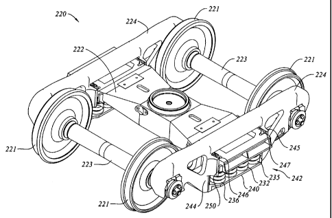
Another embodiment of multiple damper truck 220 is shown in Figures 5a, 5b,
5c and 5d. Truck 220 has a wheel set of four wheels 221 and two axles 223.
Truck
220 is substantially similar to truck 120, but differs insofar as truck 220
has a bolster
222 having single bolster pockets 225, 226 on opposites sides of the outboard
end
portion of the bolster, each being of enlarged width, such as double the width
of the
single pockets shown in Figure 3a, to accommodate a pair of first and second,
inboard
and outboard friction damper wedges 228, 230, (or 229, 231, opposite side) in
side-
by-side independently displaceable sliding relationship relative not only to
the seat of
the pocket, but also with respect to each other. In this instance the spring
group,
indicated as 232, has a 2 rows x 4 columns layout, as seen most clearly in
Figure 5b.
Wedges 228, 230 each sit over a first corner spring 234, 236 and wedges 229,
231
each sit over a second corner spring 233, 235. The central 2 rows x 2 columns
of the
springs bear on the underside of a land 238 located in the main central
portion of the
end of bolster 222 longitudinally intermediate bolster pockets 225 and 227.
21046116.1
CA 02396525 2002-08-01
- 20 -
For the purposes of this description the swivelling, 4 wheel, 2 axle truck 220
has first and second sidefrarnes 224 that can be taken as having the same
upper rocker
assembly as truck 120, and has a rigidly mounted lower spring seat 240, like
spring
seat 144, but having a shape to suit the 2 rows x 4 columns spring layout
rather than
the 3 x 3 layout of truck 120. It may also be noted that sideframe window 242
has
greater width between sideframe columns 244, 245 than window 126 between
columns 128 to accommodate the longer spring group footprint, and bolster 222
similarly has a wider end to sit over the spring group.
In this example, damper wedges 228, 230 and 229, 232 sit over 50 % of the
spring group i.e., 4/8 namely springs 234, 236, 233, 235. For the same
proportion of
vertical damping as in truck 20, wedges 128 and 130 may tend to have a larger
included angle, possibly about 60 degrees, although angles in the range of 45
to 70
degrees could be chosen depending on spring combinations and spring
stiffnesses.
Once again, in a warping condition, the somewhat wider damping region (the
width of
two full coils plus lateral travel of 1 Y2" (+/-)) of sideframe column wear
plates 246,
247 lying between inboard and outboard gibbs 248, 249, 250, 251 relative to
truck 20
(a damper width of one coil with travel), sprung on individual springs
(inboard and
outboard in truck 220, as opposed to a single central coil in truck 20), may
tend to
generate a moment couple to give a restoring force working on a moment arm.
This
restoring force may tend to urge the sideframe back to a square orientation
relative to
the bolster, with diagonally opposite pairs of springs working as described
above. In
this instance, the springs each work on a moment arm distance corresponding to
half
of the distance between the centers of the 2 rows of coils, rather than half
the 3 coil
distance shown in Figure 4.
One way to encourage an increase in the hunting threshold is to employ a
truck having a longer wheelbase, or one whose length is proportionately great
relative
to its width. For example, at present two axle truck wheelbases may generally
range
from about 5' ¨ 3" to 6' ¨ 0". However, the standard North American track
gauge is
4' ¨ 8 1/2", giving a wheelbase to track width ratio possibly as small as
1.12. At 6' ¨
0" the ratio is roughly 1.27. It would be preferable to employ a wheelbase
having a
longer aspect ratio relative to the track gauge.
In the case of truck 220, the size of the spring group yields an opening
between the vertical columns of sideframe of roughly 33 inches. This is
relatively
large compared to existing spring groups, being more than 25 % greater in
width. In
an alternate 3 x 5 spring group arrangement, the opening between the sideframe
21046116.1
CA 02396525 2002-08-01
- 21 -
columns is more than 27 1/2 inches wide. Truck 220 also has a greater
wheelbase
length, indicated as WB. WB is advantageously greater than 73 inches, or,
taken as a
ratio to the track gauge width, and is also advantageously greater than 1.30
times the
track gauge width. It is preferably greater than 80 inches, or more than 1.4
times the
gauge width, and in one embodiment is greater than 1.5 times the track gauge
width,
being as great, or greater than, about 86 inches.
It will be understood that the features of the trucks of Figures 2a, 2b, 3a,
3b,
4, 5a, 5b, 5c and 5d are provided by way of illustration, and that the
features of the
various trucks can be combined in many different permutations and
combinations.
That is, a 2 x 4 spring group could also be used with a single wedge damper
per side.
Although a single wedge damper per side arrangement is shown in Figures 2a and
3a,
a double damper arrangement, as shown in Figures 4 and 5a is nonetheless
preferred
as a double damper arrangement may tend to provide enhanced squaring of the
truck
and resistance to hunting. A 3 x 3 or 3 x 5, or other arrangement spring set
may be
used in place of either a 3:2:3 or 2 x 4 spring set, with a corresponding
adjustment in
spring seat plate size and layout. Similarly, the trucks can use a wide
sideframe
window, and corresponding extra long wheel base, or a smaller window. Further,
each of the trucks could employ a rocking bottom spring seat, as in Figure 2b,
or a
fixed bottom spring seat, as in Figure 3a, 4 or 5a.
When a lateral perturbation is passed to the wheels by the rails, the rigid
axles
will tend to cause both sideframes to deflect in the same direction. The
reaction of the
sideframes is to swing, rather like pendula, on the upper rockers. The
pendulum and
the twisted springs will tend to urge the sideframes back to their initial
position. The
tendency to oscillate harmonically due to the track perturbation will tend to
be
damped out be the friction of the dampers on the wear plates.
As before, the upper rocker seats are inserts, typically of a hardened
material,
whose rocking, or engaging surface 80 has a radius of curvature of about five
inches,
with the center of curvature (when assembled) lying above the upper rockers
(i.e., the
surface is upwardly concave).
In each of the trucks shown and described herein, for a fully laden car type,
the lateral stiffness of the sideframe acting as a pendulum is less than the
lateral
stiffness of the spring group in shear. In one embodiment, the vertical
stiffness of the
spring group is less than 12,000 Lbs./in, with a horizontal shear stiffness of
less than
6000 Lbs./in. The pendulum has a vertical length measured (when undeflected)
from
21046116.1
CA 02396525 2002-08-01
- 22 -
the rolling contact interface at the upper rocker seat to the bottom spring
seat of
between 12 and 20 inches, preferably between 14 and 18 inches. The equivalent
length Leg, may be in the range of 8 to 20 inches, depending on truck size and
rocker
geometry, and is preferably in the range of 11 to 15 inches, and is most
preferably
between about 7 and 9 inches for 28 inch wheels (70 ton "special"), between
about
8 1/2 and 10 inches for 33 inch wheels (70 ton), 9 1/2 and 12 inches for 36
inch wheels
(100 or 110 ton), and 11 and 13 1/2 inches for 38 inch wheels (125 ton).
Although
truck 120 or 220 may be a 70 ton special, a 70 ton, 100 ton, 110 ton, or 125
ton truck,
it is preferred that truck 120 or 220 be a truck size having 33 inch diameter,
or even
more preferably 36 or 38 inch diameter wheels.
In the trucks described herein according to the present invention,
',resultant, as
defined above, is greater than 10 inches, is advantageously in the range of 15
to 25
inches, and is preferably between 18 and 22 inches, and most preferably close
to
about 20 inches. In one particular embodiment it is about 19.6 inches, and in
another
particular embodiment it is about 19.8 inches.
In the trucks described herein, for their fully laden design condition which
may be determined either according to the AAR limit for 70, 100, 110 or 125
ton
trucks, or, where a lower intended lading is chosen, then in proportion to the
vertical
sprung load yielding 2 inches of vertical spring deflection in the spring
groups, the
equivalent lateral stiffness of the sideframe, being the ratio of force to
lateral
deflection measured at the bottom spring seat, is less than the horizontal
shear
stiffness of the springs. The equivalent lateral stiffness of the sideframe
ksideframe is
less than 6000 Lbs./in. and preferably between about 3500 and 5500 Lbs./in.,
and
more preferably in the range of 3700 ¨ 4100 Lbs./in. By way of an example, in
one
embodiment a 2 x 4 spring group has 8 inch diameter springs having a total
vertical
stiffness of 9600 Lbs./ in. per spring group and a corresponding lateral shear
stiffness
ksprmg shear of 4800 lbs./in. The sideframe has a rigidly mounted lower spring
seat. It is
used in a truck with 36 inch wheels. In another embodiment, a 3 x 5 group of 5
1/2
inch diameter springs is used, also having a vertical stiffness of about 9600
lbs./in. in
a truck with 36 inch wheels. It is intended that the vertical spring stiffness
per spring
group be in the range of less than 30,000 lbs./in., that it advantageously be
in the
range of less than 20,000 lbs./in and that it preferably be in the range of
4,000 to
12000 lbs./in, and most preferably be about 6000 to 10,000 lbs./in. The
twisting of
the springs has a stiffness in the range of 750 to 1200 lbs./in. and a
vertical shear
stiffness in the range of 3500 to 5500 lbs./in. with an overall sideframe
stiffness in the
range of 2000 to 3500 lbs./in.
21046116.1
CA 02396525 2002-08-01
- 23 -
In the embodiments of trucks in which there is a fixed bottom spring seat, the
truck may have a portion of stiffness, attributable to unequal compression of
the
springs equivalent to 600 to 1200 Lbs./in. of lateral deflection, when the
lateral
deflection is measured at the bottom of the spring seat on the sideframe.
Preferably,
this value is less than 1000 Lbs./in., and most preferably is less than 900
Lbs./in. The
portion of restoring force attributable to unequal compression of the springs
will tend
to be greater for a light car as opposed to a fully laden car, i.e., a car
laden in such a
manner that the truck is approaching its nominal load limit, as set out in the
1997 Car
and Locomotive Cyclopedia at page 711.
The double damper arrangements shown above can also be varied to include
any of the four types of damper installation indicated at page 715 in the 1997
Car and
Locomotive Cyclopedia, whose information is incorporated herein by reference,
with
appropriate structural changes for doubled dampers, with each damper being
sprung
on an individual spring. That is, while inclined surface bolster pockets and
inclined
wedges seated on the main springs have been shown and described, the friction
blocks
could be in a horizontal, spring biased installation in a pocket in the
bolster itself, and
seated on independent springs rather than the main springs. Alternatively, it
is
possible to mount friction wedges in the sideframes, in either an upward
orientation or
a downward orientation.
The embodiments of trucks shown and described herein may vary in their
suitability for different types of service. Truck performance can vary
significantly based
on the loading expected, the wheelbase, spring stiffnesses, spring layout,
pendulum
geometry, damper layout and damper geometry.
Various embodiments of the invention have now been described in detail. Since
changes in and or additions to the above-described best mode may be made
without
departing from the nature, spirit or scope of the invention, the invention is
not to be
limited to those details but only by the appended claims.
21046116.1