Note: Descriptions are shown in the official language in which they were submitted.
n
CA 02396723 2002-06-17 '''
' ' WO 01148723 ~~ PC"T/HIt00101489
SYSTEM AND METHOD FOR WIRELESS AUTOMATIC METER
READING
Technical Field
The present invention relates to a system and method for wireless
automatic meter reading which can wirelessly and remotely read integrated
amounts
of consumed electric power, water, gas and the like.
Bac around Art
Generally. metermen must personally read integrating meters such as
electric power meters, gas meters, water meters, etc. to charge users rates
for power
consumption, gas consumption, water consumption, etc. Namely. a meterman has
to
check a numerical value of a given integrating meter with the naked eye.
record the
checked value by hand, subtract a numerical value of the last month from the
recorded value and issue a user a bill statement based on the resulting
numerical
value and an integrated amount-to-rate table.
This meter reading process has a disadvantage in that it requires a large
amount of manpower, leading to many ;.xpenses. Also. metermen may erroneously
record numerical values of integrating meters, nobody may be present in
visited
houses. and persons in visited houses may refuse to permit the reading of
integrating
meters. Furthermore, meter reading centers require a large amount of manpower.
leading to many expenses. to process numerical data recorded by meterm;,n
using
computers.
In particular, for power consumption, the amount of load power varies
every moment and reserve power must be used to meet a demanded amount of
power when the maximum load power is applied. Notably, to increase reserve
2 ~ power by 1 % necessitates a national enormous investment. In this regard.
a
1
in
CA 02396723 2002-06-17
WO 01148723 PCT/KR00101489
charge-hy-time system is required to fix a high power rate in the maximum load
power time zone and a low power rate in the minimum load power time zone. for
example, the night time, in turn resulting in a need for the development of
remote '
meter readins units.
S In order to meet this requirement. a large number of remote meter reading
t:nits have beer developed. These meter reading units may be. for example. a
direct
meter reading unit and an automatic meter reading (AMR) unit. The direct meter
reading unit comprises a plurality of sensors instead of a conventional wheel
structure on which a numerical value is recorded. The sensors are used to
record a
i0 read numerical value. The AMR unit comprises sensor means including analog
and
digital circuits for converting physical and electrical amounts varying every
moment
into electrical pulses. The sensor means has a variety of sensors. such ss a
photosensor, magnetometric sensor, hall sensor, etc.. which are provided on a
rotating member of an integrating meter, such as a rotating disc or rotating
drum.
and the body of the meter. Tnis AVIR unit is adapted to continuou~iy integrate
numerical values and automatically transmit the integrated data upon receiving
a
meter reading request.
In order to efficiently and economically perform the remote meter readin;
operation. it is necessary to provide synthetic meter reading means capable of
2 ~ synthetically reading all types of integrating meters including water
meters, gas
meters, hot water meters and the like as well as electric power meters.
However.
enormous development expenses and a lengthy period of time are required in
constructing or modifying the same remote meter reading unit to install it in
meters
of different types. different capacities, different specifications and
different systems.
2 S Further, external factors such as a flash of lighting, power surge. etc.
may
adversely affect the reliability and stability of meters. For example. such
factors
may damage circuits of meters. For this reason. meters must be verified for
2
.~ . ._ .. .~ ,r"",.~"~;;"
t r,=::,~
~: » . .,,, ,, , .
CA 02396723 2002-06-17
' ' WO 01148723 PC'TlI~t00/01489
reliability and stability. However. a great cost and a large amount of time
are
usually required in performing such a verification.
Moreover, integrating meters may be demonstratively installed for the
testing of the remote meter reading operation. However. water meters and gas
meters themselves are high in price and furthermore higher in installation
cost.
resulting in a considerable financial burden ~:or their replacement with new
ones. It
is also impossible for conventional remote meter reading units to perform the
remote meter reading operation for a lengthy period of time using batteries.
Furthermore, when a remote meter reading function fails. a manual meter
Q reading operation must be performed and no misreading of read values must
occur
during the reading operation. For the purpose of overcoming these problems and
the
above problem with the replacement installation, a remote meter reading module
comprising a sensor attached to an existing meter is disclosed in Korean
Patent
Publication No. 199.x-48 r9. However, this meter reading module is
disadvantageous
_ in that the body of the meter must be modified for installation of the
module therein.
resulting in reductions in reliability and stability and an increase in cost.
On the other hand, various approaches have been proposed for the
transmission and reception of data between automatic meter reading terminals
and
meter reading cemers. In particular, a radio frequency (RF) system has been
2 Q developed to solve an installation cost and management cost of a wired
line, which
is the most remarkable disadvantage of a wired system. However. in this RF
system, a meter continuously consumes power because it updates an integrated
value every moment. For this reason, the meter must comprise a separate power
source or battery. For a gas or water meter depending on a battery, a meterman
has
2 ~ to visit periodically (for example, every three to six months) for
replacement of the
battery due to the continuous power consumption.
3
v m
.:, ..;r<.,.... 'r
CA 02396723 2002-06-17
WO 01/48723 PC'T/HIt00/01489
Disclosure of the Invention
Therefore, the present invention has been made in view of the above
problems, and it is an object of the present invention to provide a system and
method for wireless automatic meter reading which can wirelessly and remotely
reaj integrated amounts of consumed electric power, water, gas and the lire.
It is another object of the present invention to provide a system and method
for wireless automatic meter reading which is capable of being simply attached
or
mounted to the meters to perform a wireless remote reading operation.
It is a further object of the present invention to provide a system and
.0 method for wireless automatic meter reading which is mountable to all types
of
integrating meters including electric power meters, water meters, gas meters
and the
Nice to wirelessly and remotely read integrated amounts from the integrating
meters.
It is a further object of the present invention to provide a system and
method for wireless automatic meter reading wherein the integrating meters
need
not be verified for reliability and stability.
It is a further object of the present invention to provide a system and
method for wireless automatic meter reading which can perform a wireless
remote
reading operation without modifying the bodies of the integrating meters.
It is a further object of the present invention to provide a system and
method for wireless automatic meter reading which can minimize power
consumption of a battery to perform a wireless remote reading operation for a
maximized battery lifetime (for example, two to five years).
It is a further object of the present invention to provide a system and
method for wireless automatic meter reading which can employ a self induced .
S current source, a solar cell or an organic electrolyte solar cell as a
battery. resulting
in no necessity for replacing the battery.
9
?'. ~.'~Y~: 4i1 .
... .e~Yi'~ . .. . .:w ,;,;...
'~ w k. _r . -,
- CA 02396723 2002-06-17
WO 01/48723 PCTlIQt00/01489
It is a further object of the present invention to provide a system and
method for wireless automatic meter reading which can temporarily store
integrated
values by time zones and then transmit the stored values wirelesslv.
It is a further object of the present invention to provide a svstern and
method for wireless automatic meter reading wherein numerals of the
integrating
meters are not hidden so that a manual reading operation can be performed when
a
wireless remote reading function fails.
It is another object of the present invention to provide a s~~stem and method
for wireless automatic meter reading which can unify integrated amounts of a
group
of integrating meters into one data unit and transmit the integrated data unit
over
one communication line, thereby significantly reducing an occupancy duration
and
communication amount of the communication line.
It is yet another object of the present invention to provide a system and
method for wireless automatic meter reading which can transmit and receive
data
... r~ecessan~ to a wireless remote reading operation over power line
communication,
thereby performing the wireless remote reading operation irrespective of the
positions of the integrating meters.
In accordance with one aspect of the present invention, the above and other
objects can be accomplished by the provision of a system for wirelessly and
2 ~ remotely reading an integrating meter, comprising an image sensor module
installed
in a predetermined portion of the integrating meter for scanning a display of
the
meter, the image sensor module including an image sensor for picking up an
image
of a numeral displayed on the display and converting the picked-up image into
an
electrical signal; a dynamic random access memory for storing data of the
numeral
image picked-up by the image sensor; a digital signal processor for performing
a
preprocessing operation for the numeral image data stored in the dynamic
random
access memory to extract only components neeessaw to numeral
5
~i ~i
. : '-.: : ,..,..~. , ._ ,..~ , .~ '-:- , -;.~:..: t ~.:r :,; ._
CA 02396723 2002-06-17 .~ '
1
' ' WO 01/48723 PCT/KR00/01489
recognition therefrom: a main processor unit for comparing data extracted by
the
digital signal processor with a recognition library stored in an electrically
erasable
and programmable read only memory, generating a numeric code corresponding to
.
the numeral image in accordance with the compared result and storing the
generated
.. numeric code in a flash read only memory; a radio frequency module for
transmitting numeric code data stored in the flash read only memory and/or
code
data of a numeral currently displayed on the display to a meter reading center
for a
predetermined period of time and receiving a command from the meter readins
center: a synchronous time controller for performing a sleep mode operation in
a
.. normal state and. only when the current time is in accord with a timing
code of the
command received by the radio frequency module, supplying power from a power
supply to an optical character reader module and the radio frequency module to
minimize power consumption; and the meter reading center adapted for receiving
and processing the numeric code data transmitted by the radio frequency module
and transmitting the timing code to the radio frequency module for execution
of a
wireless remote reading operation.
Preferably, the image sensor module may be mounted at a predetermined
portion outside a casing of the integrating meter while being spaced apart
from the
casing at a certain distance. As an alternative, the image sensor module may
be
c 0 mounted at a predetermined portion outside a transparent window of the
integrating
meter. In this case, the image sensor may be a transparent plate image sensor
composed of a plastic polymer transistor, such that a meterman can view the
interior
of the integrating meter so as to perform a manual meter reading operation.
Alternatively, the image sensor module may be installed in a bottom wall
of the integrating meter at a predetermined portion above or under the display
and a 1
transparent body may be installed between the display and the image sensor
module
to refract the image of the numeral displayed on the display and transmit the
6
NI ~ I
'.: ... ;f Q~~,. ..,
CA 02396723 2002-06 17
' ' WO O1/487Z3 PCTI~00/01489
refracted image to the image sensor module.
Preferably, the transparent body may have a cylindrical shape, a right
triangular shape with its edges rounded, a right-angled triangular shape and a
prism
shape.
.. In another embodiment, the image sensor module and the transparent body
may be formed integrally with each other and in close proximity to each other.
In
this case, the image sensor may be a transparent plate image sensor composed
of a
plastic polymer transistor, such that a meterman can view the interior of the
integrating meter so as to perform a manual meter reading operation.
In a further embodiment, the image sensor module may be attached on an
internal or external surface of a casing or transparent window of the
integrating
meter or mounted to the casing or transparent window of the integrating meter
via a
hole. :alternatively, the image sensor module may be attached on an internal
surface of a protective casing or container of the integrating meter.
In yet another embodiment, the image sensor module may be attached on
an e~cternal surface of a protective casing or container of the integrating
meter.
mounted via a hole to the protective casing or container of the integrating
meter or
attached on an external surface of a casing or transparent window of the
integrating
meter such that it moves telescopically toward the display.
Preferably. the radio frequency module may include a master radio
frequency module and a plurality of slave radio frequency modules within a
given
area, the master radio frequency module and the slave radio frequency modules
transmitting and receiving data therebetween on the basis of their
identification
codes, the master radio frequency module transmitting and receivinU data
tolfrorn
2 5 the meter reading center on the basis of its identification code. thereby
significantly
reducing an occupancy duration and communication amount of a communication
line.
7
Iil
~" :'-i ~ : .. .". :;1v3'~
CA 02396723 2002-06-17 - ~.
WO 01/487?3 PC'T/KROOI01489
Preferably, the radio frequency module may be a radio pico cell module or
bluetooth module.
On the other hand. a two-way data transmission/reception terminal. such as
an interactive pager or a two-way messenger, may be provided to perform the
transmission and reception of data between the radio frequency module and the
meter reading center. :~s an alternative. a d 3ra network-based cellemetrv
system.
such as a personal communication service system, a code division multiple
access
system, a time division multiple access system or a global system for mobile
communication, may be provided to perform the transmission and reception of
data
i ~ between the radio frequency module and the meter reading center.
Preferably, the optical character reader module and the image sensor
:nodule may be integrated into a one-chip unit, thereby making it easy to
install and
manage the system.
Preferably, power line communication means may be provided to transmit
_ .. and receive data between the image sensor module and the radio frequency
module
aye. a power line when the integrating meter is installed in a communication
dead
zone. More preferably, the power line communication line may include a pair of
induction coils connected to the power line or a pair of capacitors connected
to the
power line.
? 0 Preferably, the power supply may include a replaceable battery. a
transparent solar cell, an organic electrolyte solar cell or an induced
current source.
In accordance with another aspect of the present invention. there is
provided a method for wirelessiy and remotely reading an integrating meter.
comprising the steps of a) picking up an image of a numeral displayed on a
display
2 5 of the integrating meter and converting the picked-up image into an
electrical ,
signal; b) storing data of the picked-up numeral image in a dynamic random
access
memory; c) performing a preprocessing operation for the numeral image data
8
-- CA 02396723 2002-06-17
WO O1/487Z3 PCT/I~t00/01489
stored in the dynamic random access memory to extract only components
necessary
to numeral recognition therefrom; d) comparing the extracted data with a
recognition library stored in an electrically erasable and programmable read
only
memory, generating a numeric code corresponding to the numeral image data in
accordance with the compared result and storing the generated numeric code in
a
flash read only memory; e) transmitting numeric code data stored in the 'lash
read
only memory and/or code data of a numeral currently displayed on the display
to a
meter reading center via a radio frequency module for a predetermined period
of
time: and f) receiving and processing the numeric code data transmitted via
the
radio frequency module.
Preferably, the numeric code data may be temporarily stored in the flash
r~~d only memory prior to its transmission to the meter reading center.
The meter reading center may transmit a command to the integrating meter.
the command including a command code for instructing the integrating meter to
_.. pe:form an image pickup operation and an identification code for
designating the
iraegrati.ng meter. On the other hand, the numeric code data transmitted to
the meter
reading center via the radio frequency module may include numeric data
regarding
an integrated amount and an identification code indicative of the integrating
meter.
Brief Description o,~~e ]~rayinos_
The above and other objects, features and other advantages of the present
invention will be more clearly understood from the following detailed
description
taken in conjunction with the accompanying drawings, in which:
Fig. 1 is a block diagram showing the construction of a system and method
for wireless automatic meter reading in accordance with a preferred embodiment
of
2 5 the present invention;
Figs. ?a to 2e are perspective views of various ernbadiments of an
9
ui
- , CA 02396723 2002-06-17 - ~ ~ ~~~i' %-_~r. ,",
' WO 01/48723 PCT/1Qt00101489
image sensor module in Fig. 1:
Figs. 3a to 3d are sectional views of various embodiments of a transparent
body in Fig. 2d,
Figs. :~a to 4c are views showing various embodiments of a power supply
in accordance with the present invention;
Fig. ~ is a schematic view. illustrating a communication relation between an
integrating meter installed in a dead zone and a radio frequency module:
Figs. 6a and 6b are schematic circuit diagrams illustrating different
embodiments of a power communication system in Fig. ~;
1 ;, Fi~,. 7 is a block diagram showing the construction of a system and
method
for wireless automatic meter reading in accordance with an alternative
embodiment
of the present invention; and
Fig. 8 is a flowchart illustrating the operation of the wireless remote
reading system for the integrating meter in accordance with the present
invention.
Best Vtode for Carn~ins~1 ti the Invention
The present invention provides a wireless remote reading system- for an
integrating meter comprising an image preprocessor. a processor for reading
identification and data codes. a small-sized optical character reader module
including a one-chip memory for the processing of mass data, and a time
controller
having a normal sleep function for minimizing power consumption.
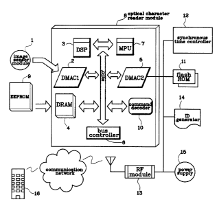
With reference to Fig. 1, there is shown in block form the construction of a
wireless remote reading system for an integrating meter in accordance with a
preferred embodiment of the present invention. As shown in this drawing. the
wireless remote reading system comprises an image sensor module 1 fixedly
2 S installed in a predetermined portion of the top wall or bottom wall of the
integrating
meter for sensing an image of a numeral on a display of the meter and
n
- t '»:-' ~ .. ; . . ~, . . :.~. .
CA 02396723 2002-06-17 -
WO 01148723 PCT/Iflt00101489
converting the sensed image into an electrical signal.
The image sensor module 1 includes a solid-state image sensor for picking
up an image and converting the picked-up image into an electrical signal The
solid-state image sensor may preferably be a charge coupled device (CCD) image
.. sensor, a bucket brigade device (BBD) image sensor, a plasma coupled device
(PCDj image sensor. a complementary metal-oxide semiconducror (CMOS) image
sensor or a transparent plate image sensor composed of a plastic polymer
transistor.
Tae :make sensor module 1 is installed in tre top wall or bottom wall of the
integrating meter at such a position that a meterman can personally read a
numeral
_.. on the display with the naked eye. :~ltern. ativeiy. the image sensor
module I may be
made of a transparent material such that a meterman can personally read the
numeral on the display with the naked eve irrespective of the installed
position of
the image sensor module 1.
The image sensor module can be installed in integrating meters, such as
.., electric power miters. water meters, gas meters and the like. in various
ways, as
shown in Figs. 2a to 2e. For example, the image sensor module may be attached
on
the internal surface or external surface of a cover or casing of an
integrating meter
or mounted to the meter cover or casing via a hole. Alternatively, the image
sensor
module may be installed in a predetermined portion of the integrating meter
while
being neither attached nor mounted on the cover or casing of the meter but
spaced
apart therefrom at a certain distance.
Fia. 2a shows the structure of an image sensor module '?0 mounted at a
predetermined portion outside a transparent casing 22 of an electric power
meter
while being spaced apart from the casing 22 at a certain distance, and Fig. 2b
show's
G J the structure of an image sensor module 30 mounted at a predetermined
portion
outside a transparent window 32 of a water or gas meter while being spaced
apart
from the window 32 at a certain distance. A fixing member 21 ar 31 is attached
11
CA 02396723 2002-06-17
WO 01/48723 PCTl1Qt00/01489
to the transparent casing 22 of the electric power meter or the transparent
window
32 of the water or gas meter, and the image sensor module 20 or 30 is mounted
to
the top of the fixing member 21 or 31 in such a manner that it can pick up an
image '
of a numeral on a display 23 or 33 of the power meter or the water or gas
meter.
., As shown in Fig. 2c, an image sensor module 40. which includes a
transparent plate image sensor composed of a plastic polymer transistor, may
be .
attached directly to a transparent casing 42 or transparent window of an
integrating
meter to pick up an image of a numeral on a display :~3 of the meter. This
arrangement is made to prevent the image sensor module 40 from being
externally
grajected. Further, the image sensor module 40 is transparent not to hide the
display
~3. thereby making it easy to perform a manual meter reading operation when
the
wireless remote meter reading function fails. As an alternative, the image
sensor
module may be installed in the integrating meter at such a position that it
does not
hide the display. In this case, similarly, the manual meter reading operation
can be
... performed easily at any time when the wireless remote meter reading
function fails.
Fig. ?d shows the structure of an image sensor module ~0 installed in the
bottom wall of an integrating meter at a predetermined portion inside a casing
or
transparent window of the meter for picking up a refracted numeral image.
transparent body 51 with a desired shape is attached on the bottom wall of the
%0 integrating meter at a predetermined portion under a display ~3. and the
image
sensor module ~0 is installed in the bottom wall of the integrating meter at a
predetermined portion spaced apart from the transparent body ~ 1 at a certain
distance to pick up a numeral image projected on the body 51. In other words.
the
image sensor module of the present invention can pick up a numeral ima~~e on
the
2 S display ~3 even within the casing of the integrating meter.
The transparent body ~ l, which refracts a numeral image on the display 53.
may have a variety of shapes, for example, a cylindrical shape as shown
12
w,
:~~=;~x
CA 02396723 2002-06-17
WO 01148723 PCTIKR00I01489
in Fig. 3a. a right triangular shape with its edges rounded as shown in Fig.
3b. a
typical right-angled triangular shape as shown in Fig. 3c and a prism shape as
shown in Fig. 3d. For the right-angled triangular transparent body, an angle
of
inclination of the sloping side relative to the base must be set in
consideration of a
refraction angle.
The transparent body 61 having the prism shape as shown in Fig. 3d is
applicable to a transparent plate image sensor module 60 as shown in Fig. ?e.
In
this case. the transparent body 61 and the transparent plate image sensor
module 60
may be implemented in a single unit, as shown in Fig. 2e, because the image
sensor
module 60 is able to pick up a numeral image projected on the body 6l in close
proximity to the body 61. This implementation is applicable to an integrating
meter
wherein a display 63 and a casing 62 are spaced apart from each ocher at a
narrow
interval, in that it can minimize the distance between the transparent body 61
and
the transparent plate image sensor module b0.
1 ~ Referring again to Fig. l, a first data memory access controller (DMAC)
is adapted to store digital image data corresponding to an electrical image
signal
from the image sensor module 1 in a dynamic random access memory (DRAM) 4
and transfer the stored digital image data to a digital signal processor (DSP)
3 for
image preprocessing. The first DMAC 2 is further adapted to store the results
2 0 processed by the DSP 3 in the DRAM 4. Namely. the first DMAC 2 controls
the
input and output of data to/from the DRAM 4 via a bus. A second DMAC
functions to control the input and output of data between a radio frequency
I,RF)
module 13 and a main processor unit (MPU) 7.
'The DSP 3 is adapted to perform a preprocessing operation for the digital
2 S image data transferred by the first DMAC 2 so that the transferred digital
image
data can be recognixed as a numeral. Namely, the DSP 3 removes noise
components
from the received digital image data and rapidly and effectively calculates
the
13
CA 02396723 2002-06-17 PCT
IPEA/~,R I 9. 0 3. 2002
resulting digital irzi~ge data to extract a shape, line segments and
coordinate values
necessary to numeral recognition therefrom. Then, the DSP 3 stores the
calculated
results in the DRAM 40 under the control of the first DMAC 2. A bus controller
6 is
connected to the bus to control an internal data transfer rate.
An optical character reader module 8, which recognizes numerals from a
numeral image signal inputted through the image sensor module 1 and generates
corresponding numeral codes, includes the DSP 3, the MPU 7 and the large-scale
DRAM 4.
The DRAM 4 is adapted to store and output the digital image data
corresponding to the electrical image signal from the image sensor module 1.
The
DRAM 4 is further adapted to store the result data from the DSP 3, load a
recognition algorithm coded in an electrically erasable and programmable read
only
memory (EEPROM) 9 therein and output the stored result data and the loaded
recognition algorithm to the MPU 7 for recognition calculation of the digital
image
data. Namely, the DRAM 4 supports the image sensor module 1, the DSP 3 and
the MPU 7 in common.
Software with a high recognition rate is programmed in a desktop computer
and then transferred to the EEPROM 9 in a hardware coding manner. The
EEPROM 9 is an external nonvolatile memory acting to transfer a program stored
2 0 therein to the DRAM 4 in response to a request from the MPU 7.
A flash ROM 11 acts to store an integrated numeral, recognized and
encoded by the MPU 7, under the control of the second DMAC 5. The flash ROM
11 further stores information, transmitted from a meter reading center 16 and
decoded by a command decoder 10, and transfers the stored information to a
2 5 synchronous time controller 12. Namely, the flash ROM 11 stores an
identification
(ID) code, meter reading time information and an integrated numeric
code and transfers them to the RF module (for example, a radio pico cell
14
~~ ~a~~~(~o~, v~~
CA 02396723 2002-06-17 PcTIhR
IPEA/,s 19. 0 3. 2002
module or bluetooti~ module) r3 in response to a transmission request.
The MPU 7 is adapted to perform a calculation operation for the results
processed by the DSP 3 and a recognition library, loaded from the EEPROM 9 to
the DRAM 4, and encode the resulting recognition numeral. Further, the MPU 7
checks a synchronous time of the synchronous time controller 12, encodes a
meter
reading time in accordance with the checked result and stores the resulting
meter
reading time code in the flash ROM 11 via the command decoder 10.
The synchronous time controller 12 is adapted to control the time of supply
of power from a power supply 15 to associated components, or the RF module 13
and optical character reader module 8, in response to a meter reading time
code
transmitted from the meter reading center 16, decoded by the command decoder
10.
In other words, the synchronous time controller 12 is normally in a sleep mode
to
supply no power from the power supply 15, and proceeds to an awake mode upon
receiving a meter reading time code transmitted from the meter reading center
16, to
supply power from the power supply 15 to the optical character reader module 8
only for a time period (for example, one to two minutes) designated by the
received
meter reading time code. Also in the awake mode, the synchronous time
controller
12 supplies the power from the power supply 15 to the RF module 13 only for a
time period (for example, one to two hours) designated by a received command
2 0 code. Further, for accurate transmission and reception synchronization,
the
controller 12 sets the standard time to time information, transmitted from the
meter
reading center 16 to the RF module 13, and interacts with the MPU 7 to
generate a
meter read time code and transmit it to the meter reading center 16.
The command decoder 10 is adapted to decode codes from the MPU 7, RF
2 5 module 13 and synchronous time controller 12 and store the decoded results
in the
flash ROM 11. An identification (ID) generator 14 is adapted to generate an
ID code (including an address and ID number) of the associated integrating
~y~iE.l~a~ED SNEET(Aj~;T.34>
CA 02396723 2002-06-17
L 111111 . .
meter, thereby enalilirig the mefer reading center 16 to accurately transmit
numeric
data wirelessly to a desired integrating meter.
Although in the embodiment of the present invention the command decoder
is described as being separately provided, it is desirable that all the
functions of
5 the command decoder 10 are implemented by the MPU 7.
The power supply 15 includes a rechargeable battery for supplying a drive
voltage to the optical character reader module 8 and RF module 13. The
rechargeable battery may preferably be a hydrogen battery or thin-film lithium
battery. The synchronous time controller 12 automatically monitors the level
of
10 output power from the battery and the amount of charges stored on the
battery. In
the present invention, power is consumed only for the operation of the optical
character reader module 8 for image recognition and the communication with the
meter reading center 16. In this regard, the power supply 15 need not always
remain
"ON" and its life can thus be maintained for two to five years or more.
The power supply 15 includes a rechargeable and replaceable battery, as
stated previously. Alternatively, the power supply 15 may include a
transparent
solar cell as shown in Fig. 4a, an organic electrolyte solar cell as shown in
Fig. 4b or
an induced current source as shown in Fig. 4c. That is, a transparent solar
cell 73
may be attached on a casing 72 of an integrating meter 71, as shown in Fig.
4a, or
2 0 an organic electrolyte solar cell 74 may be attached on a predetermined
portion of
the body of the integrating meter 71, as shown in Fig. 4b. In either case, the
solar
cell is suitable for an outdoor integrating meter in that it requires heat
from the sun.
Current may be induced in an induction coil 77 facing a coil 76 extending from
a
power line 75, as shown in Fig. 4c. This induced current is useable in spaces
2 5 receiving no sunshine, such as underground, as well as outdoors.
On the other hand, an integrating meter 91 may be installed in
a communication dead zone such as underground, as shown in Fig. 5. In this
16
~PriE~~IDED SNEET(A~T. ~~)
CA 02396723 2002-06-17 pCT/KR
Tnr~ %T~~ 1 . 0 .~ ~
l1 LIr% tui 9 3
case, the integrating meter 91 can be connected to an outdoor RF module 97
over
power line communication. The RF module 97 can transfer data between the
integrating meter 91 and a meter reading center. To this end, a transmission
module
93 must be provided in the integrating meter 91 including an image sensor
module
92, and a reception module 96 must be provided in the RF module 97. The RF
module 97 is coupled with a receptacle 95 of a power line 94 in such a way
that it
can readily be decoupled therefrom with no separate work. Figs. 6a and 6b
illustrate
different embodiments of a power communication system for placing data
regarding
an integrated amount on a power line and extracting the data from the power
line. In
the power communication system of Fig. 6a, a pair of induction coils 78 and 81
connected to a power line 79 are installed respectively in an integrating
meter and
an 1RF module. Alternatively, in the power communication system of Fig. 6b,
input
and output terminals of an RF module and integrating meter are connected to a
power line 80 respectively via capacitors 82 and 83. These two systems can
selectively be used according to the conditions of an integrating meter and RF
module.
In either system, a filter is provided to filter the integrated amount data
transmitted over the power line communication, so as to prevent unnecessary
components from being transmitted.
2 0 On the other hand, a plurality of integrating meters 90-98 may be grouped
into a single unit in a given area, as shown in Fig. 7. In this case, image
sensor
modules and RF modules 100-108 paired therewith are installed respectively in
the
integrating meters in such a manner that one RF module 100 is a master and the
other 1tF modules 101-108 are slaves. With this construction, the master RF
module
can unify numeric data regarding integrated amounts of the respective
integrating
meters and transmit the unified data to a meter reading center over one
communication line.
17
R~~END~~ Sf~cET(~,~T. ~~"r)
CA 02396723 2002-06-17 P~/gR ~
I~EAi19. 0 3. 200
Each -RF module (for- example, a bluetooth module or radio pico cell
module) for data communication with the meter reading center acts to support a
one-to-one or one-to-multiple wireless connection of an associated device to a
variety of equipment existing within a given range. This RF module employs an
industrial scientific medical (ISM) band of 2.4GHz to provide a transmission
rate of
a maximum of 1 Mbps, a hop transceiver technology to reduce effects resulting
from
a fading interference, and a binary frequency modulation system.
This RF module can be provided in a variety of digital equipment including
mobile telephones, notebooks, printers, desktop personal computers, personal
digital
assistants, facsimiles, keyboards, joysticks, etc. to perform voice and data
communications among the digital equipment using a radio frequency, not via a
physical cable.
A two-way data transmission/reception terminal, such as an interactive
pager or a two-way messenger (TWM), may be provided to perform the
transmission and reception of data between the RF module and the meter reading
center. As an alternative, a data network-based cellemetry system, such as a
personal communication service (PCS) system, a code division multiple access
(CDMA) system, a time division multiple access (TDMA) system or a global
system for mobile communication (GSM), may be provided to perform the
2 0 transmission and reception of data between the RF module and the meter
reading
center.
Next, a detailed description will be given of the operation of the wireless
remote reading system with the above-stated construction in accordance with
the
present invention with reference to a flowchart of Fig. 8.
2 5 First, the synchronous time controller 12 in the integrating meter
analyzes a
meter reading command transmitted from the meter reading center 16. If the
transmitted command is analyzed to command the change from the sleep
18
Af~CNDe~ 5~~~~~'~~,~T, ~~)
PCT/KR 0 U / 0 1 4 8 9
CA 02396723 2002-06-17
IPEA/~ 19. 03. 2002
mode to the awake riaode, the synchronous time controller 12 controls the
power
supply 15 to supply power to the optical character reader module 8 in which a
character recognition library is stored (S 1 ).
The command transmitted from the meter reading center 16 includes a
command code for instructing the associated integrating meter to perform an
image
pickup operation, and an ID code for designating the associated integrating
meter.
As a result, the meter reading center 16 can designate a specific integrating
meter to
be wirelessly and remotely read, by transmitting a specific command code to
the
meter.
Upon being energized by the power supply 15, the image sensor module 1
scans a numeral on the display of the integrating meter. Digital image data of
the
scanned numeral is stored in the DRAM 4 and then transferred to the DSP 3,
which
removes noise components from the transferred digital image data and performs
a
preprocessing operation for the resulting digital image data to extract a
shape, line
segments and coordinate values necessary to numeral recognition therefrom.
Then,
the DSP 3 digitizes the digital image data on the basis of the extracted
shape, line
segments and coordinate values (S2).
A recognition library stored in the EEPROM 9 is transferred to the MPU 7
via the DRAM 4. The MPU 7 compares the results processed by the DSP 3 with the
2 0 recognition library loaded from the EEPROM 9, encodes the resulting
recognition
numeral and stores the resulting numeric code in the flash ROM 11 (S3). At the
same time as storing the numeric code, the MPU 7 checks a meter reading time
of
the synchronous time controller 12 and stores the resulting meter reading time
code
and ID code in the flash ROM 11 (S4).
2 5 The synchronous time controller 12 checks a transmission code for data
transmission and reception under the condition that the power supply 15 is in
the sleep mode to maintain the optical character reader module 8 at its OFF
19
A~it~P~~E~ SHEETt~~'f. ~~)
CA 02396723 2002-06-17
IPEA/ u; 19. 0 3. 2002
state. At the moment that a standby time command code for data transmission
and
reception of the RF module 13 is in accord with a synchronous time, the
synchronous time controller 12 controls the power supply 15 to maintain the RF
module 13 at its ON state for a command time period. As a result, the RF
module
13 remains at a transmission/reception standby state for the command time
period
(SS).
Upon receiving meter reading and transmission command codes from the
meter reading center 16 at the transmission/reception standby state, the RF
module
13 transmits the stored integrated numeric code or meter reading time code to
the
meter reading center 16 synchronously with a designated time (S6).
The numeric code, transmitted from the integrating meter to the meter
reading center via the RF module, includes numeric data regarding an
integrated
amount and an ID code indicative of the integrating meter. As a result, the
meter
reading center analyzes the numeric code transmitted from the integrating
meter
and, in accordance with the analyzed result, not only calculates a rate of the
integrated amount but also charges the calculated rate to a subscriber to
which the
integrating meter belongs.
Also, upon receiving a code signal from the meter reading center 16 at the
standby state, the command decoder 10 decodes the received code signal and
stores
2 0 the decoded result in the flash ROM 11. The synchronous time controller 12
waits
for meter reading and transmission/reception command codes and synchronous
time
information from the meter reading center in the slip mode (S7).
Those skilled in the art will appreciate that the above-described wireless
remote meter reading system and method are enough to accomplish the objects of
2 5 the present invention.
I~a=ENDED SHEET(ART.3~)
CA 02396723 2002-06-17 p~/~R
IPEAIER 19.03.2002
Industrial AnplicaGilitv
As apparent from the above description, the present invention provides a
system and method for wireless automatic meter reading which can wirelessly
and
remotely read integrated amounts of consumed electric power, water, gas and
the
like. The wireless remote reading system is capable of being simply attached
or
mounted to the meters without replacing the meters with new ones, to perform a
wireless remote reading operation. Further, numerals of the integrating meters
are
not hidden so that a manual reading operation can be performed at any time.
The
wireless remote reading system is mountable to all types of integrating meters
including electric power meters, water meters, gas meters and the like to
wirelessly
and remotely read integrated amounts from the integrating meters. Moreover,
the
wireless remote reading system need not be subjected to a verification for a
lengthy
period of time and the product thereof is small in size and low in cost.
Further, according to this invention, power is supplied only when the
wireless remote reading operation is required, thereby lengthening the
lifetime of,
for example, a battery. Moreover, the wireless remote reading system can
calculate
local or national integrated amounts in a specific time zone, for example, the
maximum load power time zone within a short time period and totally manage the
integrated amounts. This has the effect of actively, rapidly and accurately
coping
2 0 with consumed amounts of electric power, water, gas and the like.
Furthermore, according to this invention, the wireless remote reading
system can unify integrated amounts of a group of integrating meters into one
data
unit and transmit the unified data unit over one communication line, thereby
significantly reducing an occupancy duration and communication amount of the
2 5 communication line. Also, the wireless remote reading system can transmit
and
receive data necessary to the wireless remote reading operation over power
line communication, thereby performing the wireless remote reading operation
21
At~'ENDED SHEET(~~T, 3~)
CA 02396723 2002-06-17 FCT/KR U
IPEA/ER 19. 0 3. 2002
irrespective of the-positions of the integrating meters.
Although the preferred embodiments of the present invention have been
disclosed for illustrative purposes, those skilled in the art will appreciate
that
various modifications, additions and substitutions are possible, without
departing
from the scope and spirit of the invention as disclosed in the accompanying
claims.
22
A~"Er~DED ~~E~T~~~T. ~~~