Note: Descriptions are shown in the official language in which they were submitted.
CA 02397131 2002-06-27
WO 01/58049 PCT/USO1/03104
LINEAR SIGNAL SEPARATION USING POLARIZATION DIVERSITY
The present invention relates in general to communication systems, and is
particularly
directed to a new and improved polarization diversity-based signal processing
mechanism for
separating signals transmitted from multiple sources in a substantially flat
fading environment
s and received at generahy co-located diversely polarized antennas of a
wireless communication
base station.
The continuing growth of wireless communication services has generated a
demand for
signal usage and processing techniques that can increase the capacity of the
limited cellular
spectrum. In many systems, spectrum availability has reached the saturation
point, so that it is
1 o not possible to acquire more frequencies; as a result, to accommodate
future growth, existing
frequencies must be shared among more users. This, in turn, implies the need
for more
sophisticated signal processing schemes to separate the signals at the
receiver (e.g., base station).
A variety of interference avoidance schemes are currently used for separating
users
sharing the same frequency. Some methods, such as time division and code
division techniques,
is require coordination and cooperation among users. However, not all methods
require user
cooperation; some rely on enhanced signal processing at the receiver. For
example, advanced
or'smart' signal separation techniques that use an array of antenna elements
are able to increase
user capacity, by controllably shaping the array's radiation pattern to
separate users
transmitting from different angular locations.
2o As illustrated in the reduced complexity wireless system diagram of Figure
1, these
systems employ the beam-forming ability of antenna arrays at a base station 11
to increase the
antenna gain of a main antenna beam 12 in the direction of the desired user
13, while at the
same time selectively decreasing the antenna gain of sidelobe beams 14 in the
direction of
interfering signals 15. For most applications, enhancing the desired signal of
interest and
as suppressing the interference makes smart antennas highly effective in
enabling more users to
share the same frequency or channel.
However, because they rely on directional information, such beam-forming
antennas
cannot separate multiple signals (as in the case of high user density), in
which the desired signal
and one or more interfering signals originate from essentially the same (or
generally co-linear)
a o direction or angle of arrival, as shown diagrammatically at 13 and 16,
respectively in Figure 2.
To prevent such co-linear interference, it is necessary to employ complicated
spectrum
management schemes, which may render the resulting antenna system
prohibitively expensive.
One proposed enhancement to beam-forming schemes is to have the base station
CA 02397131 2002-06-27
WO 01/58049 PCT/USO1/03104
receiver rely on multipath differences between each user. This method has the
advantage that
it can be used with other methods and does not require cooperation among
users. Rather than
rely on transmission differences (e.g., time, angle, code) between users, the
multipath processing
approach relies on the different propagation environment seen by each user. A
fundamental
s drawback to this approach is the fact that it is based on non-linear
minimization, and is very
complex to implement.
For many cellular installations, the base station is located on a tower, so
that multipath
arrival is due principally to reflections from objects that are very near to
the mobile transmitter.
Since these reflections impart nearly the same path delay, the mulHpath delay
spread among
to plural arriving signals may be less than a sample interval. When this
occurs, the multipath
environment may be considered to be a substantially flat fading envirorunent.
Pursuant to the present invention, the above-discussed substantially co-linear
interference problem is successfully addressed by exploiting characteristics
of the incoming
signals other than their direction of arrival. In particular, the signal
separation scheme of the
15 present invention is based on multipath differences that arise in a
substantially flat fading
environment, when signals arrive at at least two (base station) antenna
elements having diverse
characteristics from the same or substantially the same direction passing
through a common
lobe of a radiation pattern of the base station's antenna.
In accordance with a preferred embodiment, the invention exploits diversity
gained
a o through the use of plural (e.g., a pair of) antenna array elements having
different (e.g., mutually
orthogonal) polarizations and also generally co-located to reduce hardware
complexity. When
deployed in an environment that does not impose time-dispersion (i.e., one
that has
substantially flat fading), the polarization diversity-based separation scheme
of the invention
provides an extremely simple technique for separating co-linear signals. This,
in turn, enables
zs a smart antenna system to operate without complicated spectral management
techniques.
Like existing mulHpath processing schemes, the invention can be used in
conjunction
with multiple access waveforms (e.g., time-division or code-division) and can
complement other
signal separation methods such as beam-forming, referenced above. The signal
separation
method of the invention also does not require cooperation among users, but
rather relies on
3 o environmental differences between each user to emphasize one user over the
other at one of the
respectively diverse characteristic antenna elements, and to emphasize the
other user over the
one at the other antenna element.
While the invention can be used with antenna elements that are spatially
separated by
some prescribed distance, it is primarily intended for the case of generally
co-located antenna
CA 02397131 2002-06-27
WO 01/58049 PCT/USO1/03104
elements that are designed to receive different (relatively orthogonal, e.g.,
vertical and
horizontal) polarizations, and thereby reduces the size of the receiver
antenna. Moreover, unlike
other multipath methods, the invention employs linear signal processing, which
reduces the
complexity required to separate two potentially interfering signals.
s In a preferred, but non-limiting embodiment, the polarization diversity-
based signal
separation receiver architecture of the invention comprise four signal
processing units: an RF
downconverter, a signal separator, a coefficient emulator, and a channel
estimator. The RF
downconverter provides the signal separator with baseband, discrete-time
samples of signal
waveforms, that are received at a plurality of one or more pairs of antenna
elements, having
to respectively different sensitivity characteristics. As pointed out above,
in a non-limiting, but
preferred embodiment, the antenna elements of each pair are generally co-
located and are
mutually orthogonally polarized.
The signals received by orthogonally polarized antenna elements are
downconverted
to baseband, and then filtered in low pass filters to remove vestigial
sideband images and limit
is the bandwidth. The filtered baseband signals are digitized and coupled to
respective inputs of
the signal separator, which controllably weights and combines the baseband,
discrete-time
sample signals of the vertically and horizontally polarized received signals
to estimate which
signals emanate from which users.
For this purpose, the signal separator multiplies each signal sample received
by the
zo 'vertically polarized' antenna by first and second vertical polarization
coefficients supplied by
the coefficient calculator. It also multiplies each signal sample received by
'horizontally
polarized' antenna by first and second horizontal polarization coefficients
supplied by the
coefficient calculator. The products are summed in pairs to produce weighted
and combined
output signals that are output as first and second separated signals
associated with respective
z5 first and second users.
In order to generate the two sets of vertical and horizontal polarization
coefficients, the
coefficient calculator is coupled to receive a set of channel fading
coefficients f r o m t h a
channel estimator. Although not limited to any particular mechanism to
calculate the channel
fading coefficients, a non-limiting technique employs training sequences
embedded in each
3 o user's transmission burst. The vertical and horizontal signal inputs are
correlated with both
user's (known) training sequences, to produce a set of peak values. Estimates
of the channel
fading coefficients may be derived by means of standard signal processing
algorithms using the
peak values and the known cross-correlation between training patterns.
Alternatively, adaptive
methods based on the received data or blind methods based on statistical
properties may be
3
CA 02397131 2002-06-27
WO 01/58049 PCT/USO1/03104
employed.
The coefficient calculator computes the polarization coefficients required by
the signal
separator by means of a coefficient matrix such that, in the absence of noise,
the output of the
signal separator is equal to the user's information signal. The condition the
signal separator
s must satisfy for perfect signal separation is a set of four linear equations
having four unknowns,
a solution for which is determinable, provided that the fading coefficient
matrix is full rank.
When a statistical description of additive noise is available, the coefficient
requirements may
be modified in a manner that enables the coefficient calculator minimize the
mean square error
in the signal estimates.
to As an alternative to using a pair of mutually orthogonally polarized
antenna elements,
it is also possible to employ plural sets (pairs) of antennas each comprising
a pair of cross-
polarized elements (horizontal and vertical). The inputs from these sets of
cross-polarized
antenna pairs can be weighted and combined upstream of the signal separator in
order to
optimize the two signals applied to its input ports.
is In addition, if the channel is subject to frequency selective fading due to
multipath, and
the signals from different users have low cross-correlation properties, the
frequency selective
fading may be converted into a substantially flat fading channel by coherently
combining the
observed mulHpath. This coherent combining may be readily be implemented by
means of a
Rake receiver for each polarization installed upstream of the signal
separator.
ao The present invention will now be described, by way of example, with
reference to the
accompanying drawings in which:
Figure 1 is a reduced complexity diagram of a wireless antenna system, showing
the
beam-forming functionality of a base station antenna array to increase the
antenna gain of a
main beam toward a desired user, while decreasing the gain of sidelobe beams
toward
as interferers;
Figure 2 shows the wireless antenna system diagram of Figure 1, wherein a
desired
signal and one or more interfering signals arrive along generally co-linear
directions;
Figure 3 diagrammatically illustrates a discrete-time model for respective
vertically and
horizontally polarized received signals r"(n) and r''(n);
s o Figure 4 diagrammatically illustrates a non-limiting embodiment of a
polarization based
signal separation receiver architecture in accordance with the present
invention;
Figure 5 is an enlarged diagram of the signal separator 42 of the receiver
architecture of
Figure 4;
Figure 6 diagrammatically illustrates the use of plural sets of antennas each
having a pair
CA 02397131 2002-06-27
WO 01/58049 PCT/USO1/03104
of cross-polarized elements to p rovide signal inputs to the signal separator
architecture of
Figure 4; and
Figure 7 diagrammatically illustrates a modification of the embodiment of
Figure 4,
having Rake receivers installed upstream of the signal separator.
s Before detailing the architecture and operation of the polarization
diversity-based signal
separation mechanism of the present invention, it should be observed that the
invention resides
primarily in an arrangement of conventional communication hardware components
and
attendant supervisory communications microprocessor circuitry and application
software
therefor, that controls the operations of such components. In a practical
implementation that
1 o facilitates their incorporation into the communication equipment of a
wireless base station, this
arrangement may be readily configured as field programmable gate array (FPGA)-
implemented,
or application specific integrated circuit (ASIC) chip sets. In terms of a
practical hardware
implementation, digital ASICs are preferred.
Consequently, the configuration of such components and the manner in which
they are
15 interfaced with communication equipment of a wireless communication base
station have, for
the most part, been illustrated in the drawings by readily understandable
block diagrams, which
show only those specific details that are pertinent to the present invention,
so as not to obscure
the disclosure with details which will be readily apparent to those skilled in
the art having the
benefit of the description herein. Thus, the block diagram illustrations of
the Figures are
2o primarily intended to show the major components of the signal separation
system in a
convenient functional grouping, whereby the present invention may be more
readily
understood.
In order to facilitate an appreciation of the functionality of the
polarization diversity-
based signal separation mechanism of the present invention, it is initially
useful to examine the
a s properties of the signals that impinge upon multiple antennas of the base
station in the presence
of flat or substantially flat fading. For this purpose, Figure 3
diagrammatically illustrates a
discrete-time model for respective vertically and horizontally polarized
received signals r"(n)
and rh(n), which can be described mathematically by the following equations
(1) and (2):
rV(n) - (p1) m2am(n) S1 (n) + (P2) mZazV(n) SZ (n) +z~(n)
CA 02397131 2002-06-27
WO 01/58049 PCT/USO1/03104
rh(n) - (Pl)mzam(n)S1(n) +(Pz)iizazh(n)SZ(n) +zh(n) (2)
wherein:
r~(n) = signal received by the vertically polarized antenna;
rh(n) = signal received by the horizontally polarized antenna;
P" Pz = power of signal transmitted from user" userz;
s a,~, az~ = fading for users, userz seen by the vertically
polarized antenna;
aln~ azn = fading for users, userz seen by the horizontally
polarized antenna;
sl(n), sz(n) = information signal of user" userz;
to z~(n), z,,(n) = additive noise on the vertical, horizontal
receiver.
The fading coefficients a,", az~, a,h, azl, include any loss due to the
orientation of the users'
transmitting antennas. For example, if there is no multipath fading for userz,
but the antenna
of this user is oriented such that half of the transmitted power is
effectively projected as a
is vertically polarized wave and half is effectively projected as a
horizontally polarized wave, then
az~(n) = azf,(n) _ (1/2)'~z
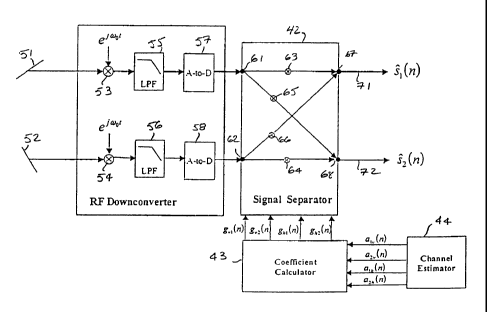
A non-limiting embodiment of a polarization diversity-based signal separation
receiver
architecture in accordance with the present invention that may be readily
incorporated with a
wireless base station's communication equipment is diagrammatically
illustrated in Figure 4,
a o as comprising four functional components:1- an RF downconverter 41, 2- a
signal separator 42,
3- a coefficient emulator 43 and 4- a channel estimator 44, each of which will
be described
individually below.
The RF downconverter 41 serves to provide the signal separator 42 with
baseband,
discrete-time samples of the signal waveforms, that are received at a
plurality (e.g., pair) of
as antenna elements 51, 52, having respectively different sensitivity
characteristics. In accordance
with a non-limiting, but preferred embodiment, antenna elements 51, 52 are
generally co-located
and have respectively different polarizations (e.g., mutually orthogonal
(90° differential)). For
purposes of providing a non-limiting example, antenna element 51 will be
referred to as a
vertically (v) polarized antenna, while antennas element 52 will be referred
to as a horizontally
30 (h) polarized antenna.
The signals received by respective antenna elements 51, 52 are multiplied in
respective
6
CA 02397131 2002-06-27
WO 01/58049 PCT/USO1/03104
mixers 53, 54 by the appropriate carrier frequency to translate (down-convert)
the RF frequency
of the received signals to baseband. These baseband signals are then filtered
in low pass filters
55, 56 to remove vestigial sideband images and limit the bandwidth. The
filtered baseband
signals are sampled and quantized in analog-to-digital converters (ADCs) 57,
58, and the
s digitized signals produced thereby are coupled to respective inputs 61, 62
of the signal separator
42.
The signal separator 42 weights and combines the baseband samples of the
vertically
and horizontally polarized received signals to estimate which signal which
signal emanates
from users and which signal emanates from userz. For this purpose, as shown in
the enlarged
to diagram of the signal separator 42 in Figure 5, the received 'vertical
polarization' signal
component r~(n) applied to its first input port 61 is coupled to a first
multiplier 63, which
multiplies the signal r~(n) by a first vertical polarization coefficient
g~l(n) produced by the
coefficient calculator 43, and to a second multiplier 65, which multiplies the
signal r~(n) by a
second vertical polarization coefficient g"z(n) produced by the coefficient
calculator 43.
is Similarly, the received 'horizontal polarization' signal component rh(n)
applied to the second
input port 62 of the signal separator 42 is coupled to a third multiplier 64,
which multiplies the
signal r,,(n) by a first horizontal polarization coefficient ghl (n) produced
by coefficient calculator
43, and to a fourth multiplier 66 which multiplies the signal r,,(n) by a
second horizontal
polarization coefficient g,,z(n) produced by the coefficient calculator 43.
The polarization
ao coefficients g~l(n), g~z(n), ghl(n) and ghZ(n) may vary with time. The
products produced by
multipliers 63 and 66 are summed in adder 67 and supplied as a first separated
signal "s,(n)
associated with users at a first output port 71. The products produced by
multipliers 64 and 65
are summed in adder 68 and supplied as a second separated signal "s2(n)
associated with user2
at a second output port 72.
zs The estimates of userl's transmitted signal may be expressed by equation
(3) as follows:
Si (n) 9'~i (n) rV(n) +gnirh (n) (3)
Substitution of equations (1) and (2) into equation (3) yields the following
equation (4):
s (n) = g (n) f (P ) l~za (n) S (n) + (P ) m2~ (n) S (n) J
m i iv i 2 a~ a
CA 02397131 2002-06-27
WO 01/58049 PCT/USO1/03104
+ghl(n) C (Pl)Wzalh(n)S1(n) + (P2)1/2a2h(n)SZ(n) l (4)
A similar expression may be readily generated for userz's signal estimate.
In order to generate the polarization coefficients g~l (n), g~z(n), g,,, (n)
and g~(n) employed
by the signal separator 42, the coefficient calculator 43 is coupled to
receive a set of channel
fading coefficients al~(n), az"(n), alh(n), azh(n) from the channel estimator
44. (The signal
s processing mechanism employed by the coefficient calculator 43 to generate
the polarization
coefficients g~,(n), g~2(n), ghl(n) and g~(n) from the channel fading
coefficients will be described
below.) While the invention is not limited to any particular mechanism to
calculate the channel
fading coefficients al"(n), az~(n), a",(n), a2,,(n), a non-limiting example is
to take advantage of the
embedded training sequences contained in each user's transmission burst.
to As a non-limiting example, the vertical and horizontal signal inputs r~(n)
and r,,(n) may
be correlated with both user's training sequences (which are known), to
produce a set of
correlation peak values. Estimates of the channel fading coefficients a,~(n),
aZ"(n), a",(n), az,,(n)
are readily derived using standard signal processing algorithms using the
correlation peak
values and the known cross-correlation between the training patterns. As an
alternative scheme,
is adaptive methods based on the received data or blind methods based on
statistical properties
may be employed.
Given these channel fading estimates, the coefficient calculator 43 computes
the set of
four polarization coefficients g~l(n), g"Z(n), gi,l(n), g,,z(n) required by
the signal separator 42 to
weight the received signals. The operation of the coefficient calculator 43
may be readily
zo understood by writing equation (3) into matrix form as equation (5) as
follows:
Is (n) I I g (n) g (n) Ilr (n) I I g (n) g (n) Ilz (n) I
1 v1 hl v v1 h1 v
is (n)J-Lg (n) g (n)JLr (n)J+Lg (n) g (n)Jlz (n)J
2 v2 h2 h v2 h2 h
I gvl (n) ghl (n) Ildlv(n) d2v(n) II S1 (n) I I gvl (n) ghl (n) IIZv(n) I
-Lg~2(n) gh2(n)JLalh(n) a2h(n)JLs2(n)J+LgV2(n) gh2(n)JLzh(n)J (5)
From equation (5), the following matrices and vectors may be defined:
s
CA 02397131 2002-06-27
WO 01/58049 PCT/USO1/03104
_I gVi (n) gh1 (n) I
G(n) LgV2 (n) gn2 (n) J
lal~(n) alh(n)I
A(n) =1a2~(n) a2h (n) J
Is1(n)I
s (n) = Ls2 (n) J
Isl (n) I
s(n) - Ls2(n)J
Iz (n)1
z (n) = Lzh (n) J
Using these matrix definitions, equation (5) may be rewritten in a compact
form as
equation (6) as follows:
s(n) - G(n) A(n) s(n) + G(n) z(n) (6)
The coefficient calculator 43 calculates the matrix G(n) such that, in the
absence of noise,
the outputs of the signal separator 42 are equal to the users' information
signals.
s Mathematically, the absence of noise implies z~(n) = zh(n) = 0 for all n.
The output of the signal
separator 43 will equal the users' information signals when the following
equations (7) and (8)
are satisfied:
S1 = sl(n)
9
CA 02397131 2002-06-27
WO 01/58049 PCT/USO1/03104
s2 = s2 ( n ) ( 8 )
This requirement is met when G(n) is the matrix inverse of A(n), namely G(n) =
A-'(n)
or
Il OI
G(n) A(n) = LO 1l (9)
From Equation (9), it can be seen that the condition the signal separator 42
must satisfy
for perfect signal separation is a set of four linear equations with four
unknowns. Equation (9)
s will always have a solution provided that the fading coefficient matrix A(N)
is full rank. In other
words, the coefficient calculator 43 uses the values obtained from the channel
estimator 44 to
form the matrix A(n) and then solves the linear equation (9).
In addition to the above-described non-limiting example of the invention shown
in
Figures 4 and 5, there are other implementations and variations of the signal
separator system
1 o that may be employed. For example, in place of the digitally implemented
baseband architecture
of Figure 4, the four multipliers 63, 64, 65, 66 and two adders 67, 68 may be
implemented using
RF multipliers (phase shift and gain control elements) and RF adders
(combiners). Such an
architecture obviates the need for the analog-to-digital converters and can
also eliminate the
need for a frequency conversion to baseband and subsequent filtering depending
on the
is hardware and the signals being processed.
As described above, the coefficient calculator 43 may be configured to
calculate the
matrix G(n) in the absence of noise. When a statistical description of
additive noise is available,
the coefficient requirements embodied in equation (9) may be modified so that
the coefficient
calculator minimizes the mean square error between s(n) and s(n). Namely, the
coefficient
2o calculator 43 is operative to calculate G(n) such that E( ~ "s(n) - s(n) ~
Z} is minimized, and takes
noise into account. The solution for G(n) is the standard minimum mean square
error and is
straightforward.
Although the architecture of Figure 4 shows only two antenna elements 51 and
52, it is
also possible to employ plural sets of antennas each having a pair of cross-
polarized elements
25 (horizontal and vertical), as diagrammatically illustrated at 81 and 82 in
Figure 6. The inputs
from these sets of cross-polarized antenna pairs can be weighted and combined
upstream of the
signal separator 42, in order to optimize the two signals applied to its input
ports 61 and 62.
to
CA 02397131 2006-06-02
PC:' I'/t 1St) 1 %t13 T t14
When the channel is subject to frequency selective fading due to multipath,
and the signals from
dilterent users have low cross-correlation properties, the frequency selective
fading may be
converted into s substantially flat fading channel by coherently combining the
observed
multipath. This coherent combining may be readily implemented as
diagrammatically illustrated
s in Figure 7, by installing a respective Rake receiver 91, 92 for each
polarization upstream ofthe
signal separator 42.
As will be appreciated from the foregoing description, the signal separation
mechanism of
the present invention is able to remedy the above-discussed co-linear
interference problem
encountered by a wireless communication system base station by exploiting
characteristics of the
To incoming signals other than their direction of arrival. As detailed above,
the invention employs
diversity gained through the use of antenna array elements having different
polarizations. When
deployed in an environment having substantially flat fading, the polarization
diversity-based
separation scheme of the invention provides an extremely simple technique for
separating co-
linear signals. Like existing multipath processing schemes, the invention can
be used in
is conjunction with multiple access waveforms (e.g., time-division or code-
division), and can
complement other signal separation methods such as array-based 'smart' beam-
forming schemes.
Non-limiting examples of such smart, array-based, beam selective systems
include those
described in co-pending U.S. Patent No. 6,411,612 issued January 25, 2002
entitled: "Selective
Modification of Antenna Directivity Pattern to Adaptively Cancel Co-channel
Interference in
2o TDMA Communication System" in the name of K. Halford et al and U.S. Patent
No. 6,188,915
issued February 13, 2001, entitled: "Bootstrapped, Piecewise-Asymptotic
Directivity Pattern
Control Mechanism Setting Weighting CoeIJicients of Phased Array Antenna" in
the name of P.
Martin et al, each of which is assigned to the assignee of the present
invention.
While I have shown and described several embodiments in accordance with the
present
2s invention, it is to be understood that the same is not limited thereto but
is susceptible to numerous
changes and modifications as known to a person skilled in the art, and I
therefore do not wish to
be limited to the details shown and described herein, but intend to cover all
such changes and
modifications as are obvious to one of ordinary skill in the art.
A signal separator overcomes co-linear interference encountered in a wireless
3o communication system base station by exploiting generally flat fading
multipath characteristics of
incoming signals. For this purpose, the invention employs diversity gained
through the use of
antenna array elements having different polarizations. An RF downconverter
provides a
11
CA 02397131 2002-06-27
WO 01/58049 PCT/USO1/03104
signal separator with baseband, discrete-time digital samples of signal
waveforms, received at
one or more pairs of diverse polarization antenna elements. The signal
separator weights and
combines the baseband signals from the vertically and horizontally polarized
received signals
produced by the RF downconverter to estimate which signals emanate from which
users. The
signal separator uses polarization coefficients supplied by a coefficient
calculator. To generate
the polarization coefficients, the coefficient calculator is coupled to
receive a set of channel
fading coefficients from a channel estimator. Estimates of the channel fading
coefficients may
be derived using standard signal processing algorithms using the peak values
and the known
cross-correlation between training patterns. The coefficient calculator
computes the polarization
coefficients required by the signal separator by means of a coefficient matrix
such that the
output of the signal separator is equal to the user's information signal.
12