Language selection

Search

Patent 2397796 Summary

Third-party information liability

Some of the information on this Web page has been provided by external sources. The Government of Canada is not responsible for the accuracy, reliability or currency of the information supplied by external sources. Users wishing to rely upon this information should consult directly with the source of the information. Content provided by external sources is not subject to official languages, privacy and accessibility requirements.

Claims and Abstract availability

Any discrepancies in the text and image of the Claims and Abstract are due to differing posting times. Text of the Claims and Abstract are posted:

  • At the time the application is open to public inspection;
  • At the time of issue of the patent (grant).
(12) Patent: (11) CA 2397796
(54) English Title: METHOD AND APPARATUS FOR GRINDING OF PARTICULATE MATERIAL
(54) French Title: PROCEDE ET APPAREIL DE BROYAGE D'UNE SUBSTANCE PARTICULAIRE
Status: Deemed expired
Bibliographic Data
(51) International Patent Classification (IPC):
  • B02C 4/02 (2006.01)
  • B02C 4/28 (2006.01)
(72) Inventors :
  • TOUBORG, JORN (Denmark)
(73) Owners :
  • F.L. SMIDTH & CO. A/S (Denmark)
(71) Applicants :
  • F.L. SMIDTH & CO. A/S (Denmark)
(74) Agent: BORDEN LADNER GERVAIS LLP
(74) Associate agent:
(45) Issued: 2009-01-13
(86) PCT Filing Date: 2001-01-19
(87) Open to Public Inspection: 2001-08-02
Examination requested: 2005-08-26
Availability of licence: N/A
(25) Language of filing: English

Patent Cooperation Treaty (PCT): Yes
(86) PCT Filing Number: PCT/IB2001/000057
(87) International Publication Number: WO2001/054818
(85) National Entry: 2002-07-15

(30) Application Priority Data:
Application No. Country/Territory Date
PA 2000 00147 Denmark 2000-01-28

Abstracts

English Abstract


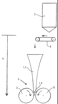
A description is provided of a method as well as
an apparatus for grinding particulate material, such as cement raw
materials, cement clinker or similar materials, in a roller mill (1)
by subjecting the material to pressing action in a zone (13)
between opposite, rotating surfaces where the material is directed to
the grinding zone via a feed shaft (11). The method is peculiar in
that the material in the feed shaft (11) is accelerated through the
action of gravity to a desired velocity without involving essential
air admixture, whereas the apparatus is peculiar in that the feed
shaft is essentially of a vertical configuration, with a downwardly
reduced cross-section, where the reduction of the shafts
cross-sectional circumference per height unit is downwardly decreasing.The
described configuration of the feed shaft has, surprisingly, proved
that the material over a given height of fall may attain high
velocities and that this is achievable without involving admixture of
air into the material. It has thus been established that it will be
possible for the material to attain velocities which are close to the
velocity achievable in connection with the free fall of individual
particles.


Image


French Abstract

L'invention concerne un procédé et un appareil permettant de broyer une substance particulaire, telle que des matières premières de ciment, du ciment non broyé ou analogues, dans un broyeur à cylindres (1), lequel procédé consiste à soumettre ladite substance à une force de pression dans une zone (13) située entre des surfaces tournantes opposées où la substance est dirigée vers la zone de broyage au moyen d'une barre de chariotage (11). Le procédé de l'invention est caractérisé en ce que la substance placée dans la barre de chariotage (11) est accélérée sous l'action de la gravité jusqu'à une vitesse recherchée sans admixtion importante d'air, l'appareil de l'invention étant caractérisé par le fait que la barre de chariotage est en configuration sensiblement verticale, avec une section transversale réduite vers le bas, la diminution de la circonférence transversale de la barre par unité de hauteur décroissant vers le bas. La configuration de la barre de chariotage décrite a montré, d'une manière surprenante, qu'au-delà d'une hauteur ou d'une chute donnée la substance peut atteindre des vitesses élevées, et ce sans entraîner une admixtion d'air dans la substance. Ainsi, il a été montré que la substance peut atteindre des vitesses proches de la vitesse obtenue dans le cadre d'une chute libre des particules individuelles.

Claims

Note: Claims are shown in the official language in which they were submitted.


7
CLAIMS:

1. An apparatus for grinding of particulate material
which apparatus comprises a roller mill by which the
material to be ground is subjected to a pressing action
in a zone between opposite, rotating surfaces as well as
a shaft for feeding particulate material to the grinding
zone of the roller mill, the shaft being of a
substantially vertical configuration and with a
downwardly reduced cross-section wherein the reduction of
the shaft's cross-sectional circumference per height unit
is downwardly decreasing.

2. An apparatus according to claim 1 wherein the cross-
sectional area of the shaft as a function of the height
of fall is in accordance with the formula

Image where
A is the cross-sectional area
V is the volume flow
g is the gravity acceleration
h is the height of fall
A is within the range 0 and 0.2.

3. An apparatus according to claim 2 wherein A is lower
than 0.1.

4. An apparatus according to claim 1 wherein the shaft is
made up of at least 3 pyramical or conical sections.


8
5. An apparatus according to claim 1, 2 or 3 wherein the
reduction of the cross-sectional circumference of the
shaft exhibits a continuous downwardly decrease.

6. An apparatus according to claim 5 wherein the shaft is
of a trumpet-shaped configuration.

7. An apparatus according to any one of claims 1 to 6
wherein the particulate material is cement or cement
clinker.

Description

Note: Descriptions are shown in the official language in which they were submitted.


CA 02397796 2008-08-14
1

METHOD AND APPARATUS FOR GRINDING OF PARTICULATE MATERIAL
The present invention relates to an apparatus for grinding
of particulate material such as cement raw materiafs,
cement clinker or similar materials, in a roller mill, such
as a roller press, ring-roller mill, vertical mill or a
similar unit. The shaft being of substantially vertical
configuration and with a downwardly reduced cross-section.

An apparatus of the aforementioned kind is prior art.

In recent years, developments in grinding technology have
primarily been devoted to impriving the cost efficiency of
the grinding process. In this context, the primary focus
has been to improve the operating economy of the grinding
process and to reduce the capital cost of the grinding
machines relative to their capacity ratings. A method
widely used to lower the investments costs involves
uprating of the operating speed of a machine, and hence its
productivity. Needless to say, the operating speed of a
machine can only be increased up to a certain point, and,
furthermore, it is a recongnized fact that problems are
likely to occur in connection with the operation of, for
example, a roller press if the peripheral velocity of the
rollers is increased arbitrarily.

Such operating problems may be ascribable to many different
causes. On explanation could be the difficulty of achieving
an acceleration of the material shich is to be ground in
the roller press to an extent which corresponds to the
peripheral velocity of the rollers. Such acceleration of
the material is usually achieved by means of the rollers by
physical contact with the latter and/or through the action
of gravity. However, the capability of the rollers is
restricted to a very short range of operation, thereby


CA 02397796 2002-07-16

F ~ 8~h 'at ''~ PCT/IB01/00057
PCT intsmat:,:?r :,)itcatipn
--- 10-01-2002
severly limiting the rate of acceleration, and in a shaft
the force of gravity will either be counteracted by the
friction of the material against the shaft and/or the
friction present in the material itself. Also, acceleration
accomplished in a traditional shaft will also entail
significant admixture of air, which is undesirable, and
this will also adversely affect the grinding process. Use
of a vertical shaft with a circular or rectangular cross-
section and with an identical cross-sectional area across
the entire length will enable the force of gravity to
accelerate the material to a high velocity, but in this
scenario there will be a simultaneous increase in the
distance between the particles, thereby decreasing the
density of the material an involving air admixture. By
using a shaft of a pyrimidal or conical configuration, it
will be possible to maintain the distance between the
particles, but in a shaft of this type the material will be
influenced by forces of friction which are so substantial
that the terminal velocities attainable are quite small. In
such ordinary shafts the cross-sectional circumference is a
liniarly decreasing function of the height. The reduction
of the cross-sectional circumference per height unit thus
remains constant for these shafts.

It is the objective of the present, invention to provide an
apparatus for remedying the aforementioned deficiencies.
This is achieved by an apparatus of the kind mentioned in
the introduction, and being characterized in that the
reduction of the shaft's cross-sectional circumference per
heiht unit is downwardly decreasing.

The described configuration of the feed shaft has, -
surprisingly, proved that the material over a given height
AMENDED SHEET


CA 02397796 2002-07-15

WO 01/54818 PCT/IB01/00057
3
of fall may attain high velocities, and that this is
feasible without involving admixture of air into the
material. It has thus been established that it will be
possible for the material- to attain velocities which are
close to t he velocity achievable in connection with the free
fall of individual particles.

The material can be accelerated to a velocity of more than
1.5 m/s. However, it is preferred that the material be
accelerated to a velocity of more than 5 m/s, and preferably
of more t:an 10 m/s.

An example of the cross-sectional characteristics according
to the invention is known from the form of a free-falling
water jet, for example from a slow-running water tap. At the
top, at the outlet of the water tap, the water flow rate is
quite small, with the width of the water jet corresponding
roughly to the outlet. Further downstream of the jet the
force of gravity has increased the water flow rate, but
since the water flow throughout the jet is the same, and
since the density throughout the jet is also the same, this
means that the cross-section of the water jet is smaller. In
this way the water jet will attain an almost hyperbolic
shape and the characteristics of the cross-sectional area as
a functior_ of the height of fall can be expressed by means
of the formula:
V
(1) A=~1+0) _gh , where
A is the cross-sectional area

V is the volume flow
g is the gravity acceleration
h is the ~eight of fall
A is a correction element which describes the friction in
the mater=al, assuming for water a small value which is
close to C


CA 02397796 2002-07-15

WO 01/54818 PCT/IB01/00057
4
The water jet must be assumed to roughly circular and,
therefore, its circumference can be calculated on the basis
of the formula:


(2) O=;TD=TC 4(1+0) ~ 7 h , where

0 is the circumference
D is the diameter of the water jet
As it appears from the aforementioned formula, the
circumference is proportional not to the height of fall but
to the height of fall to power =1/.

According to the invention it is preferred that the shaft be
configured so that its cross-sectional area as a function of
the fall of height is essentially as defined in the formula
above. To make allowance for the friction which occurs when
feeding particulate material via a shaft according to the
invention, the correction element A must be within the
range 0 and 0.2, preferably lower than 0.1.

The shaft may, for example, be made up of a number of
pyramidal or conical sections so that the reduction of the
cross-sectional circumference of the shaft exhibits a
gradual, downwardly decreasing trend. To ensure that the
shape of such a shaft does not deviate too much from the
formula (1) indicated above, it is preferred that the number
of sections incorporated is at least 3, but preferably at
least 5, and most preferably at least 10.

However, it is preferred that the reduction of the cross-
sectional circumference of the shaft exhibits a continuous
downwardly decrease, and that for example the shaft is of a
3_5 trumpet-shaped configuration.


CA 02397796 2002-07-15

WO 01/54818 PCT/IB01/00057
In principle, it will be possible to use the shaft according
to the invention fcr conveying any particulate material from
one level to a lower level by the action of gravity, and for
this purpose the shaft should be of a substantially vertical
5 configuration, with a downwardly reduced cross-section where
the reduction of the cross-sectional circumference of the
shaft is downwardly decreasing.

The invention will be explained in further details in the
followina with reference being made to the drawing, which is
diagrammatical, and where

Fig. 1 shows a roller press installaticn comprising a feed
shaft according to the invention.
In Fig. 1 is seen a roller press installation comprising a
roller press 1 with two oppositely rotating rollers 3 and 5.
During the operation of the roller press, the material to be
ground is fed from a bin 7 via a feed conveyor 9 and a feed
shaft 11 to a grinding zone 13 between the rollers 3 and 5.
According to the invention the depicted shaft is formed with
a downwardly reduced cross-section in such a way that the
reduction of the shaft"s cross-sectional circumference per
height unit is also downwardly decreasing. Ideal_y the shaft
is formed with a downwardly decreasing cross-section which
is inversely proportional to the steadily downwardly
increasing velocity of the material due to the gravity-
induced acceleration. 1--lence it will be possible for the
material to achieve a velocity close to the velocity of a
free fall without admixture of air, allowing the roller
press to be operated at higher roller velocities, thereby
increasing its rate of production.

The applicant filing the present patent application has
conducted tests with a shaft configured in accordance with
the aforementioned auidelines, with a final cross section of
0.1 x 0.1- metr=s and a heiaht Of 5 metres, and has recorded


CA 02397796 2002-07-15

WO 01/54818 PCT/IB01/00057
6
a materiai velocity which is close to 10 m/s withcut air
admixture.

Representative Drawing
A single figure which represents the drawing illustrating the invention.
Administrative Status

For a clearer understanding of the status of the application/patent presented on this page, the site Disclaimer , as well as the definitions for Patent , Administrative Status , Maintenance Fee  and Payment History  should be consulted.

Administrative Status

Title Date
Forecasted Issue Date 2009-01-13
(86) PCT Filing Date 2001-01-19
(87) PCT Publication Date 2001-08-02
(85) National Entry 2002-07-15
Examination Requested 2005-08-26
(45) Issued 2009-01-13
Deemed Expired 2011-01-19

Abandonment History

There is no abandonment history.

Payment History

Fee Type Anniversary Year Due Date Amount Paid Paid Date
Application Fee $300.00 2002-07-15
Maintenance Fee - Application - New Act 2 2003-01-20 $100.00 2002-09-06
Registration of a document - section 124 $100.00 2002-09-12
Maintenance Fee - Application - New Act 3 2004-01-19 $100.00 2004-01-15
Maintenance Fee - Application - New Act 4 2005-01-19 $100.00 2005-01-13
Request for Examination $800.00 2005-08-26
Maintenance Fee - Application - New Act 5 2006-01-19 $200.00 2006-01-13
Maintenance Fee - Application - New Act 6 2007-01-19 $200.00 2007-01-10
Maintenance Fee - Application - New Act 7 2008-01-21 $200.00 2008-01-11
Final Fee $300.00 2008-10-29
Maintenance Fee - Patent - New Act 8 2009-01-19 $200.00 2009-01-15
Owners on Record

Note: Records showing the ownership history in alphabetical order.

Current Owners on Record
F.L. SMIDTH & CO. A/S
Past Owners on Record
TOUBORG, JORN
Past Owners that do not appear in the "Owners on Record" listing will appear in other documentation within the application.
Documents

To view selected files, please enter reCAPTCHA code :


To view images, click a link in the Document Description column. To download the documents, select one or more checkboxes in the first column and then click the "Download Selected in PDF format (Zip Archive)" or the "Download Selected as Single PDF" button.

List of published and non-published patent-specific documents on the CPD .

If you have any difficulty accessing content, you can call the Client Service Centre at 1-866-997-1936 or send them an e-mail at CIPO Client Service Centre.


Document
Description 
Date
(yyyy-mm-dd) 
Number of pages   Size of Image (KB) 
Description 2008-08-14 6 222
Representative Drawing 2002-07-15 1 8
Abstract 2002-07-15 2 70
Claims 2002-07-15 2 52
Description 2002-07-15 6 219
Drawings 2002-07-15 1 6
Cover Page 2002-10-24 2 46
Description 2002-07-16 6 224
Claims 2002-07-16 2 41
Claims 2007-03-28 2 33
Claims 2008-02-25 2 37
Representative Drawing 2008-12-22 1 3
Cover Page 2008-12-22 2 46
Correspondence 2008-08-14 2 81
PCT 2002-07-15 3 94
Assignment 2002-07-15 3 87
Assignment 2002-09-12 2 67
PCT 2002-07-16 3 172
Prosecution-Amendment 2002-07-16 5 154
Correspondence 2004-03-09 1 17
Prosecution-Amendment 2005-08-26 1 20
Prosecution-Amendment 2007-02-20 2 59
Prosecution-Amendment 2007-03-28 4 113
Prosecution-Amendment 2007-10-10 2 61
Prosecution-Amendment 2008-02-25 5 158
Correspondence 2008-07-14 1 21
Correspondence 2008-10-29 1 34