Note: Descriptions are shown in the official language in which they were submitted.
CA 02397897 2002-07-19
180100048
0:-05-2002 RI 09:27 FU 512 2643735
Docket No. 11WROW002T
TITLE: MULTI-CARRIER ARRANGEMENT FOR HIGH SPEED DATA
SPECff1CiTION
BACKGROUND
1. Technical Field
The present invention relates generally to cellular wireless communication
networks;
and more particularly to the transmission of voice communications and data
communications in such a cellular wireless communication network.
2. Related Art
Wireless networks are well known. Cellular wireless networks support wireless
communication services in many populated areas of the world. Satellite
wireless networks
are known to support wireless communication services across most surface areas
of the
Earth. While wireless networks were initially constructed to service voice
communications,
they are now called upon to support data communications as well.
The demand for data communication services has exploded with the acceptance
and
widespread use of the Internet While data communications have historically
been serviced
via wired connections, wireless users are now demanding that their wireless
units also
support data communications- Many wireless subscribers now expect to be able
to 'surf'
the Internet, access their email, and perform other data communication
activities using their
cellular phones, wireless personal data assistants, wirelessly linked notebook
computers,
and/or other wireless devices. The demand for wireless network data
communications will
only increase with time. Thus, wireless networks are currently being
created/modificd to
service these burgeoning data communication demands.
Significant performance issues exist when using a wireless network to service
data
communications. Wireless networks were initially designed to service the well-
defined
requirements of voice communications. Generally speaking, voice communications
require
a sustained bandwidth with minimum signal-to-noise ratio (SNR) and continuity
requirements. Data communications, on the other hand, have very different
performance
requirements. Data communications are typically bursty, discontinuous, and may
require a
relatively high bandwidth during their active portions. To understand the
difficulties in
servicing data communications within a wireless network, consider the
structure and
operation of a cellular wireless network
1
AMENDED SHEET
r._c _--~.nomtInnno 1R=no f-mat_nr_:I1b4 N_W_b
03-05-2002 CA 02397897 2002-07-19 .801000481
vai V.a~ vc rAI 09:27 FAX 512 2643735
Docket No. U963ROW003T
Cellular wireless networks include a `network infiutruc Lure" that wirelessly
communicates with user terminals within a respective service coverage area.
The network
infrastructure typically includes a plurality of base stations dispersed
throughout the service
coverage area, each of which supports wireless communications within a
respective call (or
set of sectors). The base stations couple to base station controllers (BSCs),
with each BSC
serving a plurality of base stations. Each BSC couples to a mobile switching
center (MSC).
Each BSC also typically directly or indirectly couples to the Internet
In operation, a user terminal communicates with one (or more) of the base
stations.
A BSC coupled to the serving base station routes voice communications between
the MSC
and the serving base station. The MSC routes the voice communication to
another MSC or
to the public switched telephone network (PSTN). BSCs route data
communications
between a servicing base station and a packet data network that may couple to
the Internet
The wireless link between the base station and the user terminal is defined by
one of
a plurality of operating standards, e.g., AMPS, TDMA, CDMA, GSM, etc. These
operating
standards, as well as new 3G and 4G operating standards define the manner in
which the
wireless link may be allocated, setup, serviced and torn down. These operating
standards
must set forth operations that will be satisfactory in servicing both voice
and data
communications.
The wireless network infrastructure must support both low bit rate voice
communications and the higher bit rate data communications. More particularly,
the
network infrastructure must transmit low bit rate, delay sensitive voice
communications
together with high data rate, delay tolerant rate data communications. While
voice
communications typically have a long hold time, e.g., remain active for longer
than two
minutes on the average, high data rate/delay tolerant data communications are
buasty and are
active only sporadically. As contrasted to the channel allocation Yequirements
of voice
communications, channels must be frequently allocated and deallocated to the
data
communication in order to avoid wasting spectrum. Such allocation and
deallocation of
channels to the data communications consumes significant overhead.
To increase throughput of conventional cellular wireless networks, the
allocated
frequency spectrum is oftentimes subdivided into a plurality of sub spectrums,
each of
which is serviced by a respective carrier. With such a subdivision, the number
of user
terminals that may be serviced increases relative to the number that may be
serviced by a
single carrier. Further, Inulticarrier systems are less sensitive to
dispersion and frequency
2
AMENDED SHEET
nnrncJnnnC) 1 F=()o h-mpt.nr.:U04 r.uua
CA 02397897 2002-07-19
03-05-2002 FRI 09:29 FAX 512 2643795 180100048
Docket No.11963ROWO02T
selective fading. Thus, gains are achieved in systems of this type by
servicing a greater
number of user terminals at any given time. Further, the overhead consumed in
allocating/deallocating channels significantly may also decrease in a system
of this type
since a. greater number of user terminals may be serviced at any one time.
However, the
bandwidth available for communications on each carrier is less than it would
be for a single
carrier using the full spectrum. Thus, the gains achieved in reducing
allocation/deallocation
overhead are offset by reduced throughput t
It would therefore be desirable to provide a communication system that
efficiently
uses a plurality of carriers to service communications with minimal waste of
spectral
capacity- Further, it would also be desirable to provide a communication
system that
services both delay sensitive low bit rate voice communications and delay
tolerant data
communications upon a plurality of carriers without requiring significant
additional
overhead resources.
SUMMARY OF TEE INVENTION
The system and method of the present invention efficiently uses a plurality of
carriers by assigning user terminals to the plurality of carriers so that a
minimum grade of
service is met and so that throughput is maximized. To accomplish these goals,
each
serviced user terminal reports the channel quality of each of the plurality of
carriers to a
servicing base station(s). The reported channel qualities may then be
converted to
maximum supported data rates for each of the user terminals and each of the
carriers. These
data rates are then used to allocate data service levels and data rates for
each of the user
terminals so that a minimum grade of service is met for each of the user
terminals. Forward
link transmissions, e.g., frames/data packets carried on forward channels (F-
CHs), are then
constructed and transmitted to meet the allocations. With assignments made in
this
fashion, throughput across the multiple carriers is maximized.
According to one aspect of the present invention, each carrier supports a
different
maximum data rate per user at any given time and includes a scheduler that
assigns a data
rate allocation for each carrier based on criteria. The criteria of optimizing
total throughput
is achieved by minimizing the number of frames being used to satisfy the
transmission
needs of all the users. In this fashion, minimum service levels are met and
throughput is
maximized.
In one embodiment of the present invention, a Time Division Multiplexed (TDM)
3
AMENDED SHEET
Fmcrf 1h,9 Fmof r,r nRA P nn7
CA 02397897 2002-07-19
03-05-2002 RI 09: 28 FAX 512 2643735 180100048
Docket No.11963ROW002T
superfiamelframe structure is employed to catty data and voice communications
on the F-
CHs. This superframe/frame structure is optimized for servicing both delay
tolerant, high
data rate data transmissions, and delay intolerant, fixed rate voice
transmissions- The TDM
frame structure of the present invention supports flexible framing of
transmissions that
include both the lower data rate, delay intolerant voice communications as
well as the delay
tolerant higher data rate data communications using sub-framing operations.
Thus, the
system and method of the present -invention provides significant benefits for
both data
communication only wireless traffic and for a combination of voice
communication and data
communication wireless traffic. This TDM frame structure may include a self-
indication of
its contents such that user terminals may determine whether the TDM frame
carries its voice
or data communications via a simple inspection of the TDM frame itself With
this
structure, any overhead that was previously required to allocatofdeallocate
channels is no
longer consumed.
The TDM frame structure of the present invention employs data rate matching so
that different data rates may be supported for different user terminals
sharing the TDM
frame structure. When used on the forward link, a base station selects data
rates for each of
a plurality of serviced user terminals based upon the channel qualities of the
F-CHs reported
by the user terminals for the plurality of carriers. Then, the basc
station/network
infirastructure constructs a plurality of superfiames to service required
voice and data
communications on the plurality of F-CHs for a given time period such that sui
iaient
service levels are met.
Other features and advantages of the present invention will become apparent
from
the following detailed description of the invention made with reference to the
accompanying
drawings.
BRIEF DESCRIPTION OF THE DRAWINGS
A better vndding of the present invention can be obtained when the following
detailed description of the preferred embodiment is considered in conjunction
with the
following drawings, in which:
FIG. I A is a system diagram illustrating a portion of a cellular wireless
network
constructed according to the present invention;
FIG. IB is a block diagram illustrating the structure of adjacent carriers
upon which
high speed data frames are modulated according to the present invention;
4
AMENDED SHEET
r - r .nn inc loin 7a=0 Gmn-F nr =f1F A P f 11 N
CA 02397897 2002-07-19
03-05-2002 FRI 09:28 FAX 512 2643735 180100048
Docket No.11963ROW002T
FIG. 2 is a logic diagram illustrating operation according to the present
invention in
allocating voice communications and data communications to a plurality of
carriers;
FIG. 3 is a block diagram illustrating the structure of superframes and high
speed
data frames according to the present invention;
FIG. 4 is a block diagram illustrating the structure of a packet according to
the
present invention that is transmitted on a carrier,
FIG. 5 is a logic diagram illustrating operation according to the present
invention in
constructing a plurality of superframes, each of which will be carried upon a
separate carrier
during a common time interval;
FIG. 6 is a block diagram showing an example of an apparatus for generating
and
processing the superfiame structure of the invention for a single carrier,
FIG. 7 is a block diagram showing an example of an apparatus for generating
three
superfiame structures according to the present invention, each of which is
carried upon a
separate carrier and transmitted during a common time interval;
FIG. 9 is a block diagram illustrating a base station constructed according to
the
present invention; and
FIG. 9 is a block diagram illustrating a user terminal constructed according
to the
present invention.
DETAILED DESCRZPnOrr OF THE DRAWINGS
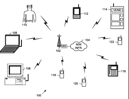
FIG. IA is a system diagram illustrating a portion of a cellular system 100 in
which a
base station 102 services a plurality of user terminals 106-122 on a plurality
of carriers
corresponding to a plurality of forward channels (F-CHs) according to the
present invention.
The cellular system 100 infrastructure shown includes a base station 102 and a
network
infrastructure 104. These components are generally known and will be described
only as
they relate to the teachings of the present invention. The cellular system 100
operates
according to a CDMA standard that has been modified according to the present
invention,
e.g., IS-95B, IS-2000, 3GPP, W-COMA, or another CDMA standard that has been
modified
according to the operations described herein. In particular, the high speed
data (HSD) 1xEV
standard data only (DO), the HSI) 1xEV standard data and voice (DV), and the
3GPP HSD
standard may operate according to some of the aspects of the present
invention.
The base station 102 provides wireless service within a corresponding
geographic
area (e.g., cell or sector(s)) on the plurality of carriers. The base station
102 establishes a
5
AMENDED SHEET
C--.C __ : , . no me rnnnn IC-On c...r,4 -- ^ nP A 0 nnQ
CA 02397897 2002-07-19
03-05-2002 FRI 09:29 FAX 512 2643735 IB0100048
Docket Ne. 11963ROW002T
plurality of forward links and at least one reverse link with the user
terminals 106-122.
Once these links are established, the base station 102 transmits voice
communications and
data communications to the user terminals 106-122 on the plurality of F-CHs.
Likewise, the
user terminals 106-122 transmit voice communications and data communications
to the base
station 102 on the reverse link(s).
Some of the user terminals (e.g., voice terminals 118, 120 and 122) service
only
voice communications. Alternatively, other of the user terminals (e.g., data
terminal 112,
vending machine 114 and credit card terminal 116) service only data
communications.
Further, at least some of these users terminals (e.g., desktop computer 106,
laptop computer
108, and wearable computer 110) service both voice communications and data
communications.
Each of the F-CHs is carried upon a respective carrier, e.g., Carrier 1,
Cartier 2,
Cartier 3, etc. In an embodiment that will be described herein, the carriers
are adjacent to
one another in frequency. However, adjacency of the carriers is not a
requirement of the
present invention. Each of these F-CHs is shared by a plurality of user
terminals in a Time
Domain Multiplexed (TDM) fashion. The base station 102 may service the F-CHs
in each
of a plurality of sectors, with each sector servicing a subset of the user
terminals 106-122.
To accomplish sharing of the F-CHs, each F-CH may use a TDM superframe
structure that includes a plurality of frames. This superframelframe structure
flexibly
accommodates both voice communications and data communications, without
adversely
impacting the requirements of the voice communications. Further, this
superframe/frame
S'Iructure efficiently supports data communications without wasting any
valuable allocated
bandwidth and by fairly allocating the available allocated bandwidth among the
serviced
user terminals. This TDM frame structure may also include one or more
indications of its
contents that are employed by the user terminals to determine whether the TDM
frame
structure includes voiceldata for the user terminal and, if so, at what
locations in the TDM
frame the voice/data is located and, optionally, at what data rate the
voiceldata is sent. The
user terminal may then receive the voice/data based upon this indication.
FIG. lB is a block diagram illustrating the structure of adjacent carriers
that service
F-CHs upon which high speed data frames are modulated according to the present
invention.
The structure of FIG. 1B includes parallel channels that deliver separate data
flows
simultaneously using the superframe/frame structure of the present invention.
Three such
carriers of the multi-carrier are shown, namely, Carrier-1, Carrier-2, and
Carrier-3. A
6
AMENDED SHEET
Finaf ;o;+=n~/n~/~~(t(i~) in=un Fmr nr =nRA P ntn
CA 02397897 2002-07-19
03-05-2002 FRI 09:29 FAX 512 2.643735 IB0100048
Docket No.11963ROW002T
characteristic of the multi-carrier is the traission of data flows on
multiple, separately
modulated carriers. Each cagier has different channel conditions is that the
channel quality,
e.g., C/I, for a given subscriber is not the same for each carrier.
Independent/carrelated
fading arises in each carrier during throughput of data flows on the carriers.
In other words,
each carrier can support a maximum data rate per user that is not the same for
each.
For these reasons, it is desirable to service user terminals on carriers that
are
favorable for the user terminal. Further, it is desirable to manage the
operation of each
cagier to optimize the operation of the cell/sector serviced by the carriers.
For example, it
may be advantageous in some operations to place all voice communications on
one of the
carriers, e.g., Carrier-1, and to place data communications on the other
carriers, e.g., Carrier-
2 and Carrier-3. Further, with these operations, not all of the carriers maybe
needed at any
given time. To avoid adjacent band interference, it may be desirable to
temporarily
discontinue transmissions on one of the carriers, e.g., Carrier-2, when it is
not required
during low loading periods.
FIG. 2 is a logic diagram illustrating operation according to the present
invention in
allocating voice communications and data communications to a plurality of
carriers. The
base stationliniiaatructure listens for channel quality indications/data rate
indications from a
plurality of serviced user terminals (step 202). A plurality of user terminals
serviced by a
wireless network receives pilot signals from one or more base stations. In
most
implementations, a pilot signal will be transmitted from each sector of each
base station and
received by a plurality of terminals within transmission range. However, in
other
implementations, at least one base station sector includes a plurality of
beams, each of
which includes a transmitted pilot signal. Based upon measured strengths of
received pilot
signals, measured interference, and thresholds stored internal to the user
terminal, each user
terminal reports the C/I ratio(s) for the pilot signals to a base station
servicing its reverse
link (step 204). Alternately, the user terminals may calculate a maximum data
rate at which
they could receive data on each of the carriers and report this maximum data
rate as the
channel quality indication. The base station receives channel quality
indications from most,
if not all of its serviced user terminals. Once the period of time expires,
operation will
proceed from step 204.
With the channel quality indications received from the plurality of user
terminals,
the base station/network infrastructure determines a data rate that may be
supported for each
reporting user terminal on each serviced carrier (step 206) for those
terminals that reported a
7
~~ /nr AMENDED ED SHEET
Pmof -o i+ = ^; / n'l /9lfl^^ 7 111 I1 -.n P .n4 ,b. - n A P m 1
CA 02397897 2002-07-19
03-05-2002 FRI 09:29 FAX 512 2643733 IB0100048
Docket Na 11963ROW002T
C/i for the carrier. Next, the base station/next infrastructure organizes the
user terminal
maximum data rates according to carrier (step 208). Based upon the data rates
for the user
terminals and the carriers, and additional information regarding required
minimum grades of
service for the plurality of user terminals, the base station/network
infrastructure allocates
frames to maximize multi-carrier throughput (step 212).
For example, each of the user terminals may have a request to receive a
minimum bit
rate that is to be met in each supetfreme. Alternately, each of the user
terminals may be
guaranteed a certain rate over time. In allocating packets/frames to the
plurality of user
terminals, the base station/netwwork infrastructure meets the minimum grade of
service
required for each user terminal and also maximizes the multi-carrier
throughput Further, in
this allocation, any packeb/frsanes that are not required to meet the minimum
grade of
service for each user terminal are also allocated to the user terminals. These
allocations may
be based upon respective grades of service, fairness, or another criteria.
Then, based upon the packet/frame allocations, the base -station/network
infrastructure assigns frame locations and data rates on the plurality of
carriers to the user
terminals (step 214). Finally, the base station constructs and transmits
flames on the
plurality of carriers according to the frame location/data rate assignments.
The process is
then repeated.
In one embodiment of a priority system for assigning packets/frames, certain
higher
priority users may be assigned more than one available frame for every one
frame assigned
to other lower priority users. This concept can be generalized. Classes of
service can be
defined for the services supported. A user or terminal could support several
(logical)
connections with a different service and service class for each connection.
For example,
service classes 1, 2, and 3 could have frames allocated in the ratio of
1:n2:n3. With this
allocation, on the average, for every frame assigned to a user in service
class 1, n2 frames
are assigned to a user in service class 2 and n3 frames are assigned to a user
in service class
3.
The scheduling algorithm is intended to maximize aggregate throughput based on
the different data rates that the carriers can handle per user and based on
the different classes
of service, latency requirements and different data rates that the users
require. In this
manner, the scheduler (further described with reference to FIG. 7) decides
which user is to
receive information in a frame for a particular carrier by optimizing the
order in which
8
AMENDED SHEET
Fmpf _;,P t:fl^If Riii ri ih:-n i~rnOf nr 'f1FA P f119
CA 02397897 2002-07-19
03-05-2002 FRI 09:30 FAX 512 2943735 IB0100048
Docket No.11%3ROW002T
carriers are selected to carry communications to the user terminals. The
communications to
a particular user terminal can be in any frame on any carrier.
For instance, if only a single user needs to transfer data, then the user may
use a
fame from each, of the carriers. Such was not possible in conventional TDM
structure, in
which each user would have to keep using the frames for the same carrier.
Thus, as
compared with conventional TDM structures that confine users to frames of a
single carrier,
the maximum data rate in accordance with the present invention would increase
by a factor
of N per user, where N represents the total number of carriers available.
The assignment of the frames to carriers is based on a calculation of the
aggregate
throughput for all users. The goal is to maximize the aggregate throughput.
This will
**>;i+im e the total number of frames that need to be used by the users
overall to effect their
simultaneous transmission. The scheduler gives users the ability to share any
of the frames
in the channels as would result in better optimization of the overall
throughput subject to
constraints due to class of service priority and latency requirements. That
is, to attain the
best throughput through the channels, the number of frames being used to
satisfy the needs
of all the users should be minimized.
The selection of the carrier and the data rate is in accordance with joint
scheduling
criteria, whether it be in accordance with fairness criteria to give aa31
users the same access or
on priority criteria to give certain users more access and maintain certain
latency
requirements. In both cases, a percentage of frames is allocated for each
user. The
percentage assigned per user may vary dynamically in response to channel
conditions and
latency constraints.
One example of a scheduling algorithm that maximizes the total throughput of
all
users among all carriers includes a case for a 3-carrier and N-terminal
arrangement. Each
terninal reports the measured CII for each carrier. The following matrix of
Equation (1)
results from mapping the C/I to the data rate R (where the superscript
identifies the user and
the subscript identifies the carrier):
ai,1 C/i12 ..... GI1N R11 R12 ..... R1N
C/L1 Gii ..... C/I211' 4 R2' It? ..... Rzx
C/Y31 CA32 ..... C/I3111 R3' R32 ..... e
For a specific frame interval the scheduler assigns the 3 frames available to
terminals
i, j, k from the N terminals in the system based on certain criteria.. The
following aggregate
rates are calculated:
9
AMENDED SHEET
Fmof 7Ci t,nq/n;/mm? is i G.m,4 , -MA D n1Q
CA 02397897 2002-07-19
03-05-2002 RI 09:30 FAX 312 2643735 180100048
Docket No.11963R0W002T
Rate (L j, k) = RI'+R) + R3k
Rate (L X j) = Rif +RP+ R31
Rate (j, i, k) ' R11 +R21+ Rik
Rate (1, k, i) - R j + Rak+ Rai
Rate (k, i, j) = Rri+ Rz' + R~
j, i) - R,k +Rz + R3'
Rate Or.
Where Rate (1, m, n) is the aggregate data rate when user terminals 1, m, and
n are
assigned to carriers 1, 2, and 3, respectively. The rates are then compared
and the maximum
aggregate rate R(imax, jmax, kmax) - R1 m + R2j= + RP= is obtained. The
scheduler .
assigns the terminals imax, jmax and kmax to the carriers 1, 2 and 3
respectively. Data is
transmitted to the terminals imax, jmax and kmax at rate RI"' on carrier 1,
R)EM on carrier
2 and R3 on carrier 3 respectively. The scheduler maximizes the aggregate data
rate for
a specific frame interval. Note that this scheduling is still applicable if
multiple frames are
assigned to one terminal for a specific frame interval.
FIG. 3 is a block diagram illustrating the structure of supc&wues and high
speed
data (HSD) frames according to the present invention that are transmitted on
the plurality of
carriers. The supaIrame structure is transmitted on each of the F-CHs and fits
within the
other requirements placed upon the forward links produced by the base station
102. In
particular, every 400 ms, the base station 102 transmits a broadcast channel
(BCCH) field.
In one embodiment, the BCCH field is only included on one of the F-CHs.
However, in
another embodiment, the BCCH field is included on each of the F-CHs. In either
case, an
integer multiple of the superframes fits within the timing requirement of the
BCCH. As
described herein, each sup=frame is 20 ms in length and includes 16 HSD
frames, each
having a duration of 1.25 ms. With this stnicture, the BCCH field is
transmitted every 400
ms using 8 HSD frames at a data rate of 76.8 kbps. Further, every 20th 20 ms
superframe
will include the BCCH field. Each 20 ms superfrazne may include voice
communications
and/or data communications.
The superframe structure is shared among a plurality of users serviced on the
corresponding F-CH. In some operations, all voice and data communications for
a single
user terminal are carried on a single one of the F-CHs. However, in other
operations, two or
more of the F-CHs carry voice and/or data communications for a single user
terminal In
this superframe structure, each superframe includes an integer number of
frames. Each of
the frames may carry voice communications, data communications, or a
combination of
AMENDED SHEET
UZ.00 Rmr,f r,r nRA P (1111
CA 02397897 2002-07-19
03-05-2002 1 09:31 FAX 312 2643735 IB0100048
Docket No. 11963ROW002T
voice communications and data communications organized as packets as described
below.
The data rate is variable on a packet by-packet basis with the data rate
chosen for the packet
determined based upon the user terminal(s) being serviced in such packet and
respective
channel quality indications for the user terminal(s), as reported by the user
terminal(s).
Thus, each superfiame typically services a plurality of user terminals at a
plurality of
differing data rates. Further, each superframe is typically filled with voice
and/or data so
that all available spectrum is used.
In a described embodiment of the present invention, the F-CH is a spread-
spectrum
code division multiplexed channel. The F-CH services only a single user
terminal at any
given time. As described below, voice and data users may be time division
multiplexed on
HSD frames. To increase channel throughput, the forward link transmission
being serviced
at any given time is modulated with a set of 16 Walsh codes prior to its
transmission. Thus,
the F-CH typically uses no code sharing to distinguish user terminals in the
embodiment and
only a single user terminal is serviced on any of the F-CHs at any given
instant of time.
However, in other embodiments, Walsh code subsets, e.g., 8 Walsh codes, 4
Walsh codes,
etc., may be used to distinguish user terminals from one another so that more
than one user
terminal is serviced on any of the F-CHs at any given instant of time.
Portions of the frames of the superfi-ame may contain data that is separately
modulated with different Walsh codes so that the particular portion of the
superframe/frame
is separately received by each serviced user teiminaL An example of such data
is power
control data, e.g., power control bits, that are transmitted on the F-CH but
are employed to
control the transmit power of reverse link tr nsmicsions. A plurality of power
control bits
that are intended for a plurality of dill cat user terminals are separately
modulated with a
plurality of corresponding Walsh codes and transmitted on the F-CH within the
superframe/frame the same time. The user terminals then decode this segment of
the
superframe/frame to receive their individual power control bits.
Because the data throughput requirements placed on the reverse link are
substantially
less than those placed on the forward link, the reverse links are serviced
using conventional
reverse link CDMA techniques. According to the present invention, the user
terminals
report F-CHs channel qualities, e.g., pilot signal suvgth/interference ratio,
or maximum
supportable data rate. Based upon the F-CHs channel qualities reported by each
user
terminal, as well as additional factors, the base station allocates frames of
the F-CHs to the
user terminals on the plurality of available carriers.
11
AMENDED SHEET
r _ r .nn ~nr rnnnn +r.nn r--.C _._ ^MCA n nir_
CA 02397897 2002-07-19
03:05_2A02FRI 09:31 FU 512 2643735 160100048
Dedcet No.11963R0W002T
The size of each superfirame is limited by the delay tolerance for the low
latency
service (voice communications). Based on the delay tolerance (e.g., 20 ms), an
integer
number of frames are included to form a superframe of that same duration. In
each
superfrarne, each voice customer is allocated only the frames or portions of
frames needed
to deliver the voice communication. Data communications are assigned to the
remaining
frames and portions of frames that are not used to carry the voice.
communication.
Preferably, the voice calls are clustered at the beginning of the superframe.
FIG. 4 is a block diagram illustrating the structure of a packet 400 according
to the
present invention that caries voice or data. In a simple embodiment of the
packet 400, the
packet includes one or more HSD frames that are successively transmitted on a
F-CH. Each
HSD frame is 1.25 ms in duration and includes 1536 chips and 8 sub-frames.
Each
subframe includes 192 chips. Each HSD frame includes a pilot signal and power
control
bits at the beginning of the HSD frame. The first flame of the packet 400
includes a
preamble following the pilot signal and power control bits at the beginning of
the HSD
frame.
Generally speaking, the packet 400 includes a sequential group of frames,
e.g., HSD
frames that are transmitted on a single carrier. The preamble of the packet
400 indicates the
contents of the packet 400. Such indication may include an explicit data rate
indication,
whether the packet 400 includes voice or data, and for which user terminal(s)
the packet is
intended.
The pilot signal is used both for timing purposes and for channel quality
estimation.
The pilot signal is contained at the beginning of each HSD frame 400 and pilot
signals
among all base stations within a service area synchronized. User terminals
receive the pilot
signals and, based upon the strength of the pilot signals received, and the
corresponding
interference levels, determine a channel quality indication. Each user
terminal then reports
to a base station serving a plurality of channel quality indications, one each
for each carrier.
These channel quality indication reports, e.g., Pilot Strength Measurement
Message, are
reported to its saving base station on either a R-TCH or a reverse
access/control channel
One indication of channel quality is the carrier-to-interference (C/i) ratio
for a
respective pilot signal/channel. Thus, in one operation according to the
present invention,
the user terminal reports C/I ratios for each pilot signal it measures. Such
measuring is done
for each of the carriers. Such reporting may be limited based upon thresholds
applied by the
user terminal. In an alternate operation, a user terminal would, instead of
reporting the
12
AMENDED SHEET
r_..t __:..noinC Mnnn icon c_...t -- =nr-A D nta
CA 02397897 2002-07-19
03-05-2002 IB0100048
'RI 09.31 FU 512 2643735
Docket No.11963ROW002T -
channel quality relating to each received pilot signal, determine a maximum
supportable
data rate for each corresponding channel and report the maximum supportable
data rate(s) to
its serving base station, The base station/network infrastructure then uses
the reported
channel qualities to determine from which base station(s) to transmit forward
link voice
communications and/or data communications to the user terminal and at what
maximum
data rate.
Each HSD flame also includes power control bits (PCBs) that direct user
terminals
currently serviced by the F-CH to either increase or decrease their reverse
link transmission
power- In the described embodiment, each HSD frame includes a PCB for each
user
terminal serviced by the F-CH. In this embodiment, the PCBs are punctured on
the I & Q
branches of the F-CH separately. For each user, a respective power control bit
is modulated
by one of 16 Walsh codes. These Walsh encoded outputs are then further
modulated by a
two times PN spreading code. Thus, with this modulation type, a maximum of 16
users may
be served on the I-branch and a maximum of 16 users may be served on the Q-
branch so
that the reverse link power control of a total of 32 users per frame and per
carrier may be
controlled via the PCB bits.
The preamble includes an explicit data rate indicator (EDRI), a user
identification
field, and a voice/data indicator. The EDRI provides an explicit indication of
the data rate
for data contained in the packet 400. The user identification field identifies
user terminal(s)
for whom the data contained in the packet is intended. The voice/data
indicator indicates
whether the packet contains data or voice, and may indicate the relative
position(s) of the
voiceidata within the packet 400. The preamble provides information for all of
the frames
that make up the packet The basic preamble information may be repeated a
number of
times, the number of repetitions of the vreamble being a fimction of the data
rate.
FIG. 5 is a logic diagram illustrating operation according to the present
invention in
constructing a plurality of super names, each of which will be carried upon a
separate F-CH
during a common time interval. As was previously discussed, the superframe has
a
maximum duration to meet the requirements of the voice calls. Further, the
superfranne
includes a plurality of flames. The frames have durations and framing
structures
appropriate to service the particular data rates, and data throughput
requirements of the
system.
Operation commences with identifying each voice user that is to be serviced by
the
superframes (step 504). As was described with reference to FIG. IA, each
superfiame may
13
AMENDED SHEET
r _ c __ rn Jrc IrMr9 IC'.'Y0 c,..l -- -ran o n17
CA 02397897 2002-07-19
03-05-2002.-RI 09:32 FAX 512 2643735 IB0100048
Dedcet Na 11963ROW002T
service zero, one or more voice user terminals 118, 120, and 122. Thus, voice
communication information for each serviced user terminal, if required, must
be included in
one (or more) of the superframes being constructed. With each voice user
identified, the
data rate to be supported by each voice user for each carrier is determined
(step 506). The
supported data rate(s) also affect how the voice user transmissions are
assigned to the
carriers and how the voice user transmissions are assigned within the
superframe of the
carricr, e.g., user terminals having the same data rate may share packets of
'a common
carrier. Thus, if two users share packets of a carrier, a data rate is chosen
that is supported
by the sharing user terminals. Frame assignments for the voice users are then
made for the
serviced carriers with voice users being multiplexed to share fames when
possible (step
508).
After the assignment of fames for the carriers to voice users, allocations to
data
users are made. As a first step in malting this allocation, the data users are
identified (step
510). Then, based upon the service level requirements for each of the data
users, eg., QOS,
IP SQL, etc., a determination is made as to which data users will be allocated
frames in the
current superfiames of the carriers. As was described with reference to FIG.
1A, each
carrier is shared by a plurality of user terminals 106-116, some of which
require data
communications support. Of these user terminals 106-116, a determination is
made as to
which, or all, of the user terminals 106-116 will be allocated frames in the
superframes
being constructed.
Once the data users have been identified and their service requirements have
been
determined, the remaining flames of the carriers that were not used for the
voice users are
allocated to the data users (step 512). As was previously discussed, each user
terminal may
support differing data rates for the differing carriers. The available frames
of the carriers are
then assigned to these data uses based upon their respective data rates and
the respective
allocations (step 516). As was described, voice users and/or data users
supporting the same
data rates may share packets.
With the assignments of the voice users and the variable data rate users made,
the
superfiames of the carriers are populated with voice and data according to the
assignments
of steps 508 and 516 (step 518). Then, the superfreme is transmitted on the
carriers to the
users (step 520). The steps of FIG. 5 are repeated for each subsequent time
period
corresponding to subsequent superhasnes.
14
AMENDED SHEET
r_..t __ : ~.m,rr innm ,c=co C_.... -- .ncn D MO
CA 02397897 2002-07-19
03-05-2002:gI 09:32 RU 512 2643735 IB0100048
Docket Na 11953ROW092T
FIG. 6 is a block diagram showing an example of an apparatus fur generating
and
processing the superframe structure of the invention for a single canier/F-CH.
The
components illustrated in FIG. 6 would be included within abase station that
constructs the
superfrawe. While the elements of FIG. 6 are shown as conventional circuit
elements, some
or all of the functions of these elements may be performed via software
instructions by one
or more digital processing devices, e.g., digital signal processor, micro
processor, etc.
Multiplexed voice communications and/or the data communications are received
by
an encoder 604. As was described previously, a supezframe includes voice
and/or data
communications intended for a plurality of user terminals serviced by a F-CH.
Thus, all of
these voice and/or data communications pass through the encoder 604 and are
multiplexed
such that they are inserted into a packet in the proper positions. The order
in which the
multiplexed voice and/or data communications enter the encoder 604 depends
upon the
assigned positions of the voice and/or data communications within the packet
under
construction. Operations performed in' determining the structure of the
superframe were
described in detail with reference to FIG. 5.
The encoder 604 encodes the bit stream that it receives. In one embodiment,
the
encoder 604 encodes all received voice and data communications using turbo-
coding
operations. However, other embodiments, other coding technique(s) are
employed. A rate-
matching operator 606 receives the encoded bit stream from the encoder 604 and
performs
repeating and/or puncturing operations to cause its output to be rate matched.
A channel intcrlcaver 608 receives the output of the rate-matching operator
606 and
interleaves the received input The channel interleaver 608 produces an
interleaved output
of its received input and provides the output to a variable modulator/mapper
610.
Depending upon the data rate of the particular frame of the superframe that is
being
produced, the variable modulator/mapper 610 codes the bit stream according to
a particular
coding technique.
A demultiplexor 612 receives the encoded output of the variable
modulator/mapper
610 and demulitiplexes the encoded output to produce 16 outputs. These 16
outputs are
then coded with a 16x16 set of Walsh codes using Walsh coder 614. Because a F-
CH that
carries the superframe is TDM, at any time, the voice communication, or data
communication caned by the F-CH is intended for only one user terminal. The
user
terminal then decodes one or more received communications using all 16 of the
Walsh
codes. Such decoding using all 16 Walsh codes produces a significantly
improved decoded
AMENDED SHEET
r _f __ _ ~.nc /nc innnn 1R-QA 1=maf nr _11Ka N _1 I I 1
CA 02397897 2002-07-19
03-05-2002 180100048
05/03!uz iRI 09:33 FAX 512 2643795
Docket No.11963ROW002T
result as compared to coding using a single Walsh code or subset of the 16
Walsh codes.
However, as was also previously described, in another embodiment, subsets of
Walsh codes
could be used to distinguish users on the F-CH.
The output of the Walsh coder 614 is then summed at summing node 616 and
multiplexed with the encoded pilot signal, EDRI, and PCBs at multiplexor 618.
The pilot
signal, EDRI, and PCB, as has been previously described with reference to FIG.
4, are
separately constructed and encoded. In the described embodiment, the pilot
signal, EDRJ,
and the PCB are punctured into the bit stream produced at summing node 616.
Thus, some
of the voice/data bits are lost However, because of the robust nature of the
encoding
performed by the encoder 604. This puncturing results in little or no
degradation of
performance:. However, in another embodiment, the pilot signal, EDRI, and the
PCB could
be TDM multiplexed with the voice/data stream so that no voice/data is lost
due to
puncturing. The output of the multiplexor 618 is then modulated with a complex
PN
spreading code at modulator 620 to spread the energy of the communication
across the
allocated spectrum. The output of the modulator 620 is then transmitted on a
corresponding
F-CH at a designated carrier frequency.
FIG. 7 is a block diagram showing an example of an apparatus for generating
three
superfr-dme structures according to the present invention, each of which is
carried upon a
separate carrier and transmitted during a common time interval. All voice and
data
communications are received by a scheduler/multiplexor 702. Based upon
operations
previously described, the scheduler/multiplexor 702 time division multiplexes
the voice and
data communications such that they are placed within a plurality of TDM
superframes/frames. In the embodiment of FIG. 7, three TDM superframes are
constructed,
each of which will be transmitted on a corresponding F-CH at a corresponding
carrier
frequency.
The schedulerfnultiplexor 702 provides input to superframe processing elements
for
each of the three F-CHs, 704, 706, and 708, respectively. Each of these
superframe
processing elements 704, 706, and 708 includes the structure previously
described. The
outputs of these superframe processing elements 704, 706, and 708 are provided
to
modulators 710, 712, and 714, that modulate the outputs with Carrier 1,
Carrier 2, and
Carrier 3, respectively. The outputs of the modulators 710, 712, and 714,
which form the
three F-CHs, are them, summed at summing node 716 and transmitted by an
antenna to the
serviced user terminals.
16
AMENDED SHEET
c_..c ,_: =nome;ionno IR,gl t-mPT.nr.:UC4 r.uzu
CA 02397897 2002-07-19
03-05-2002 I B0100048
uoiusiuz rUI 09.33 FAX 512 2643733
Docket No.11963ROW002T
FIG. 8 is a block diagram illustrating a base station 802 constructed
according to the
presser invention that performs the operations previously described herein The
base station
802 supports a CDMA operating protocol, e.g., IS-95A, IS-95B, IS-2000, and/or
various 3G
and 4G standards, that is, or has been modified to be compatible with the
teachings of the
present invention. However, in other embodiments, the base station 802
supports other
operating standards.
The base station 802 includes a processor 804, dynamic RAM 806, static RAM
808,
Flash memory, EPROM 810 and at least one data storage device 812, such as a
hard drive,
optical drive, tape drive, etc. These components (which may be contained on a
peripheral
processing card or module) intercouple via a local bus 817 and couple to a
peripheral bus
820 (which may be a back plane) via an interface 818. Various peripheral cards
couple to
the peripheral bus 820. These peripheral cards include a network in astructure
interface
card 824, which couples the base station 802 to the wireless network
infrastructure 850.
Digital processing cards 826, 828, and 830 couple to Radio Frequency (RF)
units 832, 834,
and 836, respectively. Each of these digital processing cards 826, 828, and
830 performs
digital processing for a respective sector, e g., sector 1, sector 2, or
sector 3, serviced by the
base station 802. Thus, each of the digital processing cards 826, 828, and 830
will perform
some or all of processing operations described with reference to FIGS. 6 and
7. The RF
units 832, 834, and 836 couple to antennas 842, 844, and 846, respectively,
and support
wireless communication between the base station 802 and user terminals (the
structure of
which is shown in FIG. 9). The base station 802 may include other cards 840 as
well.
Superframe Generation and Transmission Instructions (SGTI) - 816 are stored in
storage 812. The SGT! 816 are downloaded to the processor 804 and/or the DRAM
806 as
SGTI 814 for execution by the processor 804. While the SGTI 816 are shown to
reside
within storage 812 contained in base station 802, the SGTT 816 maybe loaded
onto portable
media such as magnetic media, optical media, or electronic media. Further, the
SGTI 816
may be electronically transmitted from one computer to another across a data
communication path. These embodiments of the SGTI are all within the spirit
and scope of
the present invention. Upon execution of the SGTI 814, the base station 802
performs
operations according to the present invention previously described herein in
generating and
transmitting superframes. The SGTI 816 may also be partially executed by the
digital
processing cards 826, 828, and 830 and/or other components of the base station
802.
17
AMENDED SHEET
nn Inc Innnn is-oA Gmnf nr =nFA P 11')l
CA 02397897 2002-07-19
03-05-2002u 09:33 FAX 312 2043735 IB0100048
Docket No.11963ROW002T
Further, the structure of the base station 802 illustrated is only one of many
varied base
station structures that could be operated according to the teachings of the
present inventions.
FIG. 9 is a block diagram illustrating a user terminal 902 constructed
according to
the present invention that performs the operations previously described
herein. The user
terminal 902 supports a CDMA operating protocol, e.g_, 1S-95A, IS-95B, IS-
2000, and/or
various 3G and 4G standards that is, or has been modified to be compatible
with the
teachings of the present invention. However, in other embodiments, the user
terminal 902
supports other operating standards.
The us= terminal 902 includes an RF unit 904, a processor 906, and a memory
908.
The RF unit 904 couples to an antenna 905 that maybe located internal or
external to the
case of the user terminal 902. The processor 906 may be an Application
Specific Integrated
Circuit (ASIC) or another type of processor that is capable of operating the
user terminal
902 according to the present invention. The memory 908 includes both static
and dynamic
components, e.g., DRAM, SRAM, ROM, BEPROM, etc. In some embodiments, the
memory 908 may be partially or fully contained upon an ASIC that also includes
the
processor 906. A user interface 910 includes a display. a keyboard, a speaker,
a
microphone, and a data interface, and may include other user interface
components. The RF
unit 904, the processor 906, the memory 908, and the user interface 910 couple
via one or
more communication buses/[inks. A battery 912 also couples to and powers the
RE unit
904, the processor 906, the memory 908, and the user interface 910.
Superfzame Receipt and Response Instructions (SRRI) 916 are stored in memory
908. The SRRI 916 are downloaded to the processor 906 as SRRI 914 for
execution by the
processor 906. The SRRI 916 may also be partially executed by the RF unit 904
in some
embodiments. The SRRI 916 maybe progran%med into the user terminal 902 at the
time of
manufacture, during a service provisioning operation, such as an over-the-air
service
provisioning operation, or during a parameter updating operation. The
structure of the user
terminal 902 illustrated is only an example of one user terminal structure.
Many other
varied user terminal structures could be operated according to the teachings
of the present
invention.
Upon execution of the SRRI 914, the user terminal 902 performs operations
according to the present invention previously described herein in receiving
supcrframes
construction according to the present invention on the plurality of F-CHs.
These operations
include decoding portions of the superframes intended for the user terminal
902 and
18
AMENDED SHEET
r__t __:4. =noIncinnno 1 R 2 1-mpt_nr.;Un-4 r.UCt
CA 02397897 2002-07-19
03-05-2002 I B0 00048
05/03/02 FRI 09:34 FAX 512 2643735 =
Docket No 11%3ROWOO2T
responding to a servicing base station, e.g., base station 902, to indicate
channel qualities.
Operations performed by the user terminal 902 in receiving the superf'rarnes
and extracting
intended communications are performed inversely to the techniques described
with
reference to FIGs 6 and 7. Additional required operations of receiving and
interpreting the
primary EDRI and the secondary EDRI are evident based upon the teachings
provided
herein. Further, other of these operations are executed to report channel
quality indications
or maximum supportable data rate indications to a base station 902 that
services a
corresponding reverse link.
19
AMENDED SHEET
r__t _-:4-=n2/nl/'7nnn Crr'T.iir ..~nn+ t ._~=