Note: Descriptions are shown in the official language in which they were submitted.
CA 02397911 2004-08-18
WO 01/54044 PCTlUS01/01645
ROTECTED ACCOUNTABLE PRIMARy FOCA,L NODE INTERFACE
BACKGROUND OF THE INVENTION
Field of the Invention
Due to the basic need for an inexpensive protected electrical interface
control and management
system this inventions PFN and connections have been configured to allow for
the rapid conversions
of Commercial Off the Shelf Equipnient (COTS) products to handle hostile
environments e.g. harsh
chemicals, rough service, tampering, life-threatening substances, e.g.,
radiation, medical, industrial
wastes and toxins and the many needed national defense applications for a more
extreme protected
elechical environmental package against, e.g., Microwaves, or any
Electromagnetic Fields (EMFs)
generated from conventional blasts and/or nuclear weapons and/or weapon grade
magnetrons designed
to disrupt solid state circuitry, etc.
This application has been developed to continue the normal commercial and
governmental
uses of the protected accountable remote and automated control system on all
equipment known as the
Primary Focal Node or PFN. The standard PFN always provided a monitoring
system and/or network
to record and report on.aggressive remote and automated control as well as
provide more
accountability and versatility to any security system with more control
options. RPV and many
automated and remote control military systems, e.g. automated weapons exist
today and this was not
the major focus or thrust of this application. The major purpose of this
application was to create a
universal standard protected interface platform that will benefit the present
developing remote control
and robotics in everyday life and also provide for the quick accountable
conversions for national
CA 02397911 2002-07-18
WO 01/54044 PCT/US01/01645
2
emergencies, military operations and extremely aggressive security options. To
allow for the control
and management of these devices and systems by the proper authorized
government agencies charged
with Public Safety and National Security in a cost effective manner.
The Primary Focal Node (PFN) is a Protected electrical interface system of all
electrical
components on a host piece of equipment, but it specifically provides
communication and computer
controllers with two local levels of memory storage in a physically protected
encaseinent to provide
accountable remote and automated control and data management.
This standard PFN\TRAC\FACT\DES\CEW management system has been enhanced in
this
application for higher security functions and has a plurality of
responsibilities including surveillance,
remote control in hazardous environments, and a remote monitoring system to
include a network of,
on, in, out, and off board devices working together with people through
software and hardware
interfaced components to provide security services and make machines and their
actions accountable
through safe, secure communication and control devices in real, and/or very
near real, time. This is
accomplished through modular and programmable software termed TRAC which
stands for Trusted
Remote Activity Controller.
The invention, as always, is designed to account and provide for various
levels of remote
control for all machines, vehicles and equipment functions, as well as, alter
them to be suitable for
certain environmental conditions. Specifically, in this application the
invention or device employs the
Protected Primary Focal Node (PFN) on every piece of equipment, mobile and/or
stationary, and
outfits the PFN with sensors and A/V equipment to report on the physical state
of any designated
secure area and its equipment components, as well as, remotely control the
same equipment either
locally or at any progressive level of monitoring and remote control network
to extend to and/or
include a worldwide capability, with any number of security terminals if so
desired.
Along with this completely described system is additional security devices
networked together
as various hardware, hardware embedded firmware and software TRAC and Federal
Access Control
Technology (FACT) that protect and condition any signal through encryption
technology e.g., DES or
PGP as might be required to complete these accountable operations locally,
regionally and around the
globe in as secure a manner as warranted both governmentally and/or
commercially.
So, for these security concerns, this application will deal with three
additional properties.
First, the PFNs must be able to specifically provide reliable remote control
function in these high
security and destructive environments. For this to be possible the PFNs will
be physically constructed
to handle highly specialized environments, for unusual rough service
applications and even be armored
for ordinance protection, as well as, shielded from radioactive environments,
electromagnetic fields,
bio and medical waste and/or harsh chemical environments, extreme
temperatures, etc. Then the PFNs
must also be able to transmit and/or store their data in secured communication
protocols like the Data
Encrypted Standard (DES) for government purposes involving high security; and
in Pretty Good
CA 02397911 2002-07-18
WO 01/54044 PCT/US01/01645
3
Privacy (PGP) like Netscape, etc. for commercial high security or the
encrypted codes some of the
monetary institutions use. These DES functions are performed by specialized
chip sets that have
physical separation within the chip to process the sensitive data and are in
place on both ends of any
transmission/reception process at any level if need be, e.g., on the host
equipment and local, regional
and/or worldwide monitoring and remote control terminals. The physically
modular and
programmable PFNs on all normally manufactured equipment will be designed to
accept government
DES chip sets for easy government conversion of universal products and
Commercial Off The Shelf
Products (COTS), to be used in high security control tasks such as (PGP) with
special FACT access.
In this second section of software development, the Federal Access Control
Technology
(FACT) will be developed with a National registry to control how the program
will be run in the varied
PFN/TRAC systems. A description of possible Internet Protocols (IP) needed to
maintain high
security for normal accountable aggressive remote and automated control, as
well as, an automated
policing of machine activation and activity will also be completed by the
National FACT Registry in
sound constitutional ways with respect to the rights of privacy for the
individual.
Finally, this high security application requires specific sensory and control
peripherals, e.g., radiation
detection equipment or any transducers to produce physical data into an
electrical signal, hydraulic
weight transducers, etc., that will be discussed in this application. All
these devices and systems are
completely described within this application, and the other related
applications incorporated herein by
reference.
However, the reason this application is being filed separately and
specifically is that it defines
the specific commercialization of the high security uses of the invention for
large commercial and
governmental use. Hopefully world stability and/organization can be improved
through the invention.
A continual socio-economic technical development can be maintained and
harinonized to best preserve
the optimum physical environmental state for human existence and an improved
quality of life for all.
In the related patent applications, the PFN is described as a hardware device
that is called a
Protected Primary Focal Node that ultimately can be placed almost everywhere
for remote monitoring,
management and control to include any vehicle, machine or piece of equipment.
Basically, it has been
designed to monitor accountably from a secure local environment, and provide
aggressive remote
control capability to equipment in any physical environment. This will include
any and all actions of
machines, and/or man, for the purpose of acquiring specific data on
conditions, actions, and/or
functions, and to record this data on location, as well as, report back this
same data conversely to any
appropriately concerned individuals, and/or the public in general through
wireless and wired
communications to computer networks and data storage systems. This can be a
closed circuit
monitoring and remote control system, e.g. physically isolated or transparent
on the (IP) with encrypted
level seven application layers combined with random timed entries as firewall
protection, and
networked, either publicly and/or privately, on a larger scale. It may utilize
and/or include, in many
CA 02397911 2002-07-18
WO 01/54044 PCT/US01/01645
4
cases, the World Wide Web for inexpensive mass access to handle data, which
will be provided to
medium to relatively high commercial security protocols through these software
innovations of PGP
and other Commercial Off The Shelf (COTS ) products. Many such companies today
have web sites
and security firewalls to keep out unwanted hackers.
This patent will have some focus and utilization of existing COTS software
products that are
available today and are easily configured for the purposes stated throughout
all the related patent
applications. It will also, however, offer proprietary configurations for new
uses of any utilized COTS
software products, as well as, provide a unique modality to handle data in an
accountable manner in
the PFN\TRAC and/or FACT system. In addition, TRAC and/or FACT can be used
with any other
processor that requires accountability for activity controls and/or sensor
inputs. The reason for such a
high concentration on COTS products in this technology, is that it provides a
protected universal
interface because the communication, computer and inexpensive memory storage
industries are all
moving so fast in offering cross-over products. One of the main purposes of
this invention is to
provide a secure environment of plug and play interfaces for 'these
developments to give inexpensive
versatility and to make them all accountable in the data they handle and host
controls they affect, while
still maintaining free development and enterprise.
Once again, TRAC stands for Trusted Remote Activity Controller and it is, for
the most part,
the programmable and modular software necessary to provide accountability to
aggressive remote
control for society. The fact is that the Federal Access and Control
Technology that provides
authorized government, local, national, and global real-time powers to control
vehicles and equipment
for use in the safest manner to preserve human life, tranquillity, the
environment and social stability.
The objective of this technology is to provide a secure communication and data
management
system initially in the PFN (the protected primary focal node) with TRAC /
FACT system a most
unique and ideal software modality, that can be used as a universal program
and/or a standard, to
format accountability for aggressive remote control. The technology will seek
endorsement by the
insurance industry to provide trusted accountability in the liability
assessments and rate assignments for
aggressive automated and remote control in any and all such man and machine
shared control
scenarios. Automobiles and highway travel and its safety will be a major focus
of course, but this
technology is planned to provide this secured trusted analytical data tool for
every mechanized,
automated and/or remote controlled insurable action and/or function. The total
goal of this application
is to also receive approval and certification for the payment industry and
their software products,
processes, and protocols. Nationally, governmentally, commercially, socially,
etc. for the Banking
Industry, payment industry and credit or debit card systems and/or for any
financial transaction
approval. Also and equally the technology will seek approval from the
Government agencies and/or
institutions, and/or any Security organizations (the Automobile Industry, the
International Electrical
Engineers Association (IEEA), e.g. Consumers Electronics manufacturers
Association CEMA,
CA 02397911 2002-07-18
WO 01/54044 PCT/US01/01645
coinputer engineers and/or programmers associations, and/or any other Science,
Technology and
Society concerned citizen groups, organization, and/or commercial interests as
well as all government
agencies. This technology seeks to help create a set of standards for
accountable automated and remote
control and will work in this direction through any commercialization of this
invention.
The TRAC/FACT system and software will be programmable and modular and be
deployed as
software and firmware in all types of hardware. It will also employ and be
capable of processing analog
and digital signals and/or any and all data streams, encoded and/or encrypted
signals including; all
data, audio and video signals as well as telemetry for man and machine
operation and environmental
monitoring, along with any other application specific data streams determined
as necessary.
This application is providing this proprietary firmware and/or software system
so that it can
track any electrical signal received and/or processed by this Protected PFN
technology and/or any of its
devices as well as, track and record any application specific reactions to the
signals "by any host
equipment, personnel, environmental condition change; and also, continue the
accountability functions
for offboard tracking, through the management and storage of data handled
through the PFN \ TRAC
monitoring and/or remote control system and/or Network.
The remote control accountable software for tracking will require personnel
Identification
(PINS and/or fingerprint or pupil ID), Electronic Serial Numbers (ESN), from
the transmission
equipment used, GPS, land line numbers etc., and/or any other locating system
coordinates. There will
be time and date data as well for every appropriate command that results in
any application specific
reaction performed by the host machine via a PFN, and/or due to any remote
control command. This
will always be standard operational data acquisition necessary to perform any
credible remote and/or
automated function completed with a PFN. Basically the TRAC system in the PFN
is a modular system
that will authorize and authenticate commands and activities for aggressive
automated and remote
control with local and remote redundant memory systems. This is how this
technology plans to provide
trusted accountability for insurance and governmental backing. The
manufactured commercial products
employing this technology's PFN and/or TRAC system's innovation will be
responsible for obtaining
certification in their design, construction and use by the governing bodies as
well as provide FACT
access and control protocols for public safety and national security reasons.
The FACT system is still
completely accountable for any and all that are using it whether they are,
civil servants, high
government officials or regular citizens.
The mass of all data collected in real time for a temporary memory shall be
controlled by being
erased in this re-writeable memory and not stored in the permanent memories
(local) if deemed
unessential by application specific onboard firmware and/or software
criterion. and not reported
redundantly to any remote location unless countermanded by the off board
monitoring and control
systems that authenticate as valid for this activity.
This technology has provided for its PFNs and/or any other technology's
processors or
CA 02397911 2002-07-18
WO 01/54044 PCT/USO1/01645
6
programmable controllers a set of secure accountable software comprised of
programs and designed to
be modular. The base and/or operational system once again is termed and
referred too hence forth as
TRAC, which stands for Trusted Remote Activity Controller. This is a
programmable and modular
system in the PFN that authorizes automated and remote activities and then
authenticates the response
and stores the data in a plurality of memories. The specific protocols ideally
to be determined by
standards committees , which will be structured to the application specific
guidelines for this
technology's deployment with the governing principle to safely and to
appropriately full fill society's
needs and requirements for accountable aggressive and/or passive remote
control and robotics.
Brief Description of Drawings
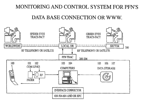
Figure 1
Is an illustration showing the monitoring and control system and a PFN
enclosure with its
characteristic conununication options, processor and computer capability and
its accountable data
storage systems, as well as, its electrical interface connector to connect
with a host machine. This is in
keeping with the same technology from the first application and the remainder
of the drawings will
display and describe more varied levels of capabilities and sophistication to
meet the present high
security requirements needed in special government.
Figure la
This figure is the software that provides a Trusted Activity Controller the
TRAC system of
software and software embedded hard ware or firmware and/or microprocessors
FACT chips
individually assigned and incorporated as identifying circuits and mini
processing centers to insure
accountable remote control tracking integrity as a system and for any and all
individually directed
activities no matter the origin of order and/or purpose.
TRAC a Trusted Remote Activity Controller has easy teclinical capability for
any and all of
humanity. However, all forms of human governance will have to be responsible
in determining how to
best use this accountable technology.
Figure 1A1
This figure is part of the progressive consolidation of the invenions
interfaced systems
integrated on a Chip to (SOC) technology.
Figure 2 (commercial high level security protocols)
The protected containment has many various different applications so specific
configurations
have been deliberately avoided. Therefore, this number two drawing of the high
security PFN' S wall
is shown as well as, how they will be altered to complete their specific tasks
for every application and
will be ultimately determined by a standards.
CA 02397911 2002-07-18
WO 01/54044 PCT/US01/01645
7
Figure 2A
This figure first appeared in earlier related patent applications for the use
of pagers the
primary communication technology and will be used in one and two-way
transmission application for
the least expensive communication means in PFNs in normal applications and
altered in wall structure
for higher security applications.
Figure 2B
This is an add-on system also appearing in an earlier related patent
application and its wall
structure will also vary as per application as detailed in figure 2. This
system utilizes wireless or
cellular phone service for its two-way communication medium
Figure 2C
This is another built in PFN system with its two-way and locking system
detailed in anotlier
earlier application for the automotive industry to organize all electrical
devices in a plug and play
system of drawers and compartments and displays numerous components and
devices. This system can
also have its physical wall structure customized for specific high security
applications.
Figure 2D
This drawing continues on to develop 2C on the interior of the dash PFN in a
mobile piece of
equipment. showing in greater detail some possible movement component and
device and this drawing
as well appeared in an earlier patent application.
Figure 2E
This figure shows three drawers which are a continuation of 2D as a possible
arrangement of
components for this multi interface system for electrical components.
Figure 2F
2F is the first of two figures showing a proprietary electronic heat seal
system to insure there
has been no tampering with the protected PFN are for legal evidence.
Figure 2G
This is the second drawing of the security seal and it describes how the seal
functions
Figure 3
Shows the two basic PFN communication categories which are being developed.
There will be
one-way transmission devices and there will be two-way transmission devices.
The drawing also
illustrates the monitoring and remote control system from the local level to
the global level. The figure
also shows all the qualities and peripherals as well as the security systems
for conditioning any two-
way signal transmissions.
CA 02397911 2002-07-18
WO 01/54044 PCT/US01/01645
8
Figure 3A
This is a self explanatory chart to show the accountable data storage for on
board in the PFN
and off board within the monitoring and remote control system. This chart can
be referred to when
reading and viewing figures 3-4-5 & 6 with all the different types of
communications detailed. The
chart will quickly provide the basic report back properties and data storage
systems to expect form an
individual PFN by the conununication service it is employing. However in many
cases a PFN might
interface a plurality of communication systems.
Figure 4
This drawing is of the simplest one-way communication PFN and these basic
electronics have
already been prototyped used and proven from and for the other related
applications. Basically with the
one-way communications systems data storage is on board the host in the PFN at
two separate
locations and require physical retrieval of the data. This device in its most
basic form will not report
back to any remote control and monitoring system, but can be sent messages,
which will activate
preprogrammed responses.
Figure 5
This an illustration of the simplest two-way communication systems and the
necessary security
devices to condition the signal with encryption for high security protocols.
It is basically another flow
chart showing the data from the remote control and monitoring network as well
as all the data and
control signals to the data storage and the peripherals through the many
possible processor options.
This is the same as figure 4, however it is in two directions with the remote
control and monitoring
system and there by creates three accountable levels of data storage on and
off the host piece of
equipment. Two levels on the equipment and at least one remotely stored copy
of any pertinent data.
Figure 6
Employs the most sophisticated high security two-way communication capable of
full real time
video with either cellular or digital phone or any radio frequency specially
delegated for these
purposes. These types of devices will carry all types of report data signals
and cost will be
proportionate to the level of sophistication and the hardware and software
required to support the
services desired by all accompanying peripheral devices.
Figure 6A
This drawing details how drawings 3, 4, 5, and 6 are merging the communication
technologies
with computers and memory as well as automated control systems and data
management and sensory
systems. And more specifically it details the growth and development of the
components and separate
devices into one set of secured accountable PFN circuits and provides for alI
the future commercial Off
The Shelf Products to be used in the PFN. With plug and play universality but
achieving the same
stated purpose as has been proposed for the invention all the time. Which is
to provide a secure
protected accountable electrical interface.
CA 02397911 2002-07-18
WO 01/54044 PCT/US01/01645
9
Figure 7
Depicts a security enclosure and in this case it illustrates a nuclear
scenario requiring unique
types of monitoring and remote control. This could be any security scenario
with different requirements
and specific peripherals with varied protected circuits, but with the same
need. To monitor and control
a restricted secure area with accountable remote control or robotics from
local, regional, and global
monitoring networked together and also in a secure manner.
Figure 8
Illustrates the many varied high security purposes of the installation secure
area system
depicted in figure 7. It shows some of the governmental uses, and commercial
applications for a secure
installation, that are hazardous and can be enhanced by unmanned operational
functions e.g. oil, gas
and chemical plants, medical waste and sewage facilities, nuclear substance
use, and nuclear waste
storage and a multitude of other science, energy technologies as well as
monetary processing either in
hard currency or credit - debit data.
Figure 9
Is a list of the allocated frequencies and their use and the agencies that use
them.
Figure 10
Is a continuation of the list of allocated frequencies from figure 9.
Figure 11
Is a more extensive detail of the TRAC software flow and the all the
application specific
programs running in the Trusted Remote Activity Controller.
Figure 11A
This figure expresses the Trusted Remote Activity Controller's properties and
qualities in
software and interfaces.
Figure 11B
Describes the hardware implementations.
Figure 11C
Is the Trusted Remote Control TRAC features that make it trusted and
essentially different and
unique as an operational management center and communication routing and
rerouting device
Figure 12
Shows a world view of all the communication linked PFNs and their application
specific uses
in normal everyday life,
Figure 13
This is a 27 page listing of all the national government agencies that are
supporting web pages
and this invention details how to hyperlink them into four public web account
pages utilizing the data
recovered from the PFN/TRAC system and processed for or by these agencies as
part of public
accountability and interaction with government and commercial interests.
CA 02397911 2002-07-18
WO 01/54044 PCT/US01/01645
Figure 14
This drawing further details the PFN applications and shows there uses in
every day
management applications
Figures 14A and B
Are two pages of charts and descriptions that were taken off the Internet
detailing The
International Standards Organization or (ISO) Reference Model. And with a
basic discussion in
reference to the Open System Interconnection or the (OSI) of networking
including the seven levels to
creating net work communications between computers and how FACT and the
Registry can operate.
Figure 14C
This power point figure sheet for the World Bank and International Monetary
Fund is
exemplary illustrate some of the economic and financial attributes of the
invention to the investment
industry and electronic payment and monitoring process by supplying accurate
real-time data to all
involved parties to best work out the proper management at all levels with the
best understanding
Figure 15
This drawing introduces FACT as individual chips that will be manufactured
into all electrical
components to track and control their authorized use and value that use.
Figure 16
This illustration details how the FACT chips work inside the PFN/TRAC system
to be an
accountable and well organized use of electrical devices on each and every
piece of equipment. The
individual chips in each component or device identifies the component to be
recognized by the
National registry after the initial data is processed by the PFN\TRAC\FACT
computer programming
when it is connected to the uni-buss either in the protected containment of a
PFN or some input output
port.
Figure 17
Is a further description of the FACT TRAC system that originates in the PFN
device and
pinpoints; interaction in any platform of communication to be identified as
legitimate electrical
technology that is rriade accountable in its manufacture or creation and
legitimate and accountable for
its use civily. Fig 17 details National Regional and Local Governmental
control and management and
the employment of the FACT system secondary failsafe check to insure
accountability of legitimate
product use.
Figure 18
Is a more detailed view of the devices interfaced to perform the Federal
Access Control
technology FACT. And Commercial Encrypted Web CEW technology to perform secure
and
accountable tasks through the three main communication mediums, of one and two-
way paging, wired
and wireless telephone technology and all forms and frequencies of radio
communication. This
drawing shows the Data Base Connection and the Internet use.
CA 02397911 2002-07-18
WO 01/54044 PCT/US01/01645
11
Figure 19
Shows the lines of interactive communications from the PFN all its sensory
inputs the
commercial servers and public provided nodes linked to local government state
and national
government and screened interfacing witli world organizations and the uses of
all types of
communication links to provide a secure accountable network..
Figure 20
Shows a base application of the software flow activities both at the PFN level
and in the main
registry and a typical interchange concerning the main purpose of a such an
accountable network,e.g.,
to reduce the crime of component, device and/or equipment theft, provide
greater National Security
through properly identified and qualified components being made accountable
for performing
automated and remote control activities for societies and their institutions.
And finally to provide
greater accountable public safety e.g. a fail safe capability by being able to
individually address
numerous similar functioned electrically inventoried devices as operational
through PFN management
devices to perform a task, e.g., Cell phone failure and a pager is interfaced
switch communication use
to the pager system to receive signal for an authorized remote command. Even a
standard car radio or
audio system interfaced through the PFN will be able to receive one-way
communications to perform
PASS, Proprietary Aggressive Slow Stop, and Securing of a piece of equipment.
Figure 21
This diagram is more descriptive of the software functions of management and
control
commands. It shows basic driver and/or owner notification functions and those
that could be
coinpleted without notification as per constitutional law to be written and
legislated extending court
order wire tap and phone taps being extended to use of this security function
in the PFN/TRAC system
and incorporated into FACT software protocols.
Figure 21A
This figure is a national Transportation Machine messaging Net work for the
invention the
PFN/TRAC System
Figure 21B
Is a further detailed figure for the national transportation system in 21A
functioning for local
control and traffic management down to the local traffic intersection level.
Figure 21C
This figure is a power point drawing highlighting the usefulness of the
invention the
PFN/TRAC Device and system for the Department of Transportation and also
illustrating the many
faceted advantages for this type of accountable remote control and traceable
communications for
mobile and stationary applications in remote control and robotics as well as
traceable communication
routing.
CA 02397911 2002-07-18
WO 01/54044 PCT/US01/01645
12
Figure 21D
This is a figure detailing the federal Communication Conunission s recently
Dedicated Short
Range Communications alloted to tomobile applications
Figure 21E
Is a diagram showing the PFN/TRAC repeating and or digi-peating capability
that can be used
for personal tracking and accountable remote control through all responding
units, or used to link any
and all systems of short range wireless communications and transmit a signal
or retransmit a signal or
transcribed message though other interfaced communication systems that are
responsive processors
Figure 22
Figure 22 is a diagram of the system that allows parolees back into society by
tracking their
movements. This system can be an isolated intranet and or communication system
or achieved tlirough
repeating or digit-peating through other PFN/TRAC units.
Figure 23
This power point diagram of the PFN/TRAC System points out the importance and
value to
the FCC the management locally and accountably for diverse frequencies and
their efficient use to
maximize the physical environmental paraineters for any particular and or
designated frequency in use
or to be used at any given time and process any and all electronic
communications or any propagated
digital communications and or any transmissions or retransmission of converted
messaging in the most
efficient and less noisy manner.
SUMMARY OF THE INVENTION
These innovations have been predicted and partially described in the earlier
applications. They
are the security protocols and are intended for the high security development
mentioned in the "Stop
and Control Box", Black Box, and Billing Boxes and their coinbined functions
that were described in
all the related patent applications as the secure and protected PRIMARY FOCAL
NODE or (PFN)
also wit11 all the possible computer networking including the Internet.
.Along with the varied PFN devices that will be attached to all equipment,
machines vehicles
and environmental sensors and devices is the evolved third embodiment of the
first application. A
flexible in size and capable monitoring and remote control system that can be
singular and local or
networked to any extent with all the variations of PFNs and other systems if
so desired through FACT
software and national and local connectable FACT registry. From the first
application of this invention
has prescribed a secure accountable remote control electronics package as it
is a major objective for
this technology . So it is only fitting that even the first commercialization
of the invention increase
security for life, society, government, business and industry; because of all
the basic accountable
features the invention can provide to any present security management and/or
control system. Some of
the enhancements are obvious in the areas of impregnable electronics, and also
the versatility in
CA 02397911 2002-07-18
WO 01/54044 PCT/US01/01645
13
providing levels of inexpensive remote-control for secure areas requiring
automation to replace and/or
reduce personnel at risk.
The invention provides for at least three levels of accountability in its most
sophisticated
functions, two on board and at least one in a remote location. The invention
has always claimed to
provide a secure physical environment for the electronic components and
devices, but in this
application the PFNs are specifically designed to protect any of their
transmitted signals by first
conditioning them by encryption, so only the authorized personnel and
terminals can decipher their
encryptions and gain access to the data. This security protocol is also
carried all the way though the
system and will therefore easily marry into any existing system, which
requires these same Protocols
DES and PGP, which stand for the government Data Encrypted Standard and the
commercial versions
Pretty Good Protection. However, PGP suppliers will be required to coordinate
and incorporate their
encryption with FACT software algorithms to provide for the Federal Access and
Control FACT
registry of component, devices and equipment, ultimate interdiction and
control when they are going to
perform aggressive remote atld automated control activities in a host machine.
(This is legal for the
automated equipment to be policed by society's automated policing systems.)
The monitoring and control systems for high security application will most
probably be closed
circuit with an individual set of government allocated frequencies, and
specialized hardware firmware
and software (Government \DES systems). However, with the software, and/or
commercial firewall
protection known as pretty good protection (PGP) inexpensive monitoring can be
provided in near real
time with only marginally diminished security in any direct PFN transmissions
to the World Wide
Web (WWW) phone node servers and their inexpensive gateways and/or any
networking from the
local computer terminal to a WWW server phone node. This option for many small
and medium
commercial operations will be provided more economical possibilities for their
semi-sensitive or less
secure needs to monitor current events at isolated installations globally in
any specific installation. If ,
through this casual monitoring, it was necessary to give a remote command to a
PFN controlled piece
of equipment based on the web image the remote control commands can be given
through regular
phone services and/or any other piivately owned and operated communication
system, that the PFN has
as a communication device on board for. This would allow for limited use of
expensive phone services
or commercial satellite communications for the long process of monitoring a
remote secure area and
only require the expensive communication technology to send short commands.
These monitoring
functions were described in the second patent for a community web page
monitoring of unrestricted
governmentally prepared PFN generated public information data streams. The
difference here is the
use of PGP and/or DES or any encryption to conditional a signal limiting
access to these types of data
streams whether they be commercially generated and altered or governmentally
controlled. The other
security measures are limited access to a web site or controlling access by
special identification
measures, e.g., pin numbers and synchronized timed personal access number
cards. Or the use of the
CA 02397911 2002-07-18
WO 01/54044 PCT/US01/01645
14
local control computer 300L to do the dial up and or act as a RF repeater
station for a local page
network of PFNs which would make the phone node connection to the web
(optionally automated).
This could be utilized in much the same manner as has been described in PCT
application No.
PCT/US99/00919 (202) for the separate government agencies that provide direct
phone node
equipment to their agency network as well.
However, this describes how the PFN can be first sold as a conunercial
product, but to
coordinate and use this technology on a massive basis the most important
development in this
application is to.use the PFN/TRAC/FACT Registry system in harmony with all
the PFNs and an entire
web that provides for individual PFN direct access to the registry and/or
though any and all isolated
systems that have their own gateway to function (but FACT licensed) through
the PFN\TRAC \FACT
system. (This development will be governed by legislated law, codes,
regulations and standards in the
future but for all intensive purposes will be detailed here and now so that
anyone can understand this
accountable management system and so those skilled in the arts could easily
construct it.)
As described in PCT/US99/00919 (202) and PCT/US99/13668 (302) for the spider
eyes
systems all the PFN activations require all the electronic serial numbers,
land line numbers and/or RF
ESNs from all communication links as well as personal ID verification, e.g.,
finger print, card swipe
and/or PIN numbers, or any synchronized personal ID time changing pin code
verification devices or
systems, etc. And along with this data is always the date and time for any
remote control command,
which is always accountably recorded with all the electronic serial and ID
numbers ECT as the
command string in the PFN any remote control contact. Also, any response
telemetry data generated
from the action to a remote command is recorded and stored for an application
specific time period and
then either entered into the permanent PFN record storage or delete for
space.' And any and all
installation PFNs that are working in concert (net worked together) to achieve
a remote control action
will also establish their telemetry records in the same manner providing a
multitude in many layers of
accountability header provided with the appropriate FACT, ESN, MIN, VIN or
necessary FACT
manufacture data and nay activity application data that is programmed into the
firmware or software.
This application details the quality and properties of the accountable modular
and
programmable software termed TRAC that authorizes and authenticates commands
from wireless and
land line telephone and/or RF equipment and/or light transmission technologies
to remotely activate
and confirm automated controls and functions through its PFN processors
controllers and/or
computers. As TRAC processes this data in a secure manner it stores it in a
protected storage on board
a piece of equipment in this technology's PFN on location and in the two-way
transmission PFNs it
reports back to at least one remote location to achieve at least a third
redundant memory storage. The
reality of the invention is proven in the feasibility prototypes of the
earlier related patent products.
However, the need for governmental and commercial collaboration is essential
to the entire FACT
system's Reality
CA 02397911 2002-07-18
WO 01/54044 PCT/US01/01645
This TRAC system was designed to distribute communicated commands to their
appropriate
application specific preprogrammed protocols, while authenticating the
authorizations and preserving
and accountable record on both sides of the remote control communication
scenario and through out
any redundant transmissions or data storage. The TRAC system of software has
been designed to
develop a Trusted Remote Activity Controller for all of societies needs
regarding accountability and
liability as well as to preserve and/organize secure modalities to manage and
control automated
equipment, and financial legal transactions.
With the advance in electronics, communications and computer processors the
automation of
equipment is rapidly approaching aggressive remote control and robotics and
needs to be made as
accountable as the owners and operators who have been solely responsible for
machine control in the
past. Because, control responsibility will be shared at first between man and
machine and might very
well always be this way; accurate telemetry of both will be essential to
provide organization and proper
management and legal control in this scenario. This technology's PFN protected
primary focal node
and The TRAC software system has been constructed to provide the means to
accomplish these control
and accountability tasks and to serve as an electrical interface, physical
platform, and software control
center to write standards too.
These are just some of the increased synergistic benefits added by the
invention's secure and
accountable remote control when made part of any existing security system. The
invention's security
uses are endless, because of the great inventory of possible COTS components,
and devices that can
be integrated and interfaced. The designed universal plug and play versatility
has been deliberately
developed to combine and work with all other pieces of equipment and systems
where ever possible.
This has always been another goal of the invention from its inception. To
provide a practical focal
point that is a universal physical platform to support a versatile electrical
interface for responsible
remote control for every piece of equipment, machine , vehicle and
environmental need to increase
public safety national security, to provide just and fair monetary exchange
and respect for each
individual in a society. Accountability for the use of equipment and Data
acquisition is the best way to
achieve and assure these things and it must be built right into the interface
and protected as well by
backed up remote traceable memories.
All the patent applications first combine all these present separate parts,
products and systems
as interfaced separate entities and in this application they are progressively
consolidated and
standardize the electrical interface and circuits of this protected physical
structure to the most concise
set of universal application specific controls in appropriately sized
physically protected containment
(known as a PFN).
Throughout this application all the security ramifications and uses will be
described in detail,
and with the related applications incorporated herein by reference the list of
possibilities is not only
endless and feasible, but also practical and a necessary direction for future
security scenarios for all
CA 02397911 2002-07-18
WO 01/54044 PCT/US01/01645
16
aggressive remote controL This application combines security technology with
machine
communication to create commercial automated and remote control with an ideal
organizational
platform to set standards for society in general and all the regulating
government bodies FCC, FAA,
DOD, DOT, FBI, CIA, NSC, and various professional organizations IEEE, Fire and
Alarm industry,
insurance industry and on and on.
At no time does the invention in any particular field attempt to set standards
or criterion for
any specific technological applications or use. But the invention address
almost all responsible
modalities and/or issues in a clear and evident manner to practically achieve
all the claims of this
invention. The invention only seeks to provide the present world's
technologies a set of more universal
secure accountable electrical interfaces of physical platforms for remote
control and robotics, which
are designed to provide accurate information and control options reflective of
human needs with
present and future machine interaction . With this accomplished hopefully this
will improve the
likelihood and chance that logical common sense and scientific decisions by
societies, their commercial
interests, and their authorities can be aided in making the best choices for
the world's populous to
secure peace, tranquillity, as well as, develop a healthy respect for one
another, and maintain a safe
environment in a timely manner with as little unnecessary disrespect,
disruption , deprivations,
destruction and death. Ideally individual freedom will be guaranteed by a
developed social respect for
the individual secured by accountability, because most certainly personal
privacy is going to continue
to be reduced by all of these developing data acquisition technologies, which
also have the potential to
provide a better quality of life in general for the whole of humanity. This is
an important issue and
always will be.
The invention has been designed to provide humanity with the tools and
capability to provide
secure organization and informational data for this most natural and
appropriate human knowledge
quest and assist in obtaining an optimal growth in these directions for
humanity's development, while
maintaining fairness and/order for all individuals to develop in their
individual existence in using these
extended freedoms and tools responsibly and respectfully und pain of the law
for any misconduct. But
this invention's implementation and any society's use of the invention is and
always will be in their
hands and have to be responsibly shouldered by all of the individuals of any
society that uses it.
Detailed Description of the Drawings
FIGURE 1
Figure 1 is an illustration showing the monitoring and control system and a
PFN enclosure
with its characteristic communication options, processor and computer
capability and its accountable
data storage systems as well as, its electrical interface connector to connect
with a host machine. This
is in keeping with the same technology from the first patent application and
the remainder of the
drawings will display and describe more varied levels of capabilities and
sophistication to meet the
CA 02397911 2002-07-18
WO 01/54044 PCT/US01/01645
17
present high security requirements needed in special government and commercial
applications. FACT
is introduced as the Federal Access and Control Technology that will be
running in all remote control
capable systems governmental and civilian. It is an encrypted operational data
system software that will
allow for accountable access to all such systems and under proper court
authorization allow for
undetectable monitoring and control of any and all equipment. Fact processor
chips will be in all
responsive connectable components for remote control as well as in expensive
electronics to keep track
of their legal and illegal use through and by any PFN system running TRAC/FACT
software. TRAC
stands for Trusted Remote Activity Controller and is the base operating
software system operating in
all PFNs.
First however, is the base hardware components and systems running these
programs of which
TRAC & FACT are only two of tliem. The components in figure one as numbered
are as follows.
Number 300 shows all three levels of a possible network of off board
coinputers in which the local
computer is the standard gate way, but not the only control terminal and it is
not a necessity that the
control communications even go through the local terminal. With the use of
cellular phone technology,
RF signals, and paging devices as the receivers and transmitters, signals can
be sent from any terminal
if so desired. (e.g. emergency situations ). And also by employing the
equipment identification system
(ESNVIN) and or (ESN SN) or MIN protocols and personal ID devices properties
and qualities
detailed in all the earlier related patent application for the spider eyes
program, coupled with the on
board data storage devices numbered 105-106-107 in this drawing. And the off
board report back data
storage; provide total accountability for remote control activity which can be
established through the
entire system from all of the off board monitoring and control systeins to
each individual peripheral
system attached to a PFN numbered 200-204 in this number one drawing and most
especially with the
incorporation of TRAC and FACT soft ware programs. The multi numbering is for
the different styles
of security and protective packaging of PFNs and data storage devices and
systems, which are all
detailed in great length in the earlier related filings.
100 is a wireless phone, either cellular, digital satellite or even cordless
either as represented as a hand
held COTS device that has an interface modem and/or cable to connect it up
with one of the five
computers detailed in the preceding related application or as an IC chip set
integrated circuit and or
interfaced with any of the onboard processors, programmable controllers or
computer boards either by
edge connectors or direct hard wiring or IEEE couplers. And 100 can also be
PCMCIA card or
"Complete Card" TM Cell phone card with antenna. (This system will be first
utilized in all prototypes
including high security.
101 is the standard time honored pager in this drawing showing only the
reception capability
of the standard COTS pager. This is done to accent that there is a real cost
effective use for one-way
paging in high security applications as will be completely described within
this application. However,
also in this document it will be equally illustrated that the new reflex
paging protocols of Motorola can
CA 02397911 2002-07-18
WO 01/54044 PCT/US01/01645
18
also serve inexpensively and offer limited two-way communication capabilities.
The first related
application totally details many different modalities to utilize the standard
paging devices and is
incorporated herein by reference. However, also through out all the related
applications the
incorporation of COTS paging IC. chip sets accompanying circuits and software
protocols have been
incorporated into PFN consolidation of circuitry and size, as referenced by
the design use of
Motorola's Create-a Link TM combining communication and processing, in some
limited switching
functions in the protected accountable PFN system.
102 is any other RF frequency that can be used to send and/or receive either a
guarded or
unguarded signal. to a PFN device. And the following frequencies are listed in
an Allocation table as
figures 9 and 10 of this application as they are known today. The list is in
no way to be considered the
only frequencies that this invention claims and in fact any and all wireless
communications and hard
wired communications are claimed to fall within the nature and scope of the
invention when they are
used in an accountable and/or protected interface for remote control.
103 refers to the proprietary Parallax computers stamp I and stamp II and 104
refers to all five
of the 100 Euro-board mini computers named in the preceding application with
their varying degrees of
capabilities. And also in this formal application there will be a complete set
of drawings detailing the
prototypes to make them more resistant to EMFs and other damage from radiation
for the high security
and hazardous or hostile environments.
105 -106-107 is the on board data storage components of the PFN. However,
there is only 2
levels of memory or data storage generally planned for in the PFN. One is a re-
writeable memory
recording predefined data unique to equipment and or personnel. The second is
priority data which is
stored in a non- volatile and protected memory (determined by application
specific protocols). And
number 108 up in the 300 block of computers networked together illustrates at
least one remote storage
out of the PFN. And this will be a redundant storage of the same application
specific protocol data
stored permanently on board. This provides three last minute comparable
records which are all timed
and dated for analysis and accountability. The number 105 generally refers to
embedded hardware,
firmware , EEprom, and/or flash memories and 106 refers to hard drives and 107
to writeable CD and
MO disks as detailed in the earlier applications . These can be part of a
integrated or interfaced circuit
with any of the processors and/or mini computers and/or stand as separate
components interfaced
through hard wires and/or physical connectors, which also has been thoroughly
detailed in the earlier
applications. Anyone of these data storage components can function as re-
writeable data storage or as
permanent storage.
108 is the off board storage and it is also detailed in earlier applications
but it is safe to say that
all data stored for these high security applications will have specific
systems and protocols to manage
any stored data. TRACS and FACT will be detailed through out this patent
application as an exemplary
software protocol for handling this data on and off the board.
CA 02397911 2002-07-18
WO 01/54044 PCT/US01/01645
19
FIGURE 1A
This figure describes the Trusted Remote Activity Controller TRAC, which is
the basic
operating system to provide accountability. It also calls for two
standardization efforts for internal
communication and external communication, for universal connectability which
will be elaborated in
much more detail in Figures 6A ,17 and 19 Trusted Remote Activity Controller
(TRAC ).
OPERATION
The Trusted Remote Activity Controller provides all local vehicle or device
control and event
storage relative to PFN (Primary Focal Node) operation. It interfaces to any
RF telemetry link, which
may consist of a one or two-way paging system. More sophisticated links could
be used such as
digital cellular or PCS (Personal Communication System). Typically, a Remote
Management System
(which may be as simple as a single page, or as complex as a controlling PC or
Server) initiates a
TRAC function, such as an automated slow, stop and secure sequence or involves
robotics including
guidance systems more and varied speed control and/or any accountable
aggressive remote and
automated function.
The signal or paging command is received securely via encryption) and decoded
by the TRAC.
Optionally, a local display or audio speaker may provide local status of the
TRAC function being
executed, with appropriate progress tones, voice queues or displays to provide
a local operator
feedback relative to the progress of the function.
In performing the function, all activity controls are initiated by the TRAC
and monitored by
the TRAC from start to finish. This is accomplished through feedback sensors.
Feedback Sensors may
be electrical, mechanical, fiber optic, infra red or other technologies. Since
the function being
performed requires a high level of accountability and trust that the sequence
was in fact executed
properly, every step of the process is monitored through appropriate feedback
sensors to attain the
reliability and trust required. This positive feedback in the TRAC is the key
feature which
distinguishes the TRAC from other electronic or software controllers; making
it a fully "trusted"
system for the task being accomplished.
Additionally, all events and status relative to the function are recorded
locally in the Local
Event Storage Memory. This is termed the System Function Data. The level of
redundancy in storage
of System Function Data and the level of additional feedback and checking
required in order to verify
the Activity or function was accomplished properly, is directly related to
verification requirements.
These requirements may be regulated and approved by local or federal law, law
enforcement or
insurance agencies, World Bank, EPA, ICC, SEC or other regulatory agencies.
Interim progress of the sequence, activity or function may be optionally
transmitted back to the
remote management system through a 2-way phone or paging link. This may occur
as the function is
executing or may be programmed to occur after completion of the sequence. In
any event, local,
CA 02397911 2002-07-18
WO 01/54044 PCT/USO1/01645
redundant storage of the event is always contained within the PFN for
subsequent or simultaneous
retrieval of event information and proof for accountability purposes. The PFN
enclosure and TRAC
monitoring of tamper sensors guarantee the information has not been
compromised. Also unique
sealing systems further provide tamper detection. Other types of information
along with the System
Function Data may be stored in the TRAC Local Event Storage Memory.. This
auxiliary information
may include digital or analog data not directly related to the function being
monitored and executed,
but important for evaluation and determination of liability, collection of
evidence or environmental
data. Examples of these include road condition information or surveillance
audio and/or video.
IMPLEMENTATION TRAC implementation may be accomplished in many ways, depending
on
space or funding constraints and level of integration required for the system.
A PC based system may
be in the form of a desktop system, laptop or embedded system (PC 104) with a
dedicated DOS or
Windows based TRAC program, consisting of machine language, Basic, C, C++,
Visual Basic, Visual
C or C++, or other high level language which accomplishes the TRAC function
through software
control.
Interfaces to the System Under Control (SUC) may be accomplished through
appropriate I/O
cards, either analog or digital. PC compatible Modems or Cell phone interfaces
provide the interface
to the Remote Management System (RMS). SUC and RMS interfaces may be in the
form of ISA, PCI,
PCMCIA, VME, Compact PCI, Future Buss, or other commercial interfaces
compatible with the PC-
based system used by present technology.
More compact and custom implementations of the TRAC may consist of dedicated
state
machine controller implementations in which TRAC functions are executed
through embedded
firmware. These implementations may incoiporate multi-chip solutions using
EPROM or EEPROM
interfaced to Arithmetic Logic Units (ALU),1/O ports and discrete memory
elements a basis for FACT
Federal Access and Control Technology where microprocessor and'ever expanding
memory circuits
and devices are emerging. They may also be microprocessor or microcomputer
based. A large variety
of board level products are commercially available for such an implementation.
Single chip or high
density implementations might consist of Field Programmable Gate Array (FPGA)
or Application
Specific Integrated Circuit (ASIC) based devices.
These implementations may incorporate all sequencer, firmware, UO and storage
functions on
a single device and would provide the highest level of integration and
smallest size. Display, Video
and Audio (Auxiliary Data) for the TRAC can be in many forms and types. These
may range from
analog systems, in which tape or other magnetic media store the analog signal,
to digital systems in
which data is stored on hard disks, EEPROM or RAM. Data format may be
modulated through FM or
AM, compressed, packetized or otherwise encoded for reduced bandwidth or for
transmission over the
Internet (packet audio and video). And even modulated over power connectors to
save space and
individual material component use.
CA 02397911 2002-07-18
WO 01/54044 PCT/US01/01645
21
This block diagram shows the PFN/TRAC systems interface of green vehicle
controls and
sensors on the left of the red TRAC module (e.g. is Systems On a Chip or SOC);
It additionally
includes, the remote wireless connections and extensive machine messaging
network of IP protocols in
blue on the right. The Diagram also indicates in vertical rectangles of dotted
lines, two primary
standardization areas. The one on the left requires a standard universal bus
for the system under control
requiring DOT, Vehicle manufacturers, CEMA, ITSA, and SAE at the very least.
The one on the light
requires a standards effort for all wireless communication applications.
Without question, this will
involve other government agencies and organizations including FCC, ITSA, CEMA,
SAE and many
other government agencies and organizations. Additionally, these standards
efforts have to be
coordinated with a third standards effort. The focus or aim being to set
program parameters qualities
and properties for an accountable mindful machine control center e.g. PFN/TRAC
unit. Once again
much of these questions and issues are covered in the writings for the
PFN/TRAC System, but this is
an area where government must lead. Most all industry is specialized and
commercially alienated from
each other. Due to the need to address specific market competition, many
manufacturers can not
adequately research how their products interact in different environments.
PFN/TRAC was created as
an organizational management tool so that these specific manufacturers can do
what they do best in a
more harmonious, accountable, and publicly safe way.
Figure 1A is a flow diagram that performs remote and automated controlled
functions and also
authenticate their performance. It is also a precursor or base operational
system to operate more
controlling management system in a socially responsible and accountable
manner.
In this patent application the major issues of freedom and privacy will be
legally addressed with
humanity's need for civil control and all will be held accountable.
FIGURE IA1
This block diagram shows the PFN/TRAC systems interface of vehicle controls
and sensors on
the left of the center TRAC module (e.g. is Systems On a Chip or SOC); It
additionally includes, the
remote wireless connections and extensive machine messaging network of IP
protocols on the right.
The Diagram also indicates in vertical rectangles of dotted lines, two primary
standardization areas.
The one on the left requires a standard universal bus for the system under
control requiring DOT,
Vehicle manufacturers, CEMA, ITSA, and SAE at the very least. The one on the
right requires a
standards effort for all wireless communication applications. Without
question, this will involve other
government agencies and organizations including FCC, ITSA, CEMA, SAE and many
other
government agencies and organizations. Additionally, these standards efforts
have to be coordinated
with a third standards effort. The focus or aim being to set program
parameters qualities and properties
for an accountable mindful machine control center e.g. PFN/TRAC unit. Once
again much of these
questions and issues are covered in the writings for the PFN/TRAC System, but
this is an area where
government must lead. Most all industry is specialized and commercially
alienated from each other.
CA 02397911 2002-07-18
WO 01/54044 PCT/US01/01645
22
Due to the need to address specific market competition, many manufacturers can
not adequately
research how their products interact in different environments. PFN/TRAC was
created as an
organizational management tool so that these specific manufacturers can do
what they do best in a
more harmonious, accountable, and publicly safe way.
FIGURE 2
It is important to remember that any structure designed to protect the
electronic integrity of any
interface and performs the described functions of a PFN as well as, provides
protection for any of its
essential peripherals to increase performance, longevity, durability or to
increase reliable service,
and/or to better perform accountable remote control like protecting a system
like the PFN/TRAC
system in any environment or from tampering fall within the nature and scope
of this invention and all
of the above related filings. This is and always has been a major attribute of
this technology. To be
eitller universally, and/or generally and/or specifically construct for the
purpose of protection against
any rough service environments and/or vandalism or tampering. (The
demonstrator prototypes for high
security will also have detailed drawings in this formal filing that will
basically divide this technology
into two product lines of capabilities determined by the type of communication
technologies employed.
They will be either one or two-way transmission capable. However, they may or
may not both use the
same containment structures or provide both forms of communication if so
desired. They will once
again utilize pager technologies, cellular phone technologies, and/or any
other RF systems, as well as,
light communications either independently or in combination, as has always
been maintained
throughout all of the related filings.) The only other governing factors will
be the requirements of the
host equipinent, the desired functions or capabilities, and its operational
environment. It is these
considerations that will determine the physical protective characteristics and
configuration of any
specific PFN.
The other related patents incorporated herein by reference already detail
pager and a cell phone
PFN s for other commercial industries with less secure requirements. So many
of the same innovations
and devices will be employed in these high security protocols. Another
exception is the detailed
described development of greater signal security not just through physical
protection of the PFN and
peripherals , but also, accompanied by special electrical hardware, firmware
and/or software
TRAOFACT that will handle encrypted conditioned signals generated from a PFN
or to a PFN if need
be. Also, in this formal application certain other circuits and/or electrical
components will be
specifically designed and/or chosen, because they operate well in high
electromagnetic fields (EMF s)
and/or electromagnetic waves EMW environments and/or radioactive environments.
This will also be
the case for many other hazardous or hostile environments (Application
specific physical and
electrical structuring of the PFN.)
In Figure 2 only the wall structure is discussed at this time as it will be
constructed for specific
applications. Ideally the wall will be constructed as a laminated or composite
structure for the most cost
CA 02397911 2002-07-18
WO 01/54044 PCT/USO1/01645
23
effective manufacturing, however, in the very specific security applications
these wall components
might well require specific customization and because of their limited markets
increase the cost of a
PFN. Ideally universal structures will be standardized in application specific
areas to keep cost at a
minimum.
200 is the thermal insulating center lamination between two walls, the outer
201 and the inner
202. This center as already detailed in earlier filings and can or will be
composed of either fiber glass
products, gypsum, fire gels (from diapers), solid smoke silica, mica,
asbestos, or asbestos replacement
products , Teflon and/or high temperature plastics e.g. polysulphone, all of
which would either be
adhered to 201 and 202 or merely sandwiched between the two walls. However,
one product has been
chosen for the experimental prototypes, and it is called "solid smoke" and is
a product developed by
NASA for the space tile replacement and is completely detailed in an earlier
application.
Due to this center area 200 being a somewhat flexible fill insulation area
between generally
two solid structures a wire screen mesh, net, grid, or grill of metal properly
spaced and constructed
from metal products possibly copper, lead, etc. will be placed to block even
more EMF \ EMW and/or
various forms of radiation in special nuclear applications etc. To achieve an
additional radiation
screen. The mesh can be pressed or impregnated into this insulating composite
section in the center of
these two walls to add greater protection for the electronic products housed
inside the PFN. This center
can and will be designed to provide a soft seal when mated with another
section of a PFN wall that will
be resistant to the normal elements and harsh chemicals when end sections of
201 s are butted up to
other 201s end edge sections e.g. corners (the same for 202s) to provide
another surface to seal upon,
e.g., welding, resins, glues.
Manufacturing can also reduce cost by making three concentric boxes or
containers of any
application specific PFN shape,. One the largest out of 201 s outer wall, 200s
the second insulating
section and the third and final inner wall box out of two sides front and back
of 202s. A non flammable
glue adhesive or solvent for the insulation section would be applied to the
center section and the larger
201 box would have its inner surface chemically etched or conditioned to
receive the pliable adhesive.
And the outer surface of box 202 on the smallest box would have its surface
prepared in the same way
to receive the adhesive (if the surfaces are metal products). The protected
cable access hole will be
positioned to allow the trapped air to escape upon assembly of all three box
sections. This leaves only
one side to be installed with mating beveled edges which are both glued and
sealed, e.g., welded. This
last side or plate will contain the access panel with locking mechanism and
hardware (physically and/or
electrically controlled in most cases with special seals). And special
consideration is given to any
antenna and locking mechanism that is part of this protected containment with
hard wiring routed with
in the structure (these considerations are application specific with a lot of
details in earlier filings)
Three such earlier drawings with scaled back walls are detailed in figures 2A,
2b, 2c,2d, and 2e.
Figures 2 f and 2 g detail a special security seal around an access door.
CA 02397911 2002-07-18
WO 01/54044 PCT/US01/01645
24
201 points directly to the outer wall and this wall will be made of hardened
metal products
(described within) that resists physical penetration as a primary
consideration. It also could be coated
and/or covered on either side, and/or even be replaced by a penetration
resistant plastic like Kevlar or
other projectile and sharps resistant plastics Teflon, nylon and, vinyl etc.
(especially when the PFN is
employed in exposed electrical service application with high current. This
evolution of the outer wall
is in keeping with all the earlier designs and claims to provide PFNs to all
equipment and environments
as continually claimed in all the related patents. However, this exterior wall
in some applications will
be constructed out of stainless steel and/or coated with coirosion resistant
coatings or made out of
plastic and given special textures or wire webs, grids or gri11s. that can
also help trap EMF/EMW
waves and/or radiation so as to block their penetration into the electronics
housed within the PFN
and/or any peripherals, if so determined by an application to require this
type of protection. Once again
any and all of these technical variations can be employed, with the
consideration of the tradeoffs .
Which are almost certainly to be cost vs. desired and/or necessary practical
protection.
Through this entire description it is important to remember that any and all
of these protective
innovations may be employed, but final products will be constructed
application specific and in the
most cost effective manner for obvious conunercial uses and reasons. An effort
will always be made to
create the greatest security for the lowest cost, however, the more secure,
diverse and specifically
sophisticated the unit and system is the greater the cost will be for any
single PFN and/or the
peripheral system.
202 is the inner wall which can and will be constructed of various different
materials as
already named in the last outer wall description_ if so determined necessary
by application specific
criterion_for any specific PFN application. It may as well be constructed of
hardened steel thermally
tempered to increase carbon content in the molecular bonds or a metal alloy
composite product may be
utilized with, titanium, tungsten depleted uranium etc.(this is the same for
all hardened metal
applications for the outer wall as well). The inner wall could also be
completely constructed of solid
lead to create a final protective inner seal against radiation . Or a
composite plastic already listed for
the 200 and 201 parts with a EMF/EMW wave and radiation screen as already
described for 200 and/or
201 parts. Once again these could all be used in a laminate of layers or any
one could be singled out for
application specific priority to control cost. There are also recommended
protective handling
specifications put out by the federal government and industry for the best
modalities to deal with and
handle hazardous materials e.g radioactive, chemical, bio and medical waste,
EMFs high electrical
currents, etc. All the materials used and the manner in which they are used
will be developed for the
PFN prototype construction with full consideration and compliance with these
recommendations and
regulations to insure that this technology will be in line with any standard
set for any application.
203 shows the thickness of the entire wall, which is once again application
specific and will
vary as a general rule , but also as a general rule the different PFNS will be
designed to be as universal
CA 02397911 2002-07-18
WO 01/54044 PCT/US01/01645
as possible in shape, size and structural composition. The individual walls
201 and 202 may vary in
thickness as well as the necessary thickness of insulation. All of these
considerations will be
application specific. For example in the automobile industry and normal
civilian use the protective
structuring can be scaled back to a standard that does not require the kind of
protections detailed for
high security to meet an acceptable standard. This will be true for all
applications. They will
individually have to be structured to meet the requirements of the
application.
204 points out that the PFN will also be structured to be actually part of the
host equipment
physical structure in some security scenarios and in this case the system
would have to be secluded and
require limited and/or controlled access if it were to have the appropriate
military value. It would be
structured to assert final control over a piece of equipment but its influence
would be undetectable
and/or camouflaged to a large extent and above all extremely difficult to
access or terminate. (these
systems are reserved for special disclosure and development)
However, in many cases the PFN will be used to house and protect the host
programmable
controller (HPC) in the drawings 4-5-6 next to the mini computer contained in
the PFN. These
functions will ultimately in many cases be integrated with the obvious
advantage being consolidation
of the vital functional controls of the equipment integrated with partial or
the whole data storage,
remote control technology with the necessary security components all in 'one
secure spot in a plug and
play modular or card form and operated by TRAC software. Which can be
physically displaced for an
immediate disablement and total secured piece of equipment if-so desired. But
only by authorized and
authenticated entry if this is a feature or capability so desired. Of course
any portion of these
electrical components can be given this same plug and play capability if so
desired. Because this
Protected PFN\TRAC system & structure which is a protected physical electrical
interface center of
such wide base use and application ranging from high security, hazardous
environments and military
applications to standard civilian use a third standards effort will also be
necessary involving agencies
like NEMA, DOT, DOD, Higliway Safety, and professional organizations like
CEMA, ITS, and
manufactures to decide on the application specific PFN containment wall
structures that will be
manufactured and/or added to any and all equipment to provide legal physically
protected areas to
monitor, authenticate, record and perform remote control for each of the
varied applications. All the
base components elements and their properties and qualities are addressed in
this application and the
related applications. And as is true with all the components in the PFNs the
PFNs them selves can be
also exchanged to meet either more or less demanding environmental and
application demands; e.g.,
The government purchases a standard automobile that is going to be used in a
high security installation
or hostile environment like an Embassy. In this case the PFN structure will be
explosion proof
containment and un-penetrable by projectiles and EMFs etc.
CA 02397911 2002-07-18
WO 01/54044 PCT/USO1/01645
26
FIGURE 2A
It is a figure from the original patent and it illustrates a one-way pager
PFN\TRAC
containment with its protective encasement. Because there is a need for many
cost effective receiving
devices for the MMN. This one-way pager system was created to perform the
local accountability
proprietary vehicle shutdown PASS as a cost effective modality to be added on
to cars to aid law
enforcement end high speed chases. However this system can be used to remotely
control in an
accountable manner a piece of equipment when connected up to the appropriate
activity controls that
either interface electrically or perform push\ pull and/or rotational
operations to control virtually every
piece of equipment through automated and remote control.
2A01 is a manual lock for the PFN and these can be at any quality desired. It
also has an
electrical connection to be use in arming the device. 2A02 is the memory
storage in this case audio
recordings and a flash memory of operational data (Sony's memory stick 8
megabytes a piece). 2A03 is
using a stamp processor as the controller. 2A05 is employing OCR systems
however Motorola has
many COTS products that can hook up with direct connections and all are
covered in the related
patents. In fact this entire system has been well detailed in all the related
patents. Originally this
drawing appeared in the PCT/US97/121516, and in that PCT application the wall
structure was
described as one solid plate of Abrasion Resistant steel. This was being used
only for the puipose of
restricting unauthorized access to the protective interface compartment for
the unique purpose to slow
stop and secure a vehicle in real time. However in this application the space
between the lines of the
wall structure I am redefining to represent any necessary variation of the
double wall structure as
detailed in figure 2. Also the manual locking system could have the special
thermal plastic seal in
applications requiring this type of security measure for societies
institutions to authenticate its
functions and records. And finally this PFN containment for the COTS Pager
could be constructed for
any COTS RF equipment receiver and/or transceiver and/or wireless phones,
e.g., cellular, analog,
digital, cordless etc. and/or constructed to protect any interfaced integrated
system that comprises
communications/modems/ locating equipment/processors/memory/critical
connections/emergency or
supplemental power source.
Figure 2B
Displays two variations on the billing box accrediting system and the credit
card devices and
phone devices that have been innovated for these purposes. Primarily the
billing box was designed to
be an add on unit or after market device to collect a fee for use of a
vehicle, e.g. rental cars, taxi cabs,
buses, etc. Part 2B01 is either a standard credit card, ID card or any other
information card that one
wishes to use to enter information to the billing box (PFN). However with the
price of the smart cards
being greatly reduced; this device is not just designed for the regular
magnetic strip cards as has been
described earlier, but is designed to stay current with the more sophisticated
cards, as well as evolve
with other recognition systems e.g. finger print and voice and pupil
identification systems. Of course
CA 02397911 2002-07-18
WO 01/54044 PCT/US01/01645
27
the data retrieved from these magnetic cards can be recorded on board in the
billing PFN as well as
transmitted back to any network gate way computer communication terminal that
can make the
necessary land line connection to any credit check procedure and mass banking
management storage
for accounting purposes and records. And when this is done through a Billing
box or PFN and TRAC
system it is a commercial service product of the invention. TRAC can ran the
Bank card/Stock
Exchange Transaction products and algorithms via the commercial 128/64 bit
Encryption or web
transaction products . And/or utilize the COTS banking products and protocols
like NCR systems for
ATMs. These transactions will be provided memory storage for personal
accounting and verification to
the financial institutions as proof of payment. PFNs will be every where and
all those with ID systems
PIN number and key pads, finger prints and other forms of personal
identifications will allow for any
personal payment, authentication, and/or verification of transaction virtually
anywhere.
Part 2B02 is a cell phone handset configured with a forced card reader slot
and sensing head to
accept the card in the track or slot and extract the stored card data on the
magnetic strip to produce an
electrical signal that pro'vides encrypted encoded data to a converter circuit
that has a processor chip
with a firmware algorithm that can compare and prepare the data into
discernible language equivalents.
Or after the card reader prepares a signal, one of the PFN mini computers will
process the signal and/or
encrypted and encoded data through software programs running in the TRAC
software e.g. CEW
Commercial Economic Web transaction products either proprietary, Governmental,
and/or
Commercial Off the Shelf products either past and/or present or any newly
developed algorithm with
higher secuiity. With the use of the cell phone handset configured with the
card reader and slot the
lower bill box could be configured witli out a key pad. It would be possible
to use the phone hand set
key pad to give pin code and/or input data to the PFN box for the most
rudimentary communications.
Part 2B03 is a standard key pad that can be used to communicate with the bill
box when connected and
interfaced with any the invention's computer and supported with the proper
interfaces and software
and/or firm ware. Part 2B04 is a multi-bus bar connector universal with 29
contacts so that it can
support any system/device entered into the bill box. These were earlier
designs. And this earlier design
will probably not be used and will be replace by the multi bus system IEEE1394
or the universal bus
and/or any IrDA interface. Or completely replaced by the universal plug and
play uni- bus as described
with its essential properties and qualities in this application and all
earlier related patent applications no
matter what transmission medium is utilized to complete the tasks. So these
earlier mentioned COTS
connectable systems converters and/or interface circuitry will always be
relevant; because the base
PFN/TRAC system or the invention is designed to provide forward, backward and
present engineering
to be a complete universal plug and play physically protected accountable
interface that provides
accountability to real time remote and automated control and management
functions, for all vehicles,
equipment and machinery.
In the past and present Part 2B05 represents a quick connect end on one
portion that will
CA 02397911 2002-07-18
WO 01/54044 PCT/US01/01645
28
make a pigtail to connect witll any combination of electrical connectors on
the other end of this second
portion, e.g., computers, any electronic connections, radio or automobile. But
in this case it is depicted
in the drawing as e.g. RS232 part number 2B06. The other short pigtail is part
number 2B05, of which
there may be 5 to 10 in quantity or more, that can easily slide back and forth
to allow many varied
positions for the different devices and the space they require.
As mentioned earlier, hardware connections could be made with Commercial Off
the Shelf
devices in the box or by infrared com-port connections and/or a new and unique
total plug and play
uni-bus interface, that will be detailed in this patent application as to
quality and properties and
elaborated on as to the most favorable modality but will ultimately be
designated and prescribed
physically by a standardization effort involving government, commercial
interests and public and
private organizations. However this universal interface capability has always
been part of this invention
from the first patent application in 1996. The invention has always called for
a Protected electrical
interface of controls, communications, processors, with accountable records to
provide an
organizational platform for all electronics on a host piece of equipment.
Basically, the PFN\TRAC
system is this control center interface with total accountability for any and
all electronics on a host
piece of equipment, whether it would be a vehicle, a piece of stationary
equipment or any machinery,
and/or an environmental sensing system, which would and/or could provide the
appropriate data to any
and all in the appropriate manner to develop public trust, while
simultaneously protecting individual
anonymity and/or privacy in an accountable responsible manner with and through
the qualified
appropriate authorities in such a manner, that the legitimate legal tort
system could illustrate and use
this properly gathered accountable evidence of any and all real-time
activities to either properly defend
or prosecute on an incident and/or individual as fairly and respectfully as
possible and needed.
Another uni-bus system described earlier is the segmented infrared bar that
can be aligned to
any device's infrared window to communicate with the invention's control
circuits. Also there are
varied but designated power connections to supply power to any device by
priority. Once again most
all devices presently will be configured to IEEE1394 USB connections and have
their drivers and
software supplied by the manufactures to quickly install almost any desired
system as easy as buying a
product peripheral for a personal computer. This is one of the main reasons
for the timely presentation
of the invention.
After the devices are installed and connected, foam pad shims are placed
between the different
devices to quickly secure them in a protected stationary position. The dotted
lines show adjustable bin
space for the user to plan their own devices. Part 2B07 is a mouse ball that
one can use to run window
type graphic programs either displayed in the unit display 2B08 and/or any
larger display within the
field of view for the driver, either LCD vacuum tubes e.g. VGA flat screen, or
the new hologram wind
screen in the newer cars (e.g., Pontiac Grand Prix). Part 2B08 is the unit
display, part 2B09 is an
emergency power pack, and part 2B 10 is the secure bill box. The structure of
the box has been
CA 02397911 2002-07-18
WO 01/54044 PCT/US01/01645
29
described in the best mode of carrying out the invention in all related patent
applications. As to any
specific wall structure and insulated characteristics and modalities will be
modified and/or configured
in many different shapes and sizes as are deemed necessary and appropriate,
and are already
exemplified and detailed through the extreme variations in all the related
patent applications. However,
as stated earlier the third standardization effort called for and detailed is
for the physical protected
structures of these PFN/TRAC electrical connecting interface /system. Meaning
all boxes, coverings,
enclosures. protected couplings, specialized signal converting circuits that
are clearly developments of
the invention , which are all utilized in the secure PFN electrical
organizational platform.
This particular device (the invention) has been designed specifically to be an
accountable
interface for electrical communications to perform robotics, and/or aggressive
remote control; and to
provide accurate and responsible data both in anonymous and accountable
formats for the public in
real time through Intei-tiet links and web pages as part of a massive Machine
Messaging Network
(MMN) which through the PFN phone,RF and paging Gateway nodes connect with the
(WWW)
either through private networks or commercial networks , public or private web
page gateways (big or
small) to web as Internet providers and commercial servers.
This figure was originally drawn for the Cab industiy and is designed to be an
add-on device
for older equipment. Any of the PFNs can be configured to handle CEW
Commercial Encryption on
the Web , which in many cases will be provided by the bank card companies and
the payment industry
as their COTS payment industry products to conduct business through the PFN\
TRAC software
hardware as a CEW application. These transactions are accomplished through the
detailed com links,
which are created to handle these financial high security data applications
and deliberately provide the
necessary protected secure accountable electiical platform that is both
physically and legally protected
and mandated on all pieces of equipment as part of any standard, legal
statute, rule and/or legislation.
TRAC is designed to handle 128 /68 bit. This is sufficient for present
requirements but the
invention is designed to stay current and incoiporate any newer technology
that can handle greater data
and process it and maintain it in an accountable manner incorporating the
necessary security standards
and all standards as the aim and goal of the invention to maintain a secure
and protected primary focal
node. As part of the nature and scope of this invention, this invention will
incorporate any and all such
technical improvements and advancements that better provide data acquisition
for man and machine as
well as improve controls and management of PFN equipment and machinery, for
real time control,
accountability and/or management, of the machinery, and environmental sensing,
including effected
infrastructures, the economy, normal commercial transactions of society, and
maintain the best
accountable protection and respect of the individual as part of PFN primary
function.
FIGURE 2C
Shows a picture of a dash board in a traditional sedan. Just right of the
steering wheel is the
PFN and it is depicted as a box with a personal computer slid all the way out
of the containment with
CA 02397911 2002-07-18
WO 01/54044 PCT/US01/01645
the lid or screen display opened so that the driver could use the computer
screen with a GPS system
like DeLorme running to receive automated directions to an address she/he was
unfamiliar with. Below
the computer and the secure lock up center section rests a cellular phone that
has its phone modem
connector coupled to the heal of the phone and directly to the right is a
second communication device a
pager that is also coupled to an optical scanner in this case as was described
in the first patent. The lock
up 2C004 in the center can house permanent invention computers and storage
records plus GPS and
any communication devices that are desired on the vehicle all the time. This
lock up section is only
accessible by authorized personnel in the most ideal situation and hopefully
mandated by law. This
section would house the PFN invention computers and in the place of an on
board personal computer
their would be an LCD screen that could display map graphics if need be,
through the on board
computer systems. This is only one basic configuration for a PFN and the
system could be re arranged
in any number of ways.
Now for a more specific parts description of the individual parts numbered.
The square boarder
with circles inside is the walls of the PFN case. 2C001 is the outer metal
case plate which can be up to
3/16" thick made out of AR metal plate to resist penetration or drilling.
2C002 is the inner metal plate
up to a 1/8" thick and it is made of the same AR plate. 2C003 is an insulating
product and there is two
that are being used to construct the prototypes. One is "solid smoke" a
product developed for the space
shuttle and "Geobond" a gypsum product. None of these products or
specifications should be
considered the only way to create a secure PFN containment to fulfill any part
of the nature and scope
of this invention. The thickness of 2C003 the insulating section would not
exceed 3/8". 2C004
represents one kind of lock cylinder like those used in safety deposit boxes,
however, not made of a
soft metal like brass. From 2C004 can be seen two flat bars that go out past
the inner plate 2C002
where they pass through a solenoid catch mechanism that when it is de-
energized will not allow the
bars to pass out of the front edge of the encasement. 2C004 in the center can
also be opened manually
with a key. once again there are many manual and/or electrically automated
locking devices that could
be utilized for this same purpose. In fact in a later drawing in this
application figures 2f and 2g depict
a proprietary locking seal system that uses a thermal plastic seal and seal
stamps to better assure that
the protected areas of the PFN containing either vital components or
seilsitive data have not been
tampered with.
In Figure2C, 2C004 is displaying the bottom compartments access panel swung
open on a
piano hinge part number 2C006. So the view is displaying the back of the panel
so bars can be seen
and that is why they are depicted as solid lines. Behind 2C0041ies the secured
section which is
represented with dotted circles because they are located in back of the bottom
access panel in the open
position. If the center section is the designated section to handle or store
the legal storage electrical
components it will not have an electric lock release or it will be
disconnected to only allow for the
proper authorities to remove this data or component parts. 2C005 is the bottom
access door in the
CA 02397911 2002-07-18
WO 01/54044 PCT/US01/01645
31
closed position and that is why the bars are depicted in dotted lines. Once
again 2C006 is a piano hinge
and is a part on each of the three sections as a point of articulation for the
panel door. 2C007 is the
standard glove box that can either be used or discontinued to allow for other
rerouted accessories:
HVAC vent, duct work, plenums or blowers motors, etc. 2C008 is the SIR
compartment which is the
sudden impact restraint or the Air bag. With on board distance sensing for
front and rear as well as
even side surveillance of the environment any impending impact would be sensed
and automatically
withdraw any opened draws in use into the containment which would allow the
aesthetic skin
panel/drink holding table to spring return to a closed position. If the drinks
were in the table with the
table in the down position all 3 access panel doors would be closed and
secured. this would be
accomplished by electric servo motors or vacuum motors or cylinders or
diaphragm systems for speed.
Also the electric cylinders could be used, e.g., "Memory metal cylinders". At
no time would the center
section or a part of the center section be open to the cabin during operation
as this is the protected
black box storage area. Of course these configurations are flexible and the
designs can very greatly, but
when a permanent area is chosen it has to remain inaccessible till the proper
authorized personnel
supervise any reconfiguration, e.g., certified service personnel that have to
enter their service identity
credentials. Otherwise a customers insurance company must do the same or
support clerical personnel
for the police or department of motor vehicles.
2C010 is the pager as earlier described with an OCR scanner on the front
however any
interface and connector system could be employed in the PFN. Also Motorola
pager processor "Create
a link" could be utilized here and even as an effective processor in the
center section that is closed for
the ultimate secure service functions as another COTS computer communication
combination for the
inventions control center. 2C011 is the standard cell phone with a connector
modem, which will be
wired through the trays to any of the on board computers to receive and
transmit data to any system in
the PFN or connected to it. 2C012 is a specialized tray connector made by or
for the personal laptop
computer that will provide all or any of the desired physical connections to
interface the computer to
the host vehicle or any other peripherals or to net work it with any other
primary computers. The
holding and securing tray will then couple to the sliding either motorized or
powered by vacuum. And
so the electrical connections to be functional here it will have a controlled
flex cable to 2D103 the
central buss channel or channeled or race way where it will route wiring up
and down inside the
containment.
Once again, these connectors are past and present COTS devices and in figures
6a, 17, and 19
of this application the universal plug and play buss of the future is detailed
as to what necessary
properties and qualities will be needed to develop a standard. Also, many
functional modality options
to accomplish this uni-buss standard for the automotive industry and basically
for all applications are
detailed in these same figures and in all the related patents to create this
accountable protected and
secure interface for any and all electronics on any one piece of equipment
through this PFN structure
CA 02397911 2002-07-18
WO 01/54044 PCT/US01/01645
32
physically and electronically interfaced through TRAC.
This figure is a possible configuration showing an open dash compartment that
holds personal
items like a lap top, cellular phones and pager. These devices are connected,
interfaced and managed
through the PFN/TRAC System which runs operational driver assist vehicle
software or a Collision
Avoidance system. The center lock up section contains the local PFN/TRAC
System with protected
memory to make this interaction accountable. The screen pivots down on the
laptop clearing the
essential field of view for the operator. This drawing is only meant as a
possible concept.
Manufacturers, joint R&D and standards will develop the most suitable
universal PFN/TRAC
configuration and display system for each vehicle platform and model. However,
standards will be
written to set guidelines. An additional standards effort is also needed for
the carry on electronic device
makers; so they can construct their connectors and interfaces according to
this in vehicle central
interface and accountable management system. In the PFN/TRAC wz7tings, these
systems and
requirements are in much greater detail with a wide variety of modalities
covered.
Additionally, important to DOT is that PFN/TRAC technology addresses the basic
requirements and social issues to help focus standard efforts to develop a
local accountable
management system for Human-Machine interfacing HMI in all vehicle platforms
including air craft.
PFN/TRAC/FACT system further organizes and develops an accountable machine
messaging network
for DOT. The system will aid in predicting travel difficulties by region and
central monitoring. Then
manage situations by coordinating all transportation activities and routing.
Sometirnes through remote
control, robotics, and other times by interfacing with humans. PFN/TRAC System
is a method for
society to accountably manage vehicles, machines and equipment from cradle to
grave. It can value and
monitor their use and impact in real-time and control them anywhere in the
country if need be. This
technology is a viable and good system for DOT to keep pace witli our future
U.S. transportation needs
and to organize commerciaUTechnical development at the same time. PFN/TRAC can
help DOT
provide quicker solutions to public safety threats while traveling.
FIGURE 2D
Figure 2D shows two more structural detailed views of the secure box or PFN in
the Dash. The
top view is of the back of the box cut off so the components can be viewed.
The top shelf is showing a
laptop with all its varied connections that have a performed shelf designed to
supply the necessary
connections directly to the laptop connectors. There also is a tube or channel
part 2D103 running from
top to bottom in the back of the case in which all the shelf connecting leads
are channeled together and
all the appropriate connections have been secured to the devices in their
shelved trays. This same tube
works as an antenna galley and channel to house the control buss of wires to
the out side of the secured
and protected PFN . These wires are protected in a armored flex cable like the
one described in the first
patent for the protected beeper.
When 2D 103 doubles also as a antenna galley in the back of the PFN and for
the full height of
CA 02397911 2002-07-18
WO 01/54044 PCT/US01/01645
33
the containment the outer metal plate part 401 is replaced with a strip of
Amoco's polysulfone thermal
plastic 2" thick 1 and 1\2" wide strip which runs the height of the box some 9
to 10 inches long. This
thermal window is provided in the back of the PFN to make it very difficult
for anyone to tamper with
these vital circuits and to also allow for a signal to be received when the
COTS products patch
antennas are not sufficient and they have provided for an external antenna
hook up. And, as also
mentioned earlier, there is another option to provide for reception in the
protected containment to
receive any necessary signals through using the same polysulfone product and
creating port holes for
the necessary signals to enter into the protected containment to reach the
standard COTS antennas e.g.
patch type, but also provide protection from heat and fire. And of course
these port holes would be
located in hard to reach areas.
The bottom box illustrated in figure 2D is showing the lock access panel doors
with a piano
hinge 2C06 for this sturdy structure. This 1/8" thick access door is made out
of stainless steel and
numbered 2D10 in figure 2D. As mentioned earlier along wit11 adding an
additional way, the access
doors 2D10 can be opened in three different ways, one with a key in two places
as displayed in figure
2D, another as described in figure 2C with the throw bars out to the electric
solenoid catch mechanisms
and there by finally opened by electric solenoid release triggered from the
inside program software of
the inventions on board controllers which is reliably energized by the
emergency batteries inside the
PFN; including the electrically controlled and activated proprietary seal
detailed in figure 2F and 2 G
of this patent application. The two key systems would also have the same
solenoid lock release system
electrically. These access doors automated locks and tamper proof seals are
finally covered by an
upholstered and padded dash plate / drink holding table numbered 2D07 which is
illustrated in the
down and open position and appears as the end view of this dash plate / drink
table. The front is
molded and formed to create a uniform appearance to the dash board and through
a ribbon connector
can provide connect-ability to any and all necessary switches for manual
electronic controls as a
compliment to verbal commands to control audio sound levels atmospheric
temperature augmentation
lighting and/or driver assist systems to greater enhance safety ,luxury and
security. This aesthetic dash
front may be constructed by covering the compartment panels with cushioning
and traditional interior
upholstery coverings like foam and vinyl and not having the drink top dash
panel.
However, 2D01 represents a molded rubber gasket that is grooved to accept the
dash control
plate(w/ ribbon connector)and/or /drink table in the closed position. 2D02 is
the two sided lock
placement cylinders if this type of lock system is employed. And 2D11 depicts
the electric latch plate
and solenoid assembly that receives the lock bolts from the keyed cylinders.
2D05 is another piano
swing hinge for the table / dash cover plate. 2D04 is a coiled spring that
returns the dash plate when all
the drawers and/or trays are retracted. 2D06 is a shelf roller that can be
slid into any number of slots in
many places of 2C01 the inner wall of the box. These slots will either accept
a tee ended fastener that
supports these shelf casters or rollers or it will allow a compartment plate
or separating partition wall to
CA 02397911 2002-07-18
WO 01/54044 PCT/US01/01645
34
be slid down the slot. These compartment shelves or rollers can be moved or
exchanged to create any
number of configurations, however, the trays will be standardized to certain
sizes that will be
customized by the manufactures to accommodate their products. These separating
plates have lock
blocks that have drillings with 10/32" screws that will thread into tapped
receiving holes in 2C01 the
inner wa11. 2D08 in one of these partitions. 2D06 the rollers have a screw
that can be tightened to
clamp the tee device against the inner wall skin- part 2C01. 2C12 is the
personal lap top in the top
shelf.. 2D09 are more trays that ride on the rollers. These trays presently
are designed to either be half
the size of the PFN or to go all the way across the containment. This is not
the only design for the
movable trays and adjustable flat compartments and should not be considered
so, but this design is
being proto-typed presently. Any protected containment or interface that is
structured to coordinate and
control remote functions on a machine all fall within the nature and scope of
the invention.
FIGURE 2E
Is only one suggested example of many possible commercial tray component
layouts and
integrations for the PFN/TRAC/FACT/CEW /MMN/WWW and in no way should it limit
the claims of
this inventions PFN to any secure protected accountable electrical interface
structure on vehicles
machines and/or equipment.
Figure 2E tray modality is a plug and play component design, which claims a
total physical
and electrical protected interface for all electrical components as well as
accountability and integrity
checks to insure inventory of the systems components. This inventory integrity
check is accomplished
through a role call dialog with each components FACT chip and the PFN
computer. The running
TRAC/FACT program on start up will seek out all components at last shut down
and handshake with
the components FACT chip to compare ESN and other vital data with last
operational record stored.
Any new devices or components will have a hand shake and/or identity check and
the PFN computer
will request the operator through any available display or audio verbal
commands to install any
installation software disks in the appropriate drives to create the
appropriate drivers. At this same time
the operator may be requested to provide registration numbers or pin numbers
to activate a legitimate
device. The PFN will at this time call the National Registry to check the
component out. This registry
will have manufacture information crime data and national security alerts and
public safety warnings
at the very least. This Federal Access and Control Technology FACT part of
TRAC PFN software will
be detail much greater in figures 16,17,18,19,20 and ,21 . Presently this
figure is devoted to the
physical lay out of components and COTS devices
This figure depicts 3 possible drawers configurations for a possible
application of the secure
box and/or the PFN systems. The top draw houses the laptop computer 2C012, the
bottom draw houses
the power pack batteries 2E01 and 2E02, the transformer 2E13 and the inverter
2E03 along with power
supplies that are varied power taps 2E17 for the COTS products housed in the
PFN. And the center
drawer houses all the essentials to complete the necessary function for the
PFN. It has a GPS 2E16, A
CA 02397911 2002-07-18
WO 01/54044 PCT/US01/01645
Cell Phone 2E05 a Pager 2E09 and a small PFN computer or controller 2E11 and a
data storage MO or
re-writeable CD's disk drive or harddrives or memory sticks 2E12. With the
drawers and
compartments 12.5 x 12.5 x3" all components easily fit into the three drawers.
The top drawer 2C012 is showing the multiple fittings that would be molded
into the tray and not
visible as a end view but instead shown here as a top view. In most cases the
manufacture would not
have to outfit a tray and probably would not do so for all the possible
connections for the laptop.
However they are shown here and mentioned as all being possible. Reading from
left to right the first
connectioii would be for 14.vdc as a power input for the computer and is
supplied by the bottom shelf
tray from part 2E14. On the top shelf again the next round circle to the right
of the DC power
connector icon the PS2 mouse or keyboard connection for an external mouse or
GPS 2E16 connection
in some cases. The next comport is a 9 pin serial port and the following one
is a 9 hole additional
monitor port. Then the little square is the infrared communication port, and
the very next one is a
parallel printer port 25 hole LPT1 port and the last one on the left is the a
USB communication port
and most likely the one that will be used witli any peripheral hook ups in the
box , however any of
these connections might be used for any number of interface connections and it
is possible that a laptop
manufacture or secondary provider for the trays may outfit any and/or all the
communication ports with
a service connector in the tray. Ideally the placement into the tray or
cartridge that is affixed to the
rollers and rolls it self or is placed on a shelf and does so . In any case
the tray or cartridge for any
peripheral will instantly plug up to the laptop or other device when placed
and secured in it. This
would replace any need for thumb screws to complete any required secured
connecting unions. And
would accomplish a plug and play modality for rapid deployment into a PFN's
electronic array of
accessories as a compliment to the full complement of the inventions
electronic devices and
innovations housed in the PFN and supported by its electrical interface. These
have been detailed
earlier and their exact configuration will depend on how much the OEM of the
host machine will
provide in their PCM controller options and/or accessory's control options.
But as was illustrated
earlier the components to provide all the stated services are available
through the inventions technology
if need be. Of course this is going to be greatly enhanced with all three
standard efforts detailed in this
patent application and all the related applications since 1996 for all the
automotive manufactures and
other industry specific manufacturers of host equipment and all related
government agencies e.g. FCC,
DOT DOD & FBI and professional organizations e.g. CEMA, ITS etc. However, even
with this
present diverse state with all the proprietary couplings and connectors today
this PFN / TRAC system
has addressed most all the possibilities to create an accountable automate and
remote control and
management system for any host piece of equipment with present Commercial Off
the Shelf Products
(COTS) and to keep the PFN current with all the technologies merging to
provide accountable
aggressive remote and automated control and management systems.
The middle shelf or power tray as designed for this prototype will have two
batteries one a
CA 02397911 2002-07-18
WO 01/54044 PCT/US01/01645
36
12vdc part number 2E02 and a 6vdc part no. 2E01 and these two batteries are
wired in series to create
18 volts, which are wired into the primary windings of the transformer 2E13
that provides multiple
current level taps or solid state regulated chip circuits to energize all the
varied COTS products in the
PFN. These prototype voltages are 1.5 vdc, 3.vdc, 6 vdc, 7.5 vdc, 9vdc, 12
vdc, 14.5 vdc. 18-19.5 vdc
and also because in many cases people will enjoy being able to plug their
computers right in 2E14 is
provided as a transformer and rectifier or converter and tied directly to the
primary coil of the
transformer 2E13, 2E03 receives its power from a 120 vac circuit that is
created from the host vehicles
12vdc supply of 6 ainps and the PFN battery pack energizing an inverter of 250
watts 2E03, which also
supplies 120vac to a plug prt.#2E14 in the front stainless steel access plate
for other devices that
people might need 120 volts AC, e.g., small heating blanket, coffee pot and/or
hair dryer.
In the second draw 2E07, 2E08, 2E14 are OCR optical character recognition
scanning devices
and they are wired to a micro processor so that the unique digital signal from
a scanned alpha-numeric
image on any and all of the devices that have LCD displays, e.g., GPS,
cellular phone, pager and
respond to any appropriately addressed message with the proper preprogrammed
response as described
in the first application.
This scanning interface is only one example most all the of these COTS devices
have their own
interfaces to allow them to communicate with any onboard computer they are
connected to, e.g., serial
or TTL, etc. And any of the IC components would be all part of a circuit if it
was in the secure lock up
as a mandated circuit function by law. 1206 is a connector for a cellular
phone. and on the back of the
tray are a number of different sockets for data transfer cables to the 503
wire race or cable channel that
goes from top to bottom in the containment.
In the back of the middle drawer part number 2E15 indicate a lock partition
wall in this
prototype and behind this wall is where the PFN controller/computer 2E11 is
along with its' data
storage system 2E12. Note: if it is necessary to use two drawers to provide
all the elements of a
Protected Primary Focal Node such as is the case in this illustration both
compartments will be sealed
and securely locked to prevent any tampering or damage. In this case the 3d
draw and middle power
tray would be secured in this fashion.
FIGURE 2F
Along with many other secure sealing mechanisms this technology provides an
additional
security feature for the PFN secure on board memory as well as, any other
necessary electronic parts,
e.g., communication equipment processors, memory locating equipment and
emergency power to
complete all PFN operations. This is a electronic certification seal system:
Figure 2F is utilizing one
thousand series numbers *in all related patents because it uses the trickster
circuits relay systems to
activate the heater wire to release the seal to physically enter the safe box
memory containment section
of any PFN TRAC system certified for record keeping of any kind for
accountability. The trickster
circuits are a unique proprietary niicro relay signal system that generate a
specific signal via a micro
CA 02397911 2002-07-18
WO 01/54044 PCT/US01/01645
37
processor and com link to inexpensively create an artificial signal that
triggers a specifically desired
response from a preexisting control system and its standard circuitry.
2F10 25 is the security relay switch and can be a silicon relay with a gate
lead 2F1033 or a
standard mechanical relay where 2F1033 would be one of the leads to a primary
coil the other terminal
would be connected to the opposite pole in this circuit. 2F1026 is a wire or
thin piece of conductible
metal covered in a substance that will melt when heated to 300 degrees F or
something less
(application specific) the prototypes will use a product call polysulphone
which is a heat resistant
plastic. The inside of a PFN should never reach this temperature as it is
insulated .2F1027 is the plastic
well anchors for the seal with galleys to accept the liquid plastic during an
authorized installation of
clean memory and the removal of a un-tampered memory component. They are
positioned structurally
around the access door and are stamped with an registered ID number for
legitimate access to this
compartment. 2F1034 is the negative terminal and can be provided a contact
terminal or wire to ground
in the automotive applications. 2F1035 is the positive lead and it too can be
provided a terminal or
wired to a fused positive lead with the appropriate hard wiring and fuse
amperage. 1030 is the negative
power lead and 2F1029 is the positive power lead. 2F1031 is the processor and
can send the
appropriate signal to the gate circuit out fitted with a 2F1003 trickster
circuit that is resisted to a set
signal, or the processor can energize the other side of a mechanical relay
1025 and there by turn on the
current and melt the plastic seal. Or 2F1032 can be used to send the correct
electrical signal to switch
the security relay 2F1025 and its resisted trickster circuit also energizing
the seal system separate of the
processor in the event the processor has been compromised.
Figure 2G
Is a physical view of the PFN secure area for memory storage. This drawing
does not depict
any specific guarded area. it is used to show the physical locking of the
access door and the seal going
around through the anchor seal wells 2F1028 SA. 2G1036 is the physical lock
throws through the side
of the PFN. These can be operated physically and/or electrically if so
desired. 2G1037 is the key slot
cylinder and this cylinder can be constructed like the new ignition cylinders
and outfitted to read a
resister chip in the key to activate the SR or switch part 2G1025 in figure 2G
and melt the seal the seal
2F1026 that goes around the entire access door and passes through the SA
anchor seals. SG1038 is the
secure box itself. So there will not be any misunderstanding the PFN box can
provide interfacing
protection and security to a lot of electrical components and personal
property items, however, the
memory storage and any circuits responsible for TRAC routing or PFN/TRAC
completed operations
will be provided the highest level of security and protection. These
components or linked devices will
be electrically secured and physically secured in the certified or sanctioned
area with locks and seal to
protect the memory at a level that can be used as legal evidence and to insure
a tamper proof
environment as much as possible to maintain credibility for the data stored in
memory.
CA 02397911 2002-07-18
WO 01/54044 PCT/US01/01645
38
FIGURE 3
Shows the two basic PFN communication modalities, which are being developed as
prototypes. There will be one-way transmission devices (basically pagers and
RF receivers, including
an accessibility to any responsive broad band scan function for the standard
AM and FM car radio
receiver as well. With a radios standard seek and scan function initiated by
the TRAC PFN software
(FACT for example, through this connectable interface) allows law enforcement
to give remote
commands through the PFN TRAC processor to perform this technology's PASSS and
PAGSSS shut
downs and securing of a suspect vehicle. This can likewise be performed by the
pager system or any
long or short range RF receiver or transceiver on board that will be
applicable to the circumstance.
With all receiving equipment interfaced through the PFN and controlled by its
computers the PFN
computers can query any receiving unit for specific addressed FACT commands
given to its PFN ESN
or the host equipment's ESN to all legitimate law enforcement and the proper
authorities many
communicative avenues for long and short range simultaneous control of a
suspect car or out of control
vehicle or piece of equipment
Basically, however, in figure three there will be two'levels for the two-way
transceiver devices.
One in the US employing the two-way pager systems developed by Motorola. (the
reflex products and
protocols) and the other more sophisticated using wired telephony technology
and/or wireless RF
equipment and/or Cell phone technologies. The varied peripheral capabilities
and containment or
extended physical protections will be application specific and determined by
the modalities used to
interface the necessary components to provide an accountable PFN system to
comply with any
standards effort and current technical development.
PFN structure shape and size will be governed to some extent by the hardware
employed.
Some exterior containment might be the same for one and two-way pagers and the
same for many of
the solid and/or integrated circuit evolutions and combinations. The
containment will house the
standardized TRAC\FACT Software in a processor and/or any and all accompanying
IC chip sets for
pager cellular phone, RF circuits, and GPS. And/or interface any current COTS
communication
products or devices through the modalities detailed throughout all this
technology's related patent
applications. This versatility will be replaced with universal interfaces,
components and structures as a
progressive accountable focal node for all automated and remote control
functions as are created for
these specific applications and in the areas on mobile management, home
management, commercial
management, and control security technology.
The drawing also illustrates monitoring, remote control and/or management
systems from the
local level to the global level. This figure is utilized in other related
applications 202 and 300. The 300
network displayed at the top of the figure three is the basis and structure
for1100 and 1200 series
monitoring and control systems. This networking can support this technology's
"green eyes" and
"spider eyes" programs at varying levels of public involvement and acceptance
with varying levels of
CA 02397911 2002-07-18
WO 01/54044 PCT/US01/01645
39
security, either as part of the Internet or in part as isolated networks
interfaced and protected behind
fire walls from general view on the Web if so desired. The data and its use
will be determined by the
public, its governing bodies, processes and agencies to set the appropriate
rules, regulations, laws,
specifications, codes and standards, for any Internet and/or world wide web
engagement and the
equipment use. However, this machine messaging network MMN interfaced with the
web WWW and
utilizing the detailed communication systems of phone nodes, modems RF
equipment interfaced with
gateway computers can provide all the secure connectability for servers and
providers to commercially
full fill all the above detailed primary and sub programs desired to be run in
a PFN TRAC\FACT\CEW
software programs in a module form or in any manner prescribed by any and all
governing laws, rules
and regulations to insure accountable remote and automated control and/or
management. In the top
local section 108 or 1208 in the 300 patent application is one remote storage
but a plurality of inemory
storage is possible and probable in many applications throughout any of the
networking.
The figure also shows all the qualities and peripherals, as well as, the
security systems for
conditioning any two-way transmissions. There is many encrypted COTS products
to condition a data
signal, and this technology will attempt to accommodate any and all hardware
embedded software, and
software encryption programs as possible to provide greater commercial and
security options for any
signal from a PFN. The many products will be named in an appendix to this
application and this
technology will do everything possible to cooperatively develop joint ventures
in an effort to expand
this technology and others to increase world stability through good management
of the socioeconomic
environmental interaction between man and machine. Humanity will still be the
governing control over
the PFN \TRAC\FACT\CEW systems through its evolving nation states however, it
will be provided
more accurate and real time data in an organized fashion to aid in the
appropriate real-time decision
making process in the future development of humanity in a more harmonious mode
with itself and this
earth.
Directly below the monitoring and control net work are two dotted lines
representing wireless
transmissions. The two directional dotted line on the right represents two-way
transmissions and has
the letters DES on the left side which is an abbreviation for Data Encryption
Standard and PGP on the
right which is an abbreviation for Pretty Good Protection.
DES is a protected government technology that has specific hardware, for high
security data. The
software or embedded firmware for the government is handled strictly and
provided through the
government for their high security applications. This invention would of
course be capable of
employing this DES security system protocol on all of its one or two-way
transmissions between
devices, e.g., PFNs TRAC\FACT\CEW system computers terminals and/or gateways,
their wireless
and/or any land line communications to PFNs as deemed necessary or
standardized. Or to other
networked terminals and/or any data storage systems that were approved for
this type of security
system by the government or its authorized agencies, the Justice department
FBI or any national
CA 02397911 2002-07-18
WO 01/54044 PCT/US01/01645
security agencies the Secret Service CIA and DOD etc. This is being mentioned
presently to make
clear that the standard PFN and TRAC module will be capable of accepting any
DES hardware or
software as part of this technology's primary program FACT and as a plug and
play but securely
protected circuit. FACT is TRAC's Federal Authorized Control Technology. There
are varying levels
of DES security presently and FACT's capability by application and use would
be determined by the
United States governing bodies and agencies, as per the public's empowerment
and acceptance for
national security balanced with individual freedom and the respect for the
individual citizen privacy in
the deployment use and functions of any monitoring and/or remote control of
and through privately
owned possessions, such as automobiles.
This technology has been designed to provide more organized control and
accountability to
humanities equipment, machinery and vehicles for the optimal management of the
equipment to
increase public safety, national security while improving the quality of life
for the individual with the
respect for their privacy. This requires accountability for the collection and
use of PFN TRAC\FACT
data and/or any other parallel remote control and monitoring technologies. The
use of these
technologies have to have the best temper proof measures and the strictest
criminal and civil penalties
for any miss use or abuse of data; either when it is collected or dispersed in
a reckless and/or negligent
manner. For these technologies to better humanities quest to better itself and
its total survival these
technologies need to be structured and standardized in accordance with
society's law and/order and in
the case of the United States tailored with respect for the individual's
privacy because the individual
citizen is continually ask to compromise more personal privacy with any and
all data acquisition to
provide more improved and better services, which require more enhanced and
freer access to personal
data and knowledge. So there for the greatest controls have to be put into
pace to maintain the respect
for the individual citizen and their rights to privacy. All data acquisition
systems most certainly be
commercialized witli a standard of operational practices that are clearly
understood and agreed upon by
all parties and that are true in practice to the United States constitutional
guidelines and guarantees.
Once again this technology address these issues as its nature and scope claim
and as a
necessary and correct approach in the development of standards to provide
responsible and accountable
aggressive remote control, monitoring and robotics. In this effort this
technology seeks out all parties
commercially, governmentally, socially, environmentally, and financially to
address the issues and
form joint ventures to achieve sound safe guidelines that marry up well with
society's social-economic
and environmental interests. This should be the basis to commercially develop
these technologies to
evolve the economic tool to better value and reflect all aspects of equipment
use and to improve
safeguards to all such transactions and impact on society in general.
As mentioned earlier, there are many types of encryption protocols for
security.
PGP is the commercial versions of encrypted data. And as explained earlier
there is a great number of
such systems that can afford reasonably good protection for many security
programs. Some of these are
CA 02397911 2002-07-18
WO 01/54044 PCT/US01/01645
41
just software down loads and can be part of the software in a PFN TRAC\CEW
system and capable of
running an encryption program piggy backed through other servers signal
conditioning software. As
detailed earlier the primary programs software will delineate restricted data
from unrestricted data if so
desired and this capability exists for DES with hardware chip sets and
embedded software or firmware,
as well as, solely performed by software programs . With both DES and PGP both
ends of the
transmission must be equipped to electronically cipher and decipher through a
encryption and de-
encryption key program no mater which technology is used and in w'hat form of
hardware, hardware
einbedded software firmware, or solely software added to any existing hardware
either in the processor
or computer section of a PFN , its modem circuitry, and/or as part of any of
its communication devices
circuits and/or any remote monitoring control management and storage system
responsive to any PFN
TRAC unit.
These security protocols for the highest security have to be maintained in
every transmission
including throughout the 300 network for wireless and,land wired systems and
this is why the phrase
"Same Security Protocols" (with arrows) parallels the horizontal 300 network
labeled ------world ---
local---and sectional. Sectional represents states, regions, or areas more
geographically located or
electronically designated.
The basic reason the encryption protocols are only shown on the two-way
transmission PFNs
is, because, they could be broadcasting secure installation video and other
sensitive telemetry data
from, e.g., compound or installation. It may not be as necessary to protect
one-way directional remote
control communications in all security applications or in many of,the
management applications,
because, there will be less of them transmitting data back and thus more
difficult to figure out their
purpose or instructional command codes. However, in the highest of security
applications signal
encryption may be required as well, for one-way command level remote control,
and therefore is
shown as a possibility in drawing 4 number 403 .
301 is the two-way communication device with the DES and the PGP systems on
each side
showing the options of encryption and the small arrow to the right of PGP
points to the right block as a
2 stage memory on board the two-way PFN, which are parts numbered 105-107 in
figure one. Number
302 is a line list of possible accountable functions for full remote control
and remote monitored
robotics. At least one variation of this two-way PFN will completely support
all of these functions
including any special sensors, e.g. GPS or locating equipment, identification
systems environmental
sensors, audio video systems, all machine controls and will monitor all
machine sensors. 301 memory
storage are shown here as a plurality of local memory. One a current running
loop of application
specific determined length and content. And the other local memory a
application specific incident
based or event storage. This second data storage is permanent and housed in a
protected area with
special authorization necessary to physically and/or electronically to access
the data. The proprietary
design, also, provides either a redundant storage of this same incident or
event data in at least one
CA 02397911 2002-07-18
WO 01/54044 PCT/US01/01645
42
remote location or a limited message flag (for the data limited two-way pager
systems) to be sent to an
appropriate auttlorized monitoring E-mail address, or computer network or RF
receiving node. While
these memories are detailed in a plurality for local and remote locations this
is merely done to provide
these options for any standards effort that can be applied to the application
specific protocols and areas
303 points to the simple one-way receiver PFN. The dotted line coming down
from the top
depicts the one-way communication for one-way remote control of equipment.
However, 303 also can
support the same two stage local memory storage. With this one-way system,
there is no wireless
remote storage, without the physical removal of the data or through local
physical connections. There is
no report back function in real time if the one-way system is the only for of
communication. The one-
way system can also support the same processor capacity to do all the same
functions as the more
sophisticated two-way PFN, but is limited in remote control by not having a
real time monitoixng in a
remote location to guide tasks by video. The 303 one-way system must have its
data recovered
physically through a secure download communication port. This interface
communication port can,
also, be in place on the two-way PFNs if so desired. However, remote control
functions can be
preprogrammed and/or guided and/or confinned through other two-way PFNs on
location that can
video the one-way PFN systems host and/or report on other telemetry data about
the one-way PFN that
warrants specific remote commands. So by teaming one and two-way PFNs one can
provide a complete
remote control system for the one-way PFN. Total accountability is still
provided in two levels in the
one-way PFN (re-writeable and permanent).
Also, an extendible and retractable connector either hydraulic, air or
electrically activated and
controlled can connect the one-way PFN to any of the communication ports on
same equipped two-way
PFN to report back any ,pertinent data that needs near real time
consideration. In fact in a security
setting only one two-way PFN mobile device could recover data from all the
inexpensive one-way
PFNs and report it back to the remote monitoring and remote control system.
This mobile two-way
PFN could also accompany any one-way PFN to give report back data for real
time remote control of
the one-way PFN equipped machine whether it was stationary or mobile one-way
PFN.
304 Illustrates all the same functions that are listed for the two-way PFN and
states that it has
only a physical retrieval accountability for any data stored. 305 is a block
at the bottom of the page and
its functions can be performed by both the one and two-way PFNs. 305 is any
special sensors section
that will be gathering application specific data for these any applications
e.g. environment, radiation
counters that transduce the number of Rads or particle strikes into an
electronic signal for the processor
software to evaluate through compare lists set up for an application specific
PFN or as burned in
firmware on simple device where a simple PFNs is set up as to sense an
environment. If this PFN is at
an instaD.ation or in a remote location it will be powered by solar cells to
recharge its batteries. 305
special sensors will be many different applications specific sensors that send
an electrical signal to
applications specific software programs in the PFNs . The TRAC system will be
programmed special
CA 02397911 2002-07-18
WO 01/54044 PCT/US01/01645
43
to handle specific functions for specialized sensing, e.g., like hydraulic
weight sensors. Many of these
peripheral devices and sensors exist as COTS products and there are flexible
software products that can
be easily adapted to support these applications.
Another 305 special sensor is the nose. Which is a sensor that can identify
odors 2000 times
more accurately than the human nose and is capable of discriminating
substances and matter at a
molecular and even atomic level. This sensor already designed to deliver
unique electronic signals for
its application specific software compare list library of known substances
will serve well in high
security applications to identify biological and chemical toxins explosives
e.g. potassium nitrates etc.,
and leaks in regular chemical containers in any commercial or governmental
installations airports. And
when coupled to a mobile PFN TRAC system preferably a two-way PFN on a host
machine full
accountable robotics can be provided for most any hazardous environment and/or
contraband search
task. As mentioned earlier, the PFNs could operate electrically controlled
weapons in unmanned
equipment that was damaged or unmanned either due to the loss of life or to
prevent the loss of life by
using the machinery and equipment through remote control and/or full robotics
( based on the level of
PFN computers and onboard programming). The options are vast and varied to
improve security and
safety for all facets of remote control protocols. To help world order and
nation building by monitoring
equipment and material movement, while robotically controlling terrain and
police an area for
aggression, without risking mediating personnel any more than is absolutely
necessary. (To help
enforce treaties so that the assignees and their constituents are on the same
dotted line with the non
emotional objective cold hard steel equipment that stands fast to the teims
that have been agreed upon-
Once again, audio recordings would be in a native language which can be
remotely sent as precursors
to any physical intervention. First as a persuasive protocol, e.g., water
cannon, tear gas , rubber bullets
and all the way to a final lethal weapon activation as a last resort to save
lives and preserve a peace
accord). These PFN armored machines and/or equipment would be all terrain like
tanks, track vehicles,
hum Vs wheeled vehicles, hovercrafts, etc. And of course their peripherals
could be all of the same
and more in the military weapons categories. Eventually special peace keeping
PFN controlled
equipment would be created to help maintain order in an unstable area (This is
a system of MM
Network to develop a Real ROBO Cop in plurality, through this technology's
Spider Eyes program)
but first as part of every piece of equipment networked and remotely
controlled.
Basically all vehicles machines and equipment will be outfitted with a
Protected primary Focal
node that allows for universal plug and play capability of varied electronic
components. These PFN
control centers will be accountable control centers that self police
themselves and their components and
can report any improper or illegal or dangerous components or equipment
operation to the appropriate
authorities. These systems will allow the proper government agencies real time
control through FACT
software in times where public safety or national security are in danger. It
will also allow for the quick
conversion of commercial off the shelf products e.g. cars, trucks, etc. to be
specially out fitted with
CA 02397911 2002-07-18
WO 01/54044 PCT/US01/01645
44
high security government and private components and aggressive remote and
automated controls
and/or weapons in an easy, efficient and more secure manner.
Recently the "car plane" designed by Moller has been developed for future
three dimensional
transportation for the individual. The technology exists to day to set up a
guidance systems with the
three coordinates delivered by the current GPS systems. There is latitude
longitude and elevation and
when used with the military's accuracy achieved with an additional correction
signal for the ionosphere
distortion of satellite signals the GPS accuracy is within centimeters. So
most probably this invention
will see government use for a while before it is a general public individual
transportation tool. In any
case the FAA could more readily organize and develop the car-plane technology
witli this invention .
And the PFN will be invaluable in consolidating the accountable black box,
communication systems
and locating equipment all in one concise system that is easily tailored for
monitoring and controlling
an ever increasing numbers of these car planes in the future.
Basically all the transportation systems will be coordinated in computer
network to micro-
manage out collision possibilities in any plane or surface travel, and the PFN
TRAC system is an ideal
system to organize and initiate this effort for present travel and the next
millennium . With the PFN
capability to down load instructions from the out side (e.g. a control center
for air traffic could control
a plane from a remote location coordinating the air crafts actions and sensing
its environment and the
air ports position and condition and provide the best glide path or course of
action in real time
aggressive controls e.g the auto pilot controls for any inexperience or
compromised pilot through to
safely land any aircraft either with human operational assistance or
completely by computer control.
FIGURE 3A
This figure is self explanatory in the properties of the most generally used
communication
devices in the PFN/TRAC system. However a brief review of the cart can help to
better understand the
use of the devices and guide their use in application and standards
consideration. The left side column
is the communication devices themselves.
In reading down this column there is one-way paging one-way radio frequency
signal
equipment, two-way paging, two-way wireless phones and land wired PFNs listed
as PHONE, two-way
radio frequency signal, and cordless phones which are short range radio
frequency signals received and
put out on land based phone lines. And finally short range radio frequency
signals. However, at the
very bottom is a definition of letters describing the functions of each of the
communication devices,
what they can do and tllerefore be used for in the PFN applications.
CA 02397911 2002-07-18
WO 01/54044 PCT/US01/01645
Eacli PFN will have at least one communication device interfaced with a
processor system and memory
storage:
R=RECORD
r= REPORT
O=ONBOARD
RR=REMOTE RECORD
mc=MINIMUM CAPACITY
LD=LIMITED DISTANCE
Across the top are activities perforined by the PFN such as Audio/Video data
athering, machine
activity controls and telemetry, personal or operator telemetry, environmental
telemetry. By using the
letter key provided it is easy to see the properties, qualities and
capabilities of the one and two-way
PFN systems and determine the best type of system for any particular
application. This chart can be
referred to when reading and reviewing figures Three Four Five and Six with
all the different types of
cominunications detailed. This chart will quickly provide the basic on board
record and report back
properties and data storage options that can be expected from any particular
type of PFN by the
communication devices they are employing.
FIGURE 4
This drawing is of the simplest one-way communication PFN and these basic
electronics have
already been prototype used and proven from and for the other related patent
applications. Basically
with the one-way communications there is data storage on board the host in the
PFN at two separate
locations, but they require physical retrieval of the data. This device in its
most basic form will not
report back to any remote control and monitoring system, but can be sent
messages, which will activate
preprogrammed responses. This is the basic encryption of a one-way PFN, but,
as was earlier described
in figure 3 these units when used in concert with the other two-way PFNs can
transfer their data and
thereby have the two-way PFN report the data to a remote location. It also
should be noted that this can
also be accomplished though a land line comport available to a one-way mobile
PFNs (provided it is
outfitted with the proper DET data encrypted terminal as part of the land line
connection or a one-way
PFN out fitted with DES chips. Of course the same would be true for secure
commercial applications
as well with PGP protocols. ( this is for the high security applications)(non
sensitive systems would
need no encrypted technology) All that is required is the extendible and
retractable connector
developed as a variation of the tow bar coupler and electrical connector
described in the related U.S.
Provisional application No. 60/140,029 (301). Interactive highway car towing,
car trams or car trains
which is the energy efficient individually private mass transit option for
land based vehicle platforms in
long distance travel.
Also another and more efficient transfer of this data from one and two-way
pagers for longer
messages, which will not require expensive hardware is the infrared comports
that have been
CA 02397911 2002-07-18
WO 01/54044 PCT/US01/01645
46
extensively detailed in the other related applications and/or light
transmissions or the short range RF
transceivers. These systems are used with law enforcement and/or secured
installations and/or
stationary commercial settings for industiy, etc. for the PFN \TRAC system.
To follow the flow of the one-way systems in figure four, 300 block of boxes
is the world wide
sectional and local network gate ways to send data to the one-way PFNs as
indicated by the thin dotted
arrow passing between the wireless transmission box and the security leve1403
DES \ PGP box. The
question mark in the 403 box is there because it is optional security for one-
way transmissions into a
secure installation as was discussed earlier.
Looking down from the top center block labeled 200-204 PFN containment is a
series of boxes
which are all components of the PFN. These components described here are all
individual COTS
products that can be interfaced as separate devices or IC COTS components
integrated and connected
or hard wired together or as combinations of devices and IC components to
provide the hardware to
support TRAC software. The invention has its own proprietary configurations
that are detailed in many
different modalities throughout all the related filings. And the invention's
PFNs and TRAC remote
control system is capable of interfacing with many other already existing
components and systems to
enhance any remote control product with greater accountability, security and
management. This
invention was and always has been expressly designed in this manner to provide
a secure physical
platform and electrical interface to focus, organize and help standardize
remote control functions for all
equipment in every application. The TRAC software protocols are designed to
continue this security
and provide accountability to the system from the PFN to any network the
system it is interfaced with.
The invention's TRAC programs can be stand alone products or a set of
interfaced devices which can
be married to any existing system (modular) and add to both creating a better
set of products and/or
better remote control, management and monitoring systems.
To the right 400 is the standard pager as one of the one-way receivers and
this circuitry is
detailed in the first patent. 401 another one-way option receiver could be any
type of radio receiver on
any frequency and all the frequencies are listed in the 60-108 related patent
and also here as figures 9
and 10. 402 is a combination of communication and processor functions
integrated and combined into
one system and a specific COTS product made by Motorola Corporation called
"Create a Link" and is
one product that serves as a prime example of the inventions versatile
application in utilizing other
technologies as part of the protected interface and accountable data storage
components rather than
this proprietary pager technology and parallax mini computer if so desired. Of
course the TRAC
protocol would be programmed into the Motorola software or firmware to
authorize software
commands, authenticate remote control activity and store it in the appropriate
storage. And for certain
applications this might be part of an ideal configuration for some application
specific PFNs if the
functions did not require great amounts of report back data to remote
locations.
The mini computer box directly below, the COTS receiver processor (Create a
CA 02397911 2002-07-18
WO 01/54044 PCT/US01/01645
47
Link) or comparable device is for the traditional PFN computers either the
Basic stamp computers I, II
or the planned Euro- boards 188, 386 and 486 or even those with Pentium
processors, that were
described in PCT application No. PCTIUS99/00919 (202). The choices of computer
processors is
once again application specific with the 386 or higher processor being
necessary to support better
quality video applications with reasonable speed, smoothness, and quality, for
digital applications,
However, snapshot video applications can be achieved with smaller and less
capable processors. The
mini computers the first sacrifice in any real time full video being jerkiness
and/or the time needed to
process the digital image.
However the first prototypes are planned for analog video systems and simple
processors to
prove feasibility and the digital systems will accompany the more
sophisticated minicomputers and
special TRAC programming. This can lower video and audio cost for these
applications but, will be
more costly in the processor system in the beginning. These first video
systems'will document cabin
activities and external activities, and then evolve as an intricate guidance
tool for automated and remote
control guidance To use video to aggressively remotely control a vehicle
and/or drive it through
automated activity controls it will require extra sensors as to steering parts
position speed and the
activity controls on the acceleration and braking functions to effectively and
remotely control a
machine in real time . And other criterion is video quality and properties
especially for the report back
function which will determine the capability and speed of the vehicles that
can be managed through
remote control operations. The on board conununication systems e.g. cellular
or wireless phones, two-
way reflex paging and other RF transmission equipment either on board the host
equipment and
controlled through the PFN and the accountable software TRAC that must manage
the authorization of
a signal and authenticate any command functions, as well as, process all the
sensed operational and
driver action data and store it in the two local memories under the proper
circumstances with the
appropriate time date and command string record.
As detailed earlier for the two-way pager systems and limited remote data
transmission s they
will be assisted by other more sophisticated PFNs that can be utilized in
conjunction as (shepherds or
watch dogs to better provide visuals for any of these less capable PFN units
that have limited, or
restricted report back or video quality due to limited data quantity
capability especially in reporting
transmissions as is the present case for the two-way paging system Create a
Link II ( a Motorola Reflex
protocol) or as depicted here a total lack of any on board wireless report
back functions , because this
is only a one-way (Pager) receiver as it is configured in figure 4.
To the right of the Mini computer box is the little box GPS number 407 and it
is the global
positioning system or it can be any type of locating equipment either a
separate hand held device
interfaced with cables or as an integrated chip set circuit hardwired into the
computer or processor, or
as merely a chip set. Or it might well be a cellular phone triangulation
tracking system. All of which
can also be in the form of IC cards with edge connectors that plug into the
Euro-board 100 niini
CA 02397911 2002-07-18
WO 01/54044 PCT/US01/01645
48
computers detailed in the related patent application as mentioned above and
incorporated herein by
reference. These would be the hardware components to run the TRAC programmable
authorization and
authentication as well as, operate and manage the record storage and provide
hot geographic
coordinates and time synchronization data or confirmation for the local TRAC
module clock.
The HPC box to the left of the mini computer box is the Host machines
Progranunable
Computer or control circuit and/or processor. This can be the only computer in
the secure interface or it
can be interfaced with other control circuits or processors either proprietary
and/or other COTS
products which are coupled in the secure interface and made a more reliable ,
accountable monitoring
and remote control device termed a PFN which stands for (protected ) Priinary
Focal Node. The PFN is
designed specifically with versatility to provide a physical platform with a
universal electrical set of
plug and play interfaces and accountable TRAC\FACT software to develop a
logical organization and
manageability for remote control and robotics to meet societies legal needs
for all these related
technologies and their combined functions. This focal point (PFN) on each
piece of equipment
housing and linking all electrical control circuits with host peripherals and
sensors to off board
monitoring and remote controls provide the organization, security and
accountability through TRAC
software and meinory storage for society to ineet insurance and security
concerns for the use of
aggressive remote control and robotics. And above all the PFN and TRAC gives
organization and
structure to write a Standard to for remote control and robotics applications
for all possibilities and
applications. The PFN TRAC\FACT system combines and focuses communication
control circuits and
data storage in one safe and secure accountable local location so that DOD,
DOT HIGHWAY
SAFETY AGENCIES, FAA, FCC, FBI, CIA, LAW ENFORCEMENT PROFESSIONAL
ORGANIZATIONS, E.G. IEEE AND THE MANY INDUSTRY STANDARDS AND WATCH DOG
GROUPS can form a standards effort with the major auto manufactures and
equipment and machine
manufactures in every possible area. The invention has been expressly designed
to help create a
responsible organized modality to this emerging area of merging technologies
and help to marry it well
to societies laws and needs.
To the left of the HPC block there is the host equipment interface which would
be merely a
multi-pin interface connector from the box if the HPC is contained with in the
PFN. The lower blocks
below 404 is the sensory or telemetry data gathered on the machine and/or
operator, and the box to the
right represents the functional control of devices or accessories on the host
equipment. With these two
functions combined the Equipment operation can be achieve through remote
control and monitoring all
as part of an entire network.
Returning to the center of the page, and specifically the lower center, there
are three boxes
displaying the two levels of on board memory storage with three accompanying
numbers 105, 106,
107. These numbers are used to delineate the different types of memory storage
devices and not the
actual number of devices employed in any specific PFN system. The reason the
numbers are used is
CA 02397911 2002-07-18
WO 01/54044 PCT/US01/01645
49
because these are the present day prototype developments and are listed as
present technology,
however, due to the vast improvements in memory capacity with all the many
different technical
variations the invention does not limit, its claim to these specific devices
and systems that might be
employed into this secure PFN, the secure and accountable TRAC and/or FACT
and/or CEW interface
and applications.
405 points out that these data storage components and in fact all the PFN
devices and
components are detailed extensively in PCT/US99/00919 (202). However the
planned universal
prototypes in the security area will be detailed presently as to the
proprietary devices components and
system functions excluding application specific configurations (soft ware)
TRAC for Trusted Remote
Activity Controller and FACT Federal Access and Control Technology. 406 shows
that the data
retrieved from a one-way PFN is done through physical contact unless it has an
IrDA communication
port or short range RF transmitter is TRAC the programmable and modular
software and varies in
structure and format based on the different hardware implementations weather
it is COTS based, PC,
Programinable Controller (Stamp); Or if it is custom, logic Sequencer, micro
processor, FPGA (field
Programmer Gate Array) or a custom gate array. Even though these are not all
displayed in the three
figures in this application all of these hardware options will probably run
some form of TRAC software
especially to support FACT programs in all application and therefore should be
included as hardware
implementations for this technologies PFN TRAC\FACT systems, CEW is the
commercial encrypted
technologies on the inexpensive Web for the payment industry's activities and
will accessible to FACT
and be capable of accessing FACT to enforce payments on equipment. However
these are software
programs in existence now for bank card applications with no accountable
aggressive remote control to
date. So this use through FACT would be a new application and law regulations
and iules must be
standardized agreed to and legislated in a constitutional manner.
These TRAC Interfaces/Software will have algorithms for BANK/Stock Exchange
Transaction--FACT\CEW Products . And many of these will be supported pre-
existing COTS products
running through the protected primary focal nodes TRAC software. There will be
other accountable
programs for remotely piloted vehicles RPV and this technologies proprietary
PASSS software for the
automated slow stop and securing of a vehicle in a stationary position. And
this technologies PAGSSS
software which has numerous variations but basically it is the proprietary
automated guidance slowing
stopping and securing of a vehicle through remote control as an evolution of
PASSS. Other software
specifications include the use of a Commercia1:128/64 bit Encryption for web
transactions. And for
high security in government and military applications: DES the (Data Encrypted
Standard).
The interfaces and connectors are named extensively in the related patents
however, presently
the Automobile industry is planning to start a standardization effort for
electrical connect-ability of
accessories. This standardization effort has been the focus for all the
related patent applications starting
from the real time stop and control box with accountability through the
further development of the PFN
CA 02397911 2002-07-18
WO 01/54044 PCT/US01/01645
and this invention looks forward to participating in any effort to develop H-
Rel universal electrical
connectors, and can offer the actuators, sensor protocols, signal levels in
the aggressive automated and
remote control devices to reach deeper into a standards effort in this area.
As always maintained in this
technology the PFN has been created as an accountable organizational interface
for all a host piece of
equipment's electrical devices, audio sound, video, recording, memory storage
processors, computers
and communication systems. The PFN TRAC system can support on and off board
security control and
management for all PFN interfaced equipment This is an important quality to
any standard proposed
for the auto industry along with accountability and physical protection. Just
the organizational platform
has tremendous value to any such standards effort for electronic in the auto
industry This technology
will be constructing prototypes with these interfaces anyway and a
collaborative effort is always
welcome when ever possible. Telephony is another industry interface with
Digital Cellular, PCS, 56K
modem, Pager Technology as well as the varied RF signal and light transmission
equipment so listed in
figure nine and ten of this application and/or detailed in earlier related
applications.
FIGURE 5
This an illustration of the simplest two-way communication systems and the
necessary secuiity
devices to condition the signal for security protocols with encrypt
technology. It is basically another
flow chart showing the data from the remote control and monitoring network, as
well as, all the data
and control signals to the data storage and the peripherals through the many
possible processor options
running any form of TRAC FACT or CEW software programs. This for the most part
is the same as
figure 4 in structure, however, it provides two directional communication for
remote control and
monitoring systems and there by creates the third accountable level of data
storage with two onboard
and at least one off the host piece of equipment (redundant data storage). The
off board can be as
simple as an application specific Email or warning flag detailing the PFN TRAC
systems ESN
electronic serial number to a privately owned or personal E-mail address or it
can provide its data to
any number of more extensive memory record systems for any specified event or
incident as might be
mandated as a standard operation or function legislated by law or developed to
standardize accountable
real-time remote and automated controls or system management functions.
This drawing is of the simplest two-way communication PFN and these basic
electronics are
planned prototypes from and for the other related prior patent applications
incorporated herein by
reference. Now with these basic two-way communication capabilities there is
data storage on board the
host machine in the PFN at two separate locations that still can be physically
retrieved; but, also the
capability to report this data to at least one remote location (which is some
what limited by this
communication medium) This device in its most basic form will report back 20
characters to a remote
control and monitoring system, through a Reflex paging service in the US,
Canada, South and Central
America, parts of the Mid East, and Asia. It will also be possible in the
future to accomplish this in
Europe with the ERMES version of two-way paging protocols in the near future.
And these messages
CA 02397911 2002-07-18
WO 01/54044 PCT/US01/01645
51
can be sent to E-mail addresses for inexpensive world monitoring management
and control. This can
be a privately owned and operated system of any size with a varying level of
security through
personalized COTS encryption products or part of a larger network of any size
and scope and operated
in an open fashion of data acquisition or also encrypted to protect personal
data to only the authorized
personnel.
And of course any of the two-way pagers can be sent messages, which will
activate
preprogrammed responses as is the case with one-way paging. This is the basic
description of a two-
way paging protocol PFN, but as was earlier described in figure four and
figure three these units when
used in concert with the other two-way PFNs with more sophisticated)
transinitters and/or land line
Data Encrypted Terminals or (DETs) can transfer more of their security data
efficiently to a remote
location. The onboard memory storage will still be as capable as the most
sophisticated PFN/TRAC
system even though the data transfer to a remote location is some what
limited. Also, preprogramming
in the PFN computer can send a series of 20 character messages to a remote
location, where the
monitoring software can reconstruct the whole message. Another option is multi-
paging devices that
can be combined to send a large data message with different carrier
frequencies for each paging device.
This would increase the difficulty in intercepting the entire signal or
message being reported.
(Motorola's Reflex two-way paging protocols are being referenced here for all
of these options
basically, the ERMES products are still under development.) And to reiterate
these two-way PFNs
can also accomplish data transfer though regular land line comport connections
where ever available
provided the PFN is already out fitted with DES chips or PGP software for its
wireless transmission
capabilities, (if not, it will have to send its data through a local DET
comport which will probably be
hard wired to the local monitor and remote control station or network
gateway). All one and two-way
PFN's processors and/or mini computers will be capable of generating dial up
phone tones to connect
to a phone node if so desired and deliver direct communication from the
computer to any hardwired
monitoring center. And of course if land line connections are available for HS
and MS security they
will have the necessary sending and receiving equipment and TRAC/FACT and/or
CEW software
systems and programs to handle the encrypted signal. Of course the same would
be true for secure
commercial applications as well with PGP program protocols running as part of
these application
specific software programs to condition any digital communication signal. This
could all take place in
an automated setting as well. All that is required is the extendible and
retractable connector developed
as a variation of the tow bar coupler and electrical connector described in
60/140,029 (300).
Interactive highway car towing, car trams or car trains which is the energy
efficient individually
private mass transit option for land based vehicle platforms in long distance
travel. The same
communication coupler that link all the PFNs in each vehicle to control which
power plants will
increase the collective power to increase the speed of the train. A variation
of this physical connector to
create a physical connection either with another PFN or a stationary
installation connection port is an
CA 02397911 2002-07-18
WO 01/54044 PCT/US01/01645
52
obvious development for anyone skilled in the art and familiar with this
inventions technology and
patent applications and devices. As also mentioned earlier infrared comports
and/or other short range
light or radio systems could also achieve this same local transfer of data
from the one-way and limited
two-way pager and RF systems.
, To follow the flow of the two-way systems in figure five, 300 block of boxes
is the world wide
sectional and local network gate ways to send and receive data to and from the
two-way PFNs as
indicated by the thin two directional dotted arrow passing between the
wireless transmission box and
the security level 503 DES \ PGP box. This 503 box is there because it is a
necessary security for any
two-way transmissions out of a secure installations as was discussed earlier.
Looking down from the top center block labeled 200-204 PFN containment is a
series of
boxes, which are all components of the PFN and housed within the containment.
These components
are all individual COTS products that can be interfaced as separate devices or
IC- COTS components
integrated and connected and/or hard wired together to form combinations of
devices and IC
components. The invention has its own proprietary components and
configurations that are detailed as
many different modalities throughout all the related filings. And the
invention's PFNs and remote
controI system is capable of interfacing with many other already existing
components and systems to
enhance any remote control product and/or security system in many ways. This
invention was and
always has been expressly designed in this manner to provide a secure physical
platform and electrical
interface to focus, organize and help standardize these functions for all
remote controlled equipment
for every application. The invention can be a stand alone device and/or system
of any size (or a set of
interfaced devices systems and networks) or it can be married to any existing
system and add to both by
creating a better set of products capabilities and remote controls in any
monitoring system as well as
provide accountability through the TRAC/FACT and CEW software programs.
To the right 500 is the standard two-way reflex pager as one of the possible
two-way receivers.
501 another two-way optional transceiver, which could be any type of radio
transceiver on any
frequency and most all the frequencies are listed on figures 9 and 10.
However, the allocated and
dedicated frequencies are designated and many of them are shown on the
allocation chart. These of
course would be the ones used for the Government and other high level security
protocols however as
has been stated the pager and wireless phones can be commercial grade
frequencies accompanied with
encryption technology for secuiity. For this reason other low cost public
airway can be utilized with
these same security protocols. 502 is a combination of communication and
processor functions
integrated and combined into one system and is a specific COTS product made by
Motorola
Corporation called "Create A Link II". This all in one product serves as a
prime example of the
inventions versatile application in combining other technologies as part of
the protected interface and
accountable data storage components, when ever possible, rather than solely
relying on the proprietary
pager technology and parallax mini computer and other proprietary computers if
so desired. And for
CA 02397911 2002-07-18
WO 01/54044 PCT/US01/01645
53
certain circumstances this might be part of an ideal configuration for some
application specific PFNs.
This Motorola product ACreate a link II is different in that it employs the
reflex two-way paging
protocols which are a necessity to achieve the report back function for this
minimal two-way variation.
In the drawing the niini computer box directly below, the COTS Receiver
processor (create
link or comparable device) is for the traditional PFN computers. Either the
Basic stamp computers I, II
or the Euro- boards 188, 386 and 486 or even those with Pentium processors.
The choices of computer
processors is once again application specific with the 386 or higher processor
being necessary to
support full video applications with reasonable speed, smoothness, and
quality, however. Snap shot
video applications can be achieved with a smaller and less capable processors
in the mini computer
with the sacrifice in any real time full video being jerkiness and/or the time
space needed to process
any digital image. This condition requires extra sensors to effectively and
remotely control a machine
so equipped in near or very near real time. And other criterion in video
quality especially for the report
back function is the level and capability of the on board coinmunication
systems, e.g., cellular or
wireless phones, this 2 way reflex paging and other RF transmission equipment
either on board the
host equipment and/or controlled through the PFN. Or assisted by other more
sophisticated PFNs in
the network and/or on location that can be utilized in conjunction as
(shepherd systems or watch dogs
to better provide visuals for any of these less capable PFN units that have
limited or restricted report
back or video quality due to their capability to handle the quantity of data
required, especially in
reporting transmissions as is the present case for the two-way paging system
Create a Link II ( the
Motorola Reflex protocol) which is best set up to report back in a limited
snap shot of images.
However much other report back data from other sensors can be provided a good
and reasonable form
of communicating their data back to at least one remote location.
To the right of the Mini computer box is the little GPS box number 507 and it
is the global
positioning system or it can be any type of locating equipmentLorands,
cellular triangulation, LoJack
etc. either as separate hand held devices iilterfaced with cables or as a
integrated circuit hardwired into
the computer or processor , or merely a chip set as has been described in a
related patent application.
The last two of which can also be in the form of cards with edge connectors
that plug into the Euro-
board 100 mini computers detailed in a related patent application as mentioned
above and incorporated
herein by reference.
The HPC box to the left of the mini computer box is the Host machines
Programmable
Computer or control circuit and/or processor. This can be the only computer in
the secure interface or it
can be interfaced with other control circuits or processors either proprietary
and/or other COTS
products which are coupled in the secure interface and made a more reliable ,
accountable monitoring
and remote control device termed a PFN which stands for (protected ) Primary
Focal Node. The PFN
is designed specifically with versatility to provide a physical platform with
a universal electrical set of
interfaces to develop logical organization and manageability for remote
control and robotics to meet
CA 02397911 2002-07-18
WO 01/54044 PCT/US01/01645
54
societies legal needs for all these related technologies and their combined
functions. This focal point
(PFN) on each piece of equipment housing and linking all electrical control
circuits with host
peripherals and sensors to off board monitoring and remote controls provide
the organization, security
and accountability to justify to society and meet insurance and security
concerns for the use of
aggressive remote control and robotics . And above all the PFN/TRAC/FACT/CEW
system gives
structure and/organization to write a Standard ( for remote control and
robotics applications by
focusing communication control circuits and accountable data storage into one
safe and secure
location. DOD, DOT HIGHWAY SAFETY AGENCIES, FAA, FCC, FBI, CIA, LAW
ENFORCEMENT PROFESSIONAL ORGANIZATIONS, E.G. IEEE AND THE MANY
INDUSTRY STANDARDS AND WATCHDOG GROUPS. The invention has been expressly
designed to help create a responsible organized modality to this emerging area
of merging technologies
and help to marry it well to societies laws and security needs.
To the left of the HPC block there is the host equipment interface which would
be merely an
interface connector from the box if the HPC is contained with in the PFN . The
lower blocks below
504 is the sensory or telemetry data gathered on the machine and/or operator,
and the box to the right
represents the functional activity controls of devices or accessories on the
host equipment. With these
two functions combined the Equipment operation can be achieve through remote
control and
monitoring all as part of an entire network.
Returning to the center of the page and specifically the lower center there is
three boxes
displaying the two levels of on board memory storage with three accompanying
numbers 105 , 106,
107. These numbers are used to delineate the different types of memory storage
devices and not the
actual number of devices einployed in any specific PFN system. The reason the
numbers are used is
because these are the present day prototype developments and are listed as
present technology,
however due to the vast improvements in memory capacity with all the many
different technical
variations the invention does not limit its claim to these specific devices
and systems that might be
employed into these present day PFN secure interface systems. It is equally
important to remember that
the technology has been and always will be engineered for both backward and
forward technology
interfacing, as well as, provide the present day technical options.
505 points out that these data storage components and in fact all the PFN
devices and
components are detailed extensively in the previous patent applications.
However, the planed universal
prototypes in the security area will be detailed presently as to the
proprietary devices components and
system functions excluding application specific configurations and any
specific secret (soft ware)
protocols is TRAC the programmable and modular software and varies in
structure and format based
on the different hardware implementations weather it is COTS based, PC,
Programmable Controller
(Stamp); Or if it is custom, logic Sequencer, micro processor, FPGA (Field
Programmer Gate Array) or
a custom gate array. Even though these are not all displayed in the three
figures in this application all
CA 02397911 2002-07-18
WO 01/54044 PCT/US01/01645
of these hardware options will probably run some form of TRAC software in some
application and
therefore should be included as hardware implementations for this technologies
PFN//TRAC/FACT/CEW.
These TRAC Interfaces/Software will have algorithms for BANK/Stock Exchange
Transaction
Products. Many of these will be supported COTS products and through the
primary TRAC/CEW
software protocols. There will be other accountable programs for remotely
piloted vehicles RPV, and
this technologies proprietary PASSS software for the automated slow stop and
securing of a vehicle in
a stationary position These will all be part of or have a FACT component to
control these functions by
the appropriate authorities in an accountable manner. And the PAGSSS software
which has numerous
variations but basically it is the proprietary automated guidance slowing
stopping and securing of a
vehicle through remote control as an evolution of PASSS will also be
responsive to Federal Access
Control Technology FACT. Other software specifications like the Commercial
Encryption on the
WEB include the use of a Commercia1:128/64 bit Encryption for web
transactions. And for high
security in government and military applications: DES the (Data Encrypted
Standard).
The interfaces and connectors are named extensively in the related patents
however, presently
the Automobile industry is planning to start a standardization effort for
electrical connect-ability of
accessories. This technology has been focused on this point or issue through
all the related patent
applications and looks forward to participating in any effort to develop H-Rel
universal electrical
connectors, and can offer Actuators, sensor protocols, signal levels in the
aggressive automated and
remote control devices to reach deeper into a standards effort in this area.
This technology will be
constructing prototypes with these interfaces anyway and a collaborative
effort is always welcome
when ever possible. Telephony is another industry interface with Digital
Cellular, PCS, 56K modem,
Pager Technology as well as the varied RF signal and light transmission
equipment.
FIGURE 6
Shows a system that can support the most sophisticated high security and two-
way
communication capability for full real time audio \ video with either cellular
or digital phone or any
other comparable radio frequency equipment specially delegated for these
purposes (either Military
controlled and/or operated, or a joint venture of commercial and governmental
support e.g. COMSAT
commercial and government satellite system. No matter what ever, even if the
commercial wire and
land based phone technologies are utilized all will be provided either EDS or
PGP encryption
protection for Medium and high security applications even if it is used on the
commercial Internet, and
today there is cellular system for the payment industry to transact bank cards
wirelessly and these
COTS products will be interfaced through the PFN or proprietary CEW software
can be used. This
most sophisticated machine messaging PFN is being proto-typed to support and
report every data
signal sensed and provide any aggressive remote control for any devices by
previously described
proprietary technology and/or versatile interfacing with other technologies.
However, the cost will be
CA 02397911 2002-07-18
WO 01/54044 PCT/USO1/01645
56
proportionate to the level of sophistication and the amount of hardware,
firmware, software, and
peripherals required or desired.
Even the least expensive one-way PFNs can be ordered to activate or deactivate
as well as
control varied performance of what ever they are connected to. So the system
cost can be greatly
reduce by using the less expensive (page type) one and two-way PFNs where
sophisticated real time
video systems to monitor and record are not required form the remote control
unit itself. However,
these costs will certainly be reduced with these systems being utilized in
vehicles for guidance in
automated highway systems. But the present lower cost PFNs can still be
utilized to wage an
aggressive response where all friendly life has been removed from an
environment, installation,
machinery and/or vehicle if the extreme need exists to take radical action.
Any standard or specially
installed accessory can be remotely controlled. From terminating the use of a
piece of equipment by
standard means, to energizing airbags on a terrorist, to totally terminating a
piece of equipment in a
hostile situation through extraordinary means (by PFN detonations or
explosives etc.).
As mentioned earlier just one mobile sophisticated PFN in most cases. (as the
shepherd or
watchdog unit can supply visual data to any remote monitor and control
terminal). The more
sophisticated the watch dog unit the greater the protection of the
sophisticated unit.. This system can
and should be armored and capable to support aggressive weapons e,g. surface
high current capacitor
shock equipment systems, laser and electro-magnetic wave weapons microwaves ,
sleeping agents, tear
gas , water cannons , pepper spray, tazzor gun, net mortars, rubber bullets
and convention automated
machine gun, cannon and explosives for the extreme security scenarios. Of
course the host platform
will dictate some of the conditions and restrictions to support any of these
devices as well as any real
need for any of these aggressive protective defense devices. Identification
systems can be employed to
recognize friendlys when they arrive and can take orders directly foim them on
location if need be.
This can be accomplished through any and all forms of the short range
communication systems already
described that can even differentiate friendly from aggressors during a
security incident or emergency
with the technology already described througllout all the related patents e.g
IrDA, and/or limited RF
transmission devices other light transmissions and the phone system or any
other RF transmitter
(which will be personally coded device communicators limiting access by finger
print or one of the
many other Id systems previously detailed). All the electronic devices that
are to be controlled
normally for accountable aggressive remote and automated control are
thoroughly detailed in the
related patent application. However, this high security and medium security
applications that involve
police and military option will be developed in a collaborative effort with
the appropriate government
agencies and manufacturers of the weapon devices. It is sufficient to state
presently that the PFN
TRAC system will be capable of running the standard FACT software programs and
can be easily
adapted to run and support DES chips and/or provide the same protected power,
activity control hook
ups and sensor array systems to provide police and military options as have be
discussed above.
CA 02397911 2002-07-18
WO 01/54044 PCT/US01/01645
57
The PFN/TRAC system on any piece of equipment machine and/or vehicle, will
have a
protected connector section that specifically provides the circuitry for these
specialized security devices
and protocols for the extreme aggressive protection and retaliation packages
and options needed.
These devices will in many cases be part of regularly needed host equipment
and naturally
camouflaged and incorporated into their structures their appearance will be a
natural and peaceful one,
while harboring a great capability to provide varied levels of aggressive
security with the least amount
of friendly personnel in harms way. ( This system for high security automated
aggressive response will
be known as the (ATrojan Horse defense System) (THS) And could have as a final
option for every
security PFN in the system a self-destract order protocol to secure any
violated security area where
there are only aggressors left. And this final option can be initiated foim
any where in the world with
the correct encrypted secure codes held by the responsible authorities. These
TRAC /FACT/DES
systeins of course would have special considerations and guidelines set up for
governmental and
national security agencies, as well as, world organizations involved many of
the most extreme PFN
utilizations like TRAC's FACT/DES/ THS would be legislated policy and
developed under the
strictest security protocols. The invention is merely the organizational
platform to physically secure and
electrically secure and/organize the appropriate components to provide the
means to incorporate the
public safety and national and world security options.
The Protected PFN data storage would support any reported record to justify
any such
decisions and their should be well-established procedural protocols for these
security scenarios for,
e.g., embassies, military installations, nuclear facilities, and any special
security risks or treaty
refereeing etc.
All monitoring for every condition in these high security environments would
be greatly
enhanced and response time to any event or emergency would be almost immediate
with accurate data
and audio and video records on exactly what transpired to analyze and remedy
any same negative
situation in the future and/or to prosecute any impropriety that transpired or
review fairly any improper
action taken.
This drawing is of the most sophisticated two-way communication PFN and this
electrical
configuration is the basis for all prototypes in every application no matter
the level of security. The
only thing that changes besides DES hardware is the specific TRAC BApplication
Specific Software
provided for the normal host machines purpose these ASS programs will run
normal operation and
FACT and THS will be down loaded to allow for strategic command control of all
available activity
controls normal and specialized in real time as deemed necessary by the
appropriate authorities. These
downloads can be performed on standard manufactured equipment to provide
security control through
PFN TRAC/FACT/THS system for any rapid deployment need. All the components are
and will be
proven and in most cases COTS products are in use presently. . Basically with
this more sophisticated
two-way communications there is once again data storage on board the host
machine in the PFN at two
CA 02397911 2002-07-18
WO 01/54044 PCT/US01/01645
58
separate locations, that can also be physically retrieved. However, these PFNs
and TRAC software
will have full report back capability on their own for every data stream to
any desired remote control
and monitoring system. And they are also capable of retrieving data from any
less capable PFN as
earlier mentioned and reporting their data back to the monitoring and control
centers. This is
accoinplished through physical connections or IrDA communication ports and/or
light or RF
transmissions as has been detailed throughout the related patents. Once again,
all that is required for
the physical coupling is the extendible and retractable connector developed as
a variation of the tow
bar coupler and electrical connector. RE. interactive highway car towing, car
trams or car trains which
is the energy efficient individually private mass transit option for land
based personal vehicle platforms
in long distance travel. Of course the infrared comports that have been
extensively detailed in the otlzer
related applications and/or any of the light transmissions and/or RF signal
transceivers will once again
reduce the hardware needed to complete the interface and any data transfer.. (
But what ever the
transmission be physical or wireless of any type; the modality will have to be
assessed for its
vulnerability to access any signal and/or transmission and the appropriate DES-
PGP and/or any other
security Protocols will have to be in place at either end of any data transfer
if deemed warranted) as
part of TRACJFACT/THS for the very high security protocols commercially but
basically militarily.
This focus on the high security protocols was done to show peripheral
accessories attached to the
standard sophisticated PFN/TRAC/FACT/THS system however the same PFN TRAC
system will be
used in everyday applications with out DES and all the other high security
protocols and functions.
This is what is both unique and necessary to provide cost effective controls
protection and utilization
of accountable remote and automated control and management systems for the
future. And this is why
the Protected Primary Focal Node (PFN/TRAC system is going to be essential in
concept and function
to write standards, laws, legal regulations and basically organize these
merging technologies in a safe
and fair manner for all. Note: The more sophisticated PFN has been chosen to
elaborate on the High
security activity controls in general but this does not mean that these
extreme aggressive controls are
not available on the less sophisticated one and two-way paging or RF or short
range cordless phone
communication systems. This may very well be the case and especially when used
in concert with one
or two sophisticated PFN systems or other security surveillance systems.
Not yet detailed is the TRAC's FACT program that will carry some high level
security control
encrypted Commands to allow the proper autliorities to control any and all
equipment, machinery, and
vehicles in a state of emergency. This, of course, will be determined by the
public and its governing
bodies and agencies. The Protected Primary Focal Node/Trusted Remote Activity
Controller/ Federal
Access and Control Technology or PFN TRAC/FACT system is designed to be
accountable to all
parties using and effected by machine use and its impacts. Accountable
Aggressive Remote and
Automated Control scenarios and real-tiine control security functions is just
two of the many real-time
management task performed in an accountable manner by the PFN/TRAC/FACT/CEW
system.
CA 02397911 2002-07-18
WO 01/54044 PCT/US01/01645
59
To follow the flow of this two-way sophisticated system in figure six ,300
block of boxes is
still the same world wide sectional and local network gate ways to send data
to all the PFNs as
indicated by the thin dual directional dotted arrow passing between the
wireless transmission box and
the security system box 603 DES \ PGP box. The 603 box'is there because it is
an obvious security
necessity for any two-way transmissions into and out -of a secure installation
as has been discussed
earlier. With constant transmissions sent out of the compound it would be far
easier to obtain critical
data to remotely control these PFNs without the Data Encryption.
Looking down from the top center block labeled 200-204 PFN containment is a
series of boxes
which are all components of the PFN. These components are all individual COTS
products that can be
interfaced as separate devices or IC COTS components integrated and connected
or hard wired
together or as combinations of devices and IC components. The invention has
its own proprietary
configurations that are detailed in many different modalities throughout all
the related filings. And the
invention's PFNs and remote control system is capable of interfacing with many
other already existing
components and systems to enhance any remote control product and/or security
system in many ways.
This invention was and always has been expressly designed in this manner to
provide a secure physical
platform and electrical interface to focus, organize and help standardize
these functions for all
equipment in every application. The invention can be a stand alone system or a
set of interfaced
devices or it can be inarried to any existing system and add to both to create
a better set of products and
remote control or management and monitoring system.
To the right 600 is the standard cellular phones (Digital (D wave) and
analogue) as the two-
way transceivers and this circuitry is detailed in the second patent detailing
all the modems and cable
connections for all the possible COTS hand held devices. And also all the
PCMCIA cards were
described as well as cellular phone IC cards that can be connected to the all
the computers listed in
U.S. patent application No. 09/357,373 (200).
601 another two-way transceiver option could be any type of radio frequency
unit on any
frequency and all the frequencies are listed on figures 9 and 10.The
government has a multitude of
special application frequencies that might be a requirement for any
application specific use, so this is
always going to be an option in any PFN for any uses but most especially for
high security
applications.
602 can be a combination of communication and processor functions integrated
consolidated
and combined into one system and/or a specific COTS like the simplified
switching device "Create a
Link" but more sophisticated and capable. Some such products exist presently
and were developed for
the trucking industry by companies like; LA Guard and Prince, Highway Masters,
now part Johnson
Controls and the GM Onstar System. And of course these COTS products will be
easily accommodated
and be enhanced in the protected and accountable interface with all the signal
security (DES and
PGP)in place and required for any high security remote control and/or
aggressive action. This is
CA 02397911 2002-07-18
WO 01/54044 PCT/US01/01645
another example of a present day versatile application utilizing another
technology as part of the
protected interface and accountable data storage components of PFN\TRAC.
However, all these
functions can be provided by the inventions proprietary technology and mini
computers if so desired
in the proprietary PFN and running TRAC/FACT software.
602 also lists the Complete PCMCIA Card which is a product that combines the
Cellular
phone technology and modem into one device with antenna for lap top computers
to function in a
wireless environment for phone data connections. This particular COTS product
has been singled out
as one system that will be utilized in the security PFN prototypes and is
mentioned here and will be
totally detailed in the formal application. Of course in the DES security mode
the modem section will
have to be modified to accominodate the DES chip set. or this function of
encryption will be
accomplished in the mini computer througll down loaded modular software which
will also be able to
accommodate any DES chip sets and/or in the case of PGP encryption run any of
the necessary
software. TRAC/FACT. In many cases or applications of CEW commercial banking
companies e.g.
NCR, etc. will provide their own proprietary encrypted software algorithms
however the
PFN\TRAC\FACT system will be structured to support all COTS software and all
COTS software
must provide for FACT identification e.g. ESN and special access to their
programs and hardware or
firmware to be used commercially as part of a standard to be developed on
operating regulation in
remote control and data management applications systems.
The mini computer box directly below, the COTS Transceiver processor option is
for the
traditional PFN computers either the Basic stamp computers I, li or the Euro
boards 188 , 386 and 486
or even those with Pentium processors, that were described in an earlier
patent application. The choices
of computer processors is once again application specific with the 386 or
higher processor being
necessary to support full digital video applications with reasonable speed,
smoothness, and quality. The
other criterion that will give good video quality and properties for the
report back function is the on
board communication systems e.g. cellular or wireless phones and any other
capable RF transmission
equipment on board the host equipment and controlled through the PFN. This
system is the shepherd
or watch dog to better provide visuals for any of the less capable PFN units
thatllave limited or
restricted report back or video quality due to data size, band width, and
transmission time capability
especially in transmissions from the two-way paging system "Create a Link II"
( a Motorola Reflex
protocol) or, as is the case with the one-way (Pager) receiver, as it is
configured in figure 4 which has a
total lack of any wireless report back functions in and of itself.
To the right of the Mini computer box is the little box GPS number 607 and it
is the global
positioning system or it can be any type of locating equipment either a
separate hand held device
interface with cables or as a integrated circuit hardwired into the computer
or processor , or merely a
chip set. The last two of which can also be in the form of cards with edge
connectors that plug into the
Euro-board 100 mini computers as mentioned above and incorporated herein by
reference. One
CA 02397911 2002-07-18
WO 01/54044 PCT/US01/01645
61
important note is that any and all PFNs can be outfitted with GPS and of
course the most sophisticated
can provide hot accurate readings and give positions with the military GPS
with in centimeters with
their additional ground signal that in allows for the algorithm to adjust for
the distortion that the
ionosphere creates in the commercial versions of the GPS which are only within
30 meters as to an
accurate location if so designated by the proper authorities. Also with the
latest Cellular locating
systems or other land based RF signals either more accurate or 4th signal
convergence algorithms can
be employed in the PFN software to increase the standard GPS geographic
location coordinates
accuracy to be more like the military GPS which corrects for the ionosphere
deflection from the
satellites signal.
So the importance of the GPS accuracy has great value to provide vital data
for accurate
evidence as-a primary goal of the accountable protected primary focal node. It
provides accurate
geographic audio and visuals, as well as, environmental telemetry to assess
any aggressive personnel,
ordinance, and hazards that might be present and in control .in a rescue
scenario or recovery effort of a
lost security area. The pinpoint data reported from the PFNs will provide an
important tool to evaluate
a hostile situation and determine the best course of action. And as earlier
stated the PFN s can help
wage an aggressive war, when and if that choice is unavoidable. Or bring a
hostile event to an early
closure with the least amount of lives lost. Also the accurate locating
systems consolidated in the PFN
/TRAC hardware and software systems provide accurate geographic and time and
date data for the
everyday situations of machine use that can be authenticated as evidence grade
data with the ESN from
the resident PFN and host piece of equipment ESN along with all active device
ESN in a command
string header for contact and response.
The HPC box to the left of the mini computer box is the Host machines
Programmable
Computer or control circuit and/or processor. This can be the only computer in
the secure interface or it
can be interfaced with other control circuits or processors either proprietary
and/or other COTS
products which are coupled in the secure interface(s) and made a more
reliable, accountable monitoring
and remote control device termed a PFN Which stands for (protected) Primary
Focal Node. The
PFN\TRAC system is designed specifically with versatility and universality, to
provide a physical
platform, with a universal set of electrical connections and interfaces which
are ideally standardized as
much as possible. And coupled to TRAC authorization and authentication
software controlling the
local and remote event memory storage functions; to develop a logical
organization and manageability
for remote control and robotics to meet societies legal requirements and
social needs for all the related
technologies and their combined funetions. This focal point (PFN) and TRAC
software on each piece
of equipment housing and linking all electrical control circuits with the host
peripherals and sensors to
off board monitoring and remote controls provide the organization, security
and accountability through
the TRAC system, to justify to society and meet insurance and security
concerns for the use of
aggressive remote control and robotics in any scenario. And above all the
PFN\TRAC\FACT system
CA 02397911 2002-07-18
WO 01/54044 PCT/US01/01645
62
gives structure to write Standards to: (laws, rules regulations and code) for
materials, interfaces,
procedural use and/or protocols to perform accountable responsible remote
control and robotics by
focusing communication, control circuits, locating equipment for time and
geographic information, to
ti
accountable data storage through TRAC FACT software in a safe, secure location
for the most part.
DOD, National Security Agencies and public governing committees, political
bodies and agencies,
like; CIA, Secret Service, DOT, HIGHWAY SAFETY AGENCIES, FAA, FCC, WWW
management
agencies and/organizations, The Justice Department, FBI, LAW ENFORCEMENT
PROFESSIONAL
ORGANIZATIONS, E.G. IEEE, Automotive manufactures and other manufactures,
Intelligent
Transportation Society, The Insurance industry, AND THE MANY INDUSTRY
STANDARDS AND
WATCH DOG GROUPS, as well as the general public input, should make up the
groups that will
deliberate and form the laws to be legislated on by congress, with the
appropriate rules, regulations and
protocols needed to plug tlie appropriate, safety for the individual and
society in a fair and appropriate
manner to be incorporated in legally approved software applications and
commands utilized by
PFN/TRAC/FACT systems, keeping the necessary secretive final aggressive
commands protected,
from the general public for obvious security reasons to only be used by the
appropriate authorities; but
always monitored and recorded for total accountability to society in general
and each and every
individual citizen. (These should be basic criterion of any (MMN anywhere and
most especially on the
web or WWW) as part of any machine messaging network. interfaced. Often with
the world wide web
and/or the Internet from and through the PFN/TRAC gateways will create more
and more equipment,
machine and vehicle monitoring as well as document more human activity.
So in this process of real-time accounting of equipment use and impact we have
to respect one
another and the use of our shared environment. For this reason and others the
invention has been
expressly designed to help create a responsible organized modality to this
emerging area of inerging
technologies and help to marry it well to societies laws and needs as it
prepares data on the changes in
the environment.
To the left of the HPC block there is the host equipment interface which,
would be merely an
interface connector from the box if the HPC is contained with in the PFN
(these connectors are all
shielded and protected in the higher security applications any will enjoy as
much protection as is
application specifically needed). The lower blocks below 604 is the sensory or
telemetry data gathered
on the machine and/or operator, and the box to the right represents the
functional control devices, or
the activity control of devices and/or accessories on the host equipment,
which will be standard
automated controls for the machine and operator for the most part unless there
is an application specific
need. For example, some of these accessories will be the extreme aggressive
defense weapons
described earlier and in fact any electrically controlled defense devices can
be remotely controlled not
only by this sophisticated PFN, but even by the simplest PFNs, while viewed by
the sophisticated PFN
or surveillance video cam and controlled remotely. And with these two
functions combined any and all
CA 02397911 2002-07-18
WO 01/54044 PCT/US01/01645
63
equipment operation is achieve through remote control and monitoring all as
part of an entire local
network that gives greater security options. This provides tremendous back up
and force to any security
system with constant alternatives to regain control and stability in a
threatened security environment
and/or situation with the least risk to all life, which will always be
proportionate to the skilled
personnel, controllable equipment available, circumstances and the choices
they make, which what
ever they are; they can always be accountable ones in local memory and in the
system's network.
Returning to the center of the page and specifically the lower center there is
three boxes
displaying the two levels of on board memory storage with three accompanying
numbers 105, 106,
107. These numbers are used to delineate the different types of memory storage
devices and iiot the
actual number of devices employed in any specific PFN system. The reason the
numbers are used is
because these are the present day prototype developments and are listed as
present technology,
however, due to the vast improvements in memory capacity with all the many
different technical
variations the invention does not limit its claim to these specific devices
and systems that might be
employed into this secure PFN interface as the only modalities to establish
accountability on board in
the PFN.
605 Points out that these data storage components and in fact all the PFN
devices and
components are detailed extensively in a previous patent application. However,
the planed universal
prototypes in the security area will be detailed presently as to the
proprietary devices components and
PFN\TRAC/FACT/THS/CEW system accountability functions. All the prototypes will
be completed as
detailed in this formal patent application. The TRAC/FACT/THS/CEW plus any
application specific
programs for Home management, Commercial management, Controlled Security
Technology, Mobile
management for both surface and air transportation systems. All of these will
have master control
centers and multitudes of commercial servers interfaced and inter linked. This
is only mentioned in this
most sophisticated system of the PFN but all variations of the PFNs will be
appropriately linked and
functional through TRAC and FACT unless they are DES specially isolated.
606 is the physical recoveiy of on board data as has been described thoroughly
in figures four
and five and of course this more sophisticated communication PFN has the off
board data storage in
the monitoring and control system, which is limitless in the dial up services
it can send it encrypted
data to. This is not so with the two-way pager systems they must rely on a
specific page service
provider. And all the two-way RF systems are only limited by the amount of
transceivers able to
receive a signal.
608 is TRAC the programmable and modular software and varies in structure and
format
based on the different hardware implementations weather it is COTS based, PC,
Programmable
Controller (Stamp); Or if it is custom, logic Sequencer, micro processor, FPGA
(field Programmer
Gate Array) or a custom gate array. Even though these are not all displayed in
the three figures in this
application all of these hardware options will probably run some form of
TRAC/FACT software at
CA 02397911 2002-07-18
WO 01/54044 PCT/US01/01645
64
least in some application and tlierefore should be included as hardware
implementations or firmware
implementations or even any form of modular software for this technologies
PFN/ TRAC systems
including FACT, CEW, THS or any of the application specific software systems
Home, Commercial,
Control high, medium and/or general security and/or mobile control and
management for either
surface, land/or sea or air and space.
All TRAC Interfaces and their Software will have algorithms for BANK/Stock
Exchange and
all sorts of payment industry Financial Transaction Products . Many of these
will be supported by pre-
existing COTS products and managed through the protected primary focal node
hardware and
TRAC/CEW software 128/64 bit commercial off the shelf products presently,
however, the full nature
and scope of this invention is to support any security protocol that is a
accepted financial standard and
this up to date banking and automated wireless and hard wired payment industry
capability is and
always has been a most primary stated goal and purpose and most definitely
falls with in the nature and
scope of the invention and its general purpose to receive real-time payments
for fee for use applications
or penalty assessments for improper or unauthorized and/or abusive use.
There will be other accountable programs for remotely piloted vehicles RPV
however, this
technologies proprietary PASSS software for the automated slow stop and
securing of a vehicle in a
stationary position. And this technologies PAGSSS software which has numerous
variations but
basically it is the proprietary automated guidance slowing stopping and
securing of a vehicle through
remote control as an evolution of PASSS. Other software specifications include
the use of a
Commercia1:128/64 bit Encryption for web transactions. And for high security
in government and
military applications: DES the (Data Encrypted Standard) To be modular and
programmable or even
physically insert-able chips into PFN/TRACIFACT COTS products for rapid
conversion to high
security and/or military operations.
All the present interfaces and connectors are named extensively in the related
patents however,
presently the Automobile industry is planning to start a standardization
effort for electrical connect-
ability of accessories. This concept technology has been the major focus of
this invention throughout
all the related patent applications to provide an accountable protected local
control center that can
electronically log, interrogate and inventory as to each components ESN and/or
it ESN software or
identification designation into an operation PFN inventory of guest devices.
This log is updated on
every up boot of the system, new device installation and periodic inventory
checks as a primary
procedural function of TRAC and FACT software. The PFN/TRAC/FACT will report
any new
inventory components and check it against any National Registry Alerts compare
list as a standard
software function (understandable to anyone skilled in the art). The full
application of the National
component. device, part and equipment registry is detailed in this application
extensively in figures 16,
17, 18,19 20, 21 22.
This invention has been develop to organize and coordinate an accountable
electrical interface
CA 02397911 2002-07-18
WO 01/54044 PCT/US01/01645
for every type of electronic equipment used on any type of equipment and
provide a tracking service to
control any illegal unlawful, unauthorized and/or dangerous use, misuse or
abuse of equipment and/or
to help thwart any criminal or negative impact on society, its economy, the
environment and/or any of
societies infrastructures. This is accomplished through the TRAC/FACT system
of identity tracking
that will require legislated law rules and regulations to be applied to this
great innovative technology's
national part, component, device and equipment registry that can eliminate
theft, misuse of property
and make any and all components fully accountable for their actions in remote
and automated control
scenarios but also their impact on others and the environment. Of course the
proper rules regulations
and law must be constructed for this accountability tool and it must meet the
real-life test of fairness to
all, but ultimately product quality assurance, public safety, national
security, and crimes of stolen
property (all electrical components) can be handled through the PFN/TRAC/FACT
system for normal
life situations in the most fair and accountable manner.
With all this in mind this invention looks forward to participating in any
standards effort to
develop H-Rel universal electrical connectors, and can offer actuators, sensor
protocols, security FACT =
chip signal systems for use in aggressive automated and remote control devices
which can reach deeper
into a standards effort in this area to develop this National Registry
detailed in figures 16, 17, 18, 19,
20, 21 &, 22. This technology will be constructing prototypes with these
interfaces anyway and a
collaborative effort is always welcome when ever possible. Telephony is
another industry interface
with Digital Cellular, PCS, and 56K modem, Pager Technology as well as the
varied RF signal and
light transmission equipment. Which are configured to run all the
PFN/TRAC/FACT/CEW and/or the
high security programs like THS with DES chip insertion.
These last three figures have been taken from this technology's high security,
application
because these are the hardware components that will support the Trusted Remote
Activity Controller
TRAC/FACT software systems for all normal PFN systems and in the prototypes.
This technology has
provided the security descriptions to maintain the versatile COTS quick change
of standard commercial
cost equipment in a high security application and to still provide secure
integrity to this HS application.
This technology provides general cost and time conversion savings and
versatility from normal life
remote and automated control systems to high security applications. This is
accomplished by creating
an protected secure environment of accountable record keeping to perform
automated and remote
control activities for society and its institutions with all the locked
compartments seals and proper laws
governing use and access to critical areas (to be determined in the standards
effort and properly
legislated into law for the local secure areas in the PFNs. The same standards
effort would also create
the governing guide lines and device use for the TRAC/ FACT system on and off
the host equipment
and help legislation to create a constitutional laws rules regulations
governing the programs use and
setting penalty and crime statutes for its miss-use to insure the proper
public safety, national security,
and respect for the individual citizen's privacy are guaranteed.
CA 02397911 2002-07-18
WO 01/54044 PCT/US01/01645
66
To demonstrate the versatility of the PFN\TRAC system and its uses. No high
security
strategies or specifi.es will be detailed here and they would be worked out by
the appropriate authorities
and downloaded into the respective PFNs or physically installed to perfoim
their approved security and
defense tasks. This technology is well aware that the military and their
suppliers have developed much
of the robotics system for combat today and combining, connecting and
interfacing our standard
protected PFN control center on normal every day equipment with its FACT
software higher security
application involving DES/THS is our main consideration and contribution to
the extreme aggressive
conditions that might require police or military robotics options. Ideally the
invention may serve as an
electiical platform either added on or already existing to monitor equipment
movement to track
supplies and provisions in a treaty agreement etc. and/or supply unmanned
multi lingual policing in
hostile areas with out having mediating military in harms way. The
TRAC/FACT/DES accountability
aspect will serve well to properly use automated and remote controlled force
in real-time anywhere in
the world and fairly review that use thereby keeping it at the correct level
and help and to present the
truth in any conflict area to aid in resolving mis-trust and paranoia and
separate it from real threats and
fear These Protected Primary Focal Node Trusted Remote Activity Controller
software programs to
perform accountable aggressive remote and automated control through PASSS
(Slow Stop and Secure
all vehicles and/or equipment) PGASSS (second generation Guide Slow Stop and
Secure) running
Commercial encrypted payment industry on the Web CEW and all the application
specific
management PFN programs like HMS home Management System, Commercial Management
Systems
CMS Mobile management systems MMS Control Security Technology CST Federal
Access Control
Technology FACT or the high security applications Trojan Horse System with DES
Data Encrypted
Standard. PFN\TRAC\PASSS\PAGASSS\CEW\HMS\CMSM\MS\CST\FACT\DES\THS
Application specific software systems will provide for an organized
development of this
technology so that it marries well to a democratic and free society that has
embarked on the technical
road to mass data gathering management and memory storage, while it respects
the individuals rights to
privacy by providing accountable protocols for access to personal or privately
owned data gathering
equipment. Because PFN\TRAC can provide objective records in a constitutional
manner for all,
disputes it will become much more clear and easier to resolve disputes, and
open the road for humanity
to share control of all machinery with other individuals and automated control
systems. The
PFN\TRAC system can provide the n-ieans to value operation and system use as
well as individual
failures of man and the equipment, and in many cases provide fail safe systems
as well or a least detect
when a system has failed and become unpredictable and unaccountable. This
invention is an ideal way
to usher in the shared control scenarios of man and machine in the future in a
sane and fair manner. Of
course the use and the laws governing any abuse will be determined by the
people and their duly
elected governing bodies and appropriate government agencies police systems
civilly and armed forces
globally. Policy will be determined by the appropriate levels of governing
organization for the
CA 02397911 2002-07-18
WO 01/54044 PCT/US01/01645
67
strategic and/or defense use deployment and protocols of the PFN\TRAC\FACT\DES
systems with
COTS products around the world. The invention can help manage and/or control
aild witness
altercations and disputes to provide fair and correct review and
accountability for the events and
actions taken. And this invention could of course be coupled with world
organizations and all involved
nations to determine application and use whenever conceivable and possible.
These areas would be
legislated and laws rules regulations and all the appropriate legal structures
can be addressed and put
into place to preserve the best quality of life possible for the individual
and their society. The
PFN/TRAC systems can create a fair deal trust among all societies, but it
still requires all the people to
accomplish it.
This figure six was used to explain the total social impact and growth of this
technology and
figure 6a will show how the invention stays current with the future
developments and still provides all
the properties and qualities, while the technologies merge and consolidate
together. This is done to
leave no doubt in anyone skilled in the arts that the total iinpact and
development of the invention has
been visualized and is thoroughly detailed for its full technical nature,
scope and value but also, for its
total use impact on humanity and the environment for the present and long into
the future.
FIGURE 6A
This figure is devoted to showing the future merging of communication
technologies with
micro processors and greater memory storage and conversely greater product
capabilities and efficiency
both in size and function. It has been created deliberately to detail out a
good clear commercial
evolution of consolidation of technology in the (PFN) so anyone skilled in the
arts can easily structure
the most cost effective combination of COTS products or components to create
the best PFN for the
present time and into the future. It also has been done to clearly show that
all these developments were
planned and detailed within the related patent applications to keep the
invention current in the future.
6A1 is any and/or all telephony technology from land lines to cellular,
wireless and/or satellite.
6A2 is any and all radio frequency equipment both receiver, transmitters,
and/or any combination
transceivers that are interfaced in and through the PFN. With the continued
development and
combinations of circuits and devices both 6A1 an 6Awill be combined and
interfaced as is the case
with some phone radio system, e.g., like NEXTEL products and Motorola has
other radio and
telephony combinations including pager activities. So it is obvious that these
will combine into one
personalized communication center and that this multi device will be a
functional interfaced
component in this invention The PFN/TRAC/FACT/CEW. For this reason this
invention claims the
ability to interface and protect and make accountable with all the forms of
communication and
locating equipment that will also be interfaced as well as many processor
function and the ever
increasing memory products available. So 6A1 through 6A4 is for seen as
commercial consolidations
that will be used in the PFN with more universal circuit use of the same
hardware but still all fall with
in the nature and scope of the invention because they are all presently
individually addressed interfaced
CA 02397911 2002-07-18
WO 01/54044 PCT/US01/01645
68
and used in the present description of the invention technically and
functionally. Continuing on 6A3 is
one and two-way paging technology of both receivers, transmitters and/or
transceivers. 6A4 is any
locating equipment GPS or combination cell phone and locating function,
Loraiids or radio fix locating
equipment LoJack, etc. In the earlier evolutions these will be separate
devices and/or parts or
components coupled together through hardware which will accommodate both power
and control
signals to the super modem which is part of the 6A PFN core. This hardware
connectable structure is
termed the multi-bus Comm Link. It will support a universal plug and play
capacity of standard varied
connections as has been described in PCT related applications for backward
engineering and will also
provide digital control signals modulated on the power line by the super modem
to the individual
devices and components which will be individually addressed by the PFN
progranuning through their
individual FACT identity chips and then given the appropriate data ESN/LOT#FCC
spec or any other
product control and ID data. Then when all components registered by their
manufacturer in the
National Registry at point of shipment to the commercial market and secondly
confirmed when in use
in real-time by a legitimate owner and at the point of installation through
the PFN and uni-buss super
modem at present completed automatically by the firmware fact chips install by
the manufacturer and
the FACT software operating in the PFN/TRAC system. This is detailed more
extensively in this patent
application
6A (UTU) The super modem also supports the uni-bus internal link in the saine
manner. This
is not per/se a new Modem or modem design standard. But the integration in the
PFN first level
converting circuits to be incorporated and handle application programs from
the host machines
application specific activity controls and sensors. It will allow for standard
connectables with special
adapters and also provide for a control signal which is a modulated digital
signal sent out on the power
lead to individual activity controls, sensors, operator telemetiy and to
handle Audio and video digital
signals., The super modem 6A(UTU) is a universal transposing unit and will be
able to handle analog
to digital conversion, digital to analog conversion, all encoding, decoding
and encryption processors
either in its firmware or in its installed software running in the mini-
computer section. This modem
section can in the future be integrated directly into the communication
devices and/or combined with
the mini-computer section or they might well all be integrated together in
hardware and accompanied
with the FACT main processor software (that is system or component failure
sensitive with memory
storage to confirm functional reliability and emergency power supply and
charger circuit as one single
protected and sealed protected PFN integrated circuit. If so this is still
within the nature and scope of
the invention and its purpose. Also fiber optics as was detailed in an earlier
PCT patent application
and may be used to carry control and monitoring signals. In this case the
appropriate sensor and
converter would be part of the super modem interface and any responsive
peripheral circuitry.
In the Multi-Bus Comm Link there will be a universal antenna buss properly
shielded
grounded and/or filtered to provide lower or no noise. Or this universal
antenna will be run separately.
CA 02397911 2002-07-18
WO 01/54044 PCT/US01/01645
69
Ultimately 6A PFN Core will incorporate 6A1 through 6A4 with memory storage
105 through 106 in
one self contained protected containment and integrated circuit with a uni-bus
internal interface
connector link for any and all past present and future accessories desired..
6A4 and 6A5 illustrate this
present interface capability. It should be well understood through this figure
that any consolidation
and/or combination of communication technology, computing, or controlling
processors and memory
storage that is used to monitor manage and control man and machine interaction
and individual
activities from a protected environment and provides accountability falls with
in the nature and scope
of this invention.
FIGURE 7
Depicts a security enclosure and in this case illustrates a nuclear scenario,
which would require
unique types of monitoring and remote control devices. This could be any
security scenario for any
installation with application specific requirements which would determine the
specific peripherals with
any variation of protected circuits. But with same purpose to. To monitor and
control a restricted secure
area with accountable remote control and/or robotics from either a local,
regional, and/or a global
monitoring network which is also maintained with secure communications.
700 is the gate into the secured or fenced in area with a PFN which will
receive a signal from any
vehicle \ equipment entering the restricted area. The signal will contain
ESNVIN and/or SR numbers
or any specific identification information for any vehicle'and/or equipment
being brought into the
compound. Also any personal identification and/or fingerprint and/or PIN
verification will also be a
requirement for any accompanying personnel. If the proper identification is
authenticated for an
authorized entry the PFN will activate any gate motors and permit entry, even
in a un-manned setting
if the environment is uninhabitable for humans or is part of a desired
automated an or security
protocol.
701 all the way up in the upper left hand corner of the figure shows a guard
or observation
tower that could also house the local computer monitoring and control terminal
like the one represented
in the drawing by the little picture of a man at a computer termina1300L.in
the lowers left hand corner.
There is a dotted line that goes all the way around the entire conlpound which
is a security fence and/or
any other access restrictive devices or barriers as indicated by number 705.
All of these devices can be
either linked or solely operational with long and/or short range wireless
communication technologies
and/or land lines if so desired and as has been maintained and detailed
through out all the related
patents. Just down from 701 is some trees just out side the perimeter fence
and this is another PFN
which can be application specifically designed to do a number of functions. To
either control video
surveillance systems, report on environmental impacts on the surrounding area
of the compound , air,
water, soil sensors for contaminants, toxins like radiation biological and
chemical wastes. When these
PFNs are not connected to a host piece of equipment that does not generate
electricity or cannot be
supplied a charging current for the emergency batteries the PFNs will utilize
solar cells to maintain the
CA 02397911 2002-07-18
WO 01/54044 PCT/US01/01645
power supply in adequate energy levels. This charging option has been
described in related patents for
automotive applications in remote areas where a vehicle has lost its power
plant and the car storage
battery is either discharged, disabled or removed. The PFN emergency battery
would be recharged by
solar cells aesthetically and stealthily place on the top surfaces of a
vehicle to retrieve solar energy and
convert it too a charging current for the PFN to send out or transmit
emergency signals. This same
system would be utilized for the PFNs that are to report on the security
environment where there is no
standard means to re-energizing the PFN batteries. All PFNs are designed to
have their own power
supplies wllich is once again an added security feature.
702 shows either satellite reception and/or transmission capability from some
security
compounds and/or government installations using high security DES and DET
systems for direct
satellite networking. These are special frequencies and if a necessity they
would be the radio
communication systems in the secure PFNs or they would use short range
transceivers to the local
inonitoring gateway computer terminal and rely on a repeater function of the
gateway to send the
satellite the signal.
703, in the top middle of the drawing, is a phone to indicate that the
monitoring and remote
control system is also hooked to land lines . These land lines in the high
security application will be
Data Encryption Terminal (DET) in which chip sets will be in the gateway
computer modem and/or
terminal hardwiring to send sensitive data encrypted and also on any computers
networked with the it.
Directly below are two PFNs one on any back up oil burning super heater or
boiler for steam
generation and the on the nuclear concrete steam generator and containment
exhaust. These can be
placed in areas that are difficult to access and rely on secure wireless
communication and/or be used as
back up to any pre-existing sensing system already in place to monitor exhaust
gasses, toxins and/or
pollutants. They can be used to activate vales as primary or secondary backups
to hardware systems.
And of course any hardwiring system would greatly benefit by the secure
containment and multiple
accountable data storage. The smoke stack applications for PFN monitoring are
only suggested
possibilities the PFNs can be structured and set up to monitor and control and
functions , the
equipment, personnel and environment.
704 shows a video camera that is part of the perimeter security or
surveillance system and is
either hardwired directly to the local gateway computer system and/or
controlled through the wires. Or
it is reliant on wireless systems with the correct. level of a encryption
technology (DES, PGP) to
restrict any general access to the sensitive video images being broadcast from
any interior secure areas
in the installation or compound. 704 video camera can also be mobile as
already described and claimed
through out all the related patent applications. Most of the remote control
mobile equipment will be
outfitted with video cameras to keep accountable visual records on any and all
remote and automated
functions with the more sophisticated 2 way radio and cellular phone
configurations in (fig 6) capable
of reporting these encrypted signals back to at least one remote location
thereby providing this same
CA 02397911 2002-07-18
WO 01/54044 PCT/US01/01645
71
data to any network configuration if so desired. PFNs could be all that is
needed for the controls of any
electronic camera guidance control of servo motors and their relays and/or any
solid state electronic
switch systems and/or mini processors being utilized as the control circuit.;
if the standard land line
communication system and/or main power was discontinued due to any difficulty
or elevated expense
in providing a particular camera in a specific location with these necessary
component services to
energize it and provide a communication path way. This could be done as a back
up consideration or as
the most optimum modality due to expense and environment. Once again these
PFNs could rely on the
same energy source that energizes the camera motors if they are hardwired or
on their battery power
packs which will be recharged by camouflaged solar cells that would be
application specific to the
requirements of the PFN and camera demands for any electrical current or
energy requirements per
time of use scenario. This would determine the size of the storage batteries
and the number of solar cell
required to service any battery power pack and system use.
Directly below the camera is a chest or locker which represents a secure
containment and/or
vault that will be housed in a underground pit or secure structure to store
dangerous substances, e.g.,
radioactive products, by-products, and waste, Bio and medical products and
waste, cheinical products
and waste, etc. There is around the locker a radioactive warning sign but
there is also a bottle that is
being used to represent the primaiy container for any of these toxic
substances that would be stored in
the special containment locker. The bottle could be medical, bio, chemical,
and/or nuclear waste (As
being developed by Westinghouse and others (theses special glass containers
are to secure nuclear
waste in storage.) The beaker just above the box represents a sensor or set of
sensors and in this case
of either chemical and/or bio sensor array with a PFN attached to it.. These
application specific sensor
arrays would be placed in the soil surrounding the containment and/or
positioned to sense the
surrounding atmosphere and/or submerged in any area ground water supplies,
e.g., aquifer, lakes,
streams, rivers, bays oceans, etc. They will be sensing devices and/or device
arrays capable of
recognizing, delineating, discriminating and quantifying specific and
different substances and the
amount and/or strength and/or any concentration and/or contamination and
transduce this data into an
electronic signal which then will or could be encrypted, generally modulated
and transmitted over a
PFNs communication frequencies and devices in the more sophisticated 2-way
systems (figure 6, but
also possible in (figure 5) the less sophisticated two-way page protocols,
e.g., REFLEX TM); and/or
merely stored in the data storage section of the simplest one-way PFNs for
physical retrieval by a
person or another automated robotics mobile device witli PFN control and the
earlier mentioned
connectable data extractor and extension coupling innovation and/or interface
for data transfer and
retransmission to at least one remote gateway and any accompanying network
system. Directly below
the chest or vault is the equipment that would deliver the toxic substances
and pick them up from their
places of origin. There is a PFN on the fork lift or any support equipment
that would be handling the
hazardous materials from the transport trucks or rail cars or ships or planes.
These pieces of equipment
CA 02397911 2002-07-18
WO 01/54044 PCT/US01/01645
72
will have what ever sensor array that is application specific to complete
their tasks appropriately, e.g.,
Radiation sensor that can convert the amount of RADS present around a
sensitive containment vessel
or area. And convert this reading into an electrical signal (Transducer) so
that the electrical signal will
represent a level of RADS on the Rankin scale that can be associated with safe
levels, dangerous and
harmful levels. These levels will of course be established by the appropriate
government authorities,
e.g., Department of Energy or EPA National.
Special sensors Like the "NOSE" that can sniff, smell detect or identify
substances 2000 times
better than the human nose and its accompanying comparative software that
discriminates at the
molecular and the atomic level in some cases is an ideal application specific
sensing tool to uncover
explosives, biological toxins and dangerous chemical agents with as little or
no human contact in high
security installations around the world, and then to secure these dangerous
substances and report
around the world in a secure manner to organize and protect. safe environments
and controls over
much of the terrorist chaos without invading the normal citizens movements and
maintaining
professional courtesy and respect. for the individual while increasing
security awareness for the real
threats. Of course all the metal detectors, phlorescopes, MRIS and/or x-ray
scanner technologies can
be employed and supported by the PFN proprietary computers and video cards as
well as interface
with any pre existing system to record and report and manage that kind of data
if so desired in the
manner in which has been described through out the entire group of related
patents.
FIGURE 8
Illustrates the many varied high security purposes of the installation secure
area system
depicted in figure 7. It shows some of the governmental uses, and commercial
applications for a secure
installation , that are hazardous and can be enhanced by unmanned operational
functions, e.g., oil, gas
and chemical plants, medical waste and sewage facilities, nuclear substance
use, and nuclear waste
storage and a multitude of other science , energy technologies as well as
monetary processing either in
hard currency or credit - debit data.
Figure 8 shows the same physical installation compound , but this could be any
type of
installation and employ any number of different type of physical barriers and
electronic protection and
monitoring devices and systems that can be part of any preexisting security
system or controlled though
all the varied PFNs in a networked system. 800 is a block of many of the high
security government
buildings structures installations and government agencies . e.g. military,
political institutions,
government branches and embassies. 801 represents financial and monetary
operations and
institutions, which can range from Fort Knox , the mint installations to
banking operations armored
vehicle tracking and travel path with time and place records in three places
in real time along with real
time audio, video monitoring of the entire operation. 803 is a satellite that
could in some high security
government protocols be solely operated by the military and have no commercial
applications and/or it
could be a com sat or commercial and governmental capability with DES and PGP
and even
CA 02397911 2002-07-18
WO 01/54044 PCT/US01/01645
73
unrestricted general transmission capability. The world wide web can be
utilized for the PGP
encrypted security system and provide very good security of these PFN
monitoring for phone , wireless
and land line systems if the goal was to have a reasonably secure system very
inexpensively. However
most probably for any real high secui7ty and/or restricted government
protocols these will be isolated
transmissions on DET Data encrypted terminals with DES data encrypted standard
chips with
physically isolated sides for sensitive and non restricted data in any
transmission or transfer at any level
Either here on earth or in subspace through any satellites.
At the very bottom is 802 and these installations can be operated by
governments and/or
corporations and represent the chemical industry, medical field, fuel oil and
gas industry and of course
the nuclear industry as depicted by the figure 7. 300 w on the globe
represents that the monitoring and
remote control network can be set up locally regionally or sectional and world
wide if so desired aild
have any and all capabilities to monitor and control as determined by the
company wishes or security
protocols necessary to properly protect. the installation and its purpose as
well as the would from any
inherent dangers it possesses to the community.
The 700 figures have all been described and detailed in drawing seven as well
as 300 L local
monitoring and control station or gateway if networked from the local level.,
however any phone node
that is capable of receiving and transmitting a conditioned PFN signal can act
as a gate way to any
desired network system combination . All that is required is that the proper
encrypted hard ware and/or
firmware and/or software be in place.
FIGURE 9
Is the first page of two pages listing the allocation of frequencies and
naming what they are
being used for these frequencies change from time to time but are being listed
here to demonstrate that
the invent can and always has been able to utilize any frequency receivers and
transceivers in a PFN.
However, as has always been maintained some digital and specifically those
that are full video
applications require enough band with or a conditioning of the digital signal
through co-panding or
compressing and decompressing through a chipset processor on both ends of the
transmission in some
case.
FIGURE 10
Is a second page showing with more frequency allocations and named purposes
and
descriptions.
FIGURE 11 Trusted Remote Activity Controller (TRAC )
First a review of TRAC operation and implementation which is the basis for the
functional
accountability of the invention.
CA 02397911 2002-07-18
WO 01/54044 PCT/US01/01645
74
OPERATION
The Trusted Remote Activity Controller provides all local vehicle or device
control and event
storage relative to PFN protected (Primary Focal Node) operation. It
interfaces to an RF telemetry link,
which may consist of a one or two-way paging system. More sophisticated links
could be used such as
digital cellular or PCS (Personal Communication System). Typically, a Remote
Management System
(which may be as simple as a single page, or as complex as a controlling PC or
Server) initiates a
TRAC function, such as an automated slow, stop and secure sequence. The signal
or paging command
is received securely (via encryption) and decoded by the TRAC. Optionally, a
local display or audio
speaker may provide local status of the TRAC function being executed, with
appropriate progress
tones, voice queues or displays to provide a local operator feedback relative
to the progress of the
function. In performing the function, all Activity controls are initiated by
the TRAC and monitored by
the TRAC from start to finish. This is accomplished through feedback sensors.
Feedback Sensors may
be electrical, mechanical, fiber optic, infra red or other technologies. Since
the function being
performed requires a high level of accountability and trust that the sequence
was in fact executed
properly, every step of the process is monitored through appropriate feedback
sensors to attain the
reliability and trust required. This positive feedback in the TRAC is the key
feature which
distinguishes the TRAC from other electronic or software controllers; making
it a fully "trusted"
system for the task being accomplished. Additionally, all events and status
relative to the function are
recorded locally in the Local Event Storage Memory. This is termed the System
Function Data. The
level of redundancy in storage of System Function Data and the level of
additional feedback and
checking required in order to verify the Activity or function was accomplished
properly, is directly
related to verification requirements. These requirements may be regulated and
approved by local or
federal law, law enforcement or insurance agencies, World Bank, EPA, ICC, SEC
or other regulatory
agencies. Interim progress of the sequence, activity or function may be
optionally transmitted back,to
the remote management system through a 2-way phone or paging link. This may
occur as the function
is executing or may be programmed to occur after completion of the sequence.
In any event, local,
redundant storage of the event is always contained within the PFN for
subsequent or simultaneous
retrieval of event information and proof for accountability purposes. The PFN
enclosure and TRAC
monitoring of tamper sensors guarantee the information has not been
compromised. Other types of
information along with the System Function Data may be stored in the TRAC
Local Event Storage
Memory. This auxiliary information may include digital or analog data not
directly related to the
function being monitored and executed, but important for evaluation and
determination of liability,
collection of evidence or environmental data. Examples of these include road
condition information or
surveillance audio and/or video.
CA 02397911 2002-07-18
WO 01/54044 PCT/USO1/01645
IMPLEMENTATION
TRAC impleinentation may be accomplished in many ways, depending on space or
funding
constraints and level of integration required for the system. A PC-based
system may be in the form of
a desktop system, laptop or embedded system (PC 104) with a dedicated DOS or
Windows based
TRAC program, consisting of machine language, Basic, C, C++, Visual Basic,
Visual C or C++, or
other high level language which accomplishes the TRAC function through
software control.
Interfaces to the System Under Control (SUC) may be accomplished through
appropriate I/O
cards, either analog or digital. PC compatible Modems or Cell phone interfaces
provide the interface
to the Remote Management System (RMS). SUC and RMS interfaces may be in the
form of ISA, PCI,
PCMCIA, VME, Compact PCI, Future Buss, or other commercial interfaces
compatible with the PC-
based system used. More compact and custom implementations of the TRAC may
consist of dedicated
state machine controller implementations in which TRAC functions are executed
through embedded
firmware. These implementations may incorporate multi-chip solutions using
EPROM or EEPROM
interfaced to Arithmetic Logic Units (ALU), UO ports and discrete memory
elements. They may also
be microprocessor or microcomputer based. A large variety of board level
products are commercially
available for such an implementation. Single chip or high density
implementations might consist of
Field Programmable Gate Array (FPGA) or Application Specific Integrated
Circuit (ASIC) based
devices. These implementations may incorporate all sequencer, firmware, UO and
storage functions on
a single device and would provide the highest level of integration and
smallest size. Display, Video
and Audio (Auxiliary Data) for the TRAC can be in many fornls and types. These
may range from
analog systems, in which tape or other magnetic media store the analog signal,
to digital systems in
which data is stored on hard disks, EEPROM or RAM. Data format may be
modulated through FM or
AM, compressed, packetized or otherwise encoded for reduced bandwidth or for
transniission over the
Internet (packet audio and video).
FIGURE 11
This figure of TRAC is a more detailed description of this technology's
proprietary programs
interfaced in the programmable and modular TRAC, for mobile management,
commercial
management, home management and the control security technology applications
detailed throughout
the related patent applications. In this drawing the cube labeled TRAC
displays all these Application
Specific Software programs (ASS). This software is programmable and modular.
The TRAC software
can be in the form of hardware with embedded software or firmware, or it can
be modular software
running in processors controllers and/or computers.
The Software / Algorithms will accommodate Bank and stock exchange Transaction
products,
which will be supported by this technology's FTP Financial Transaction
Program. This program will
do as much as possible to support run and route any COTS products best suited
to the owner of the
host equipment and their choice of commercial servers, but eventually all
programs will meet certain
CA 02397911 2002-07-18
WO 01/54044 PCT/US01/01645
76
securities exchange and banking standards. This technology plans to utilize
Commercial: 128/64 bit
Encryption for Web Transactions with the present proprietary software program
to support and
interface most of the secure commercial exchange products with all the pretty
good protection PGP
software COTS products available today. This is labeled Conunercial Encrypted
for the Web. CEW.
These transactions might be used for service billing for privately managed
credit card account service
coinpanies etc. dealing witli a specific clientele and their equipment. This
system could provide
inexpensive direct billing to personal and company E-mail addresses, rather
than going through a large
bank card prograins with all their expensive costs. And the bank card
companies would utilize the
financial transaction products FTP product constructed to provide the adequate
security protocols for a
secure track able transaction record including identification for equipment
and personnel, as well as,
time date and location of any transaction. (Finger prints and pupil
recognition hardware cameras and
sensors, etc. would be employed along with the accompanying software
algorithms to document and
authorize as well as, authenticate any transaction. However, initially the key
pad or any interfaced
phone number pad will be utilized to provide personal identification numbers
PIN numbers for the
transactions).
FACT is the federally authorized control technology protocol and/or standard.
This
program will take priority over all running programs on any PFN equipped piece
of machinery
equipment and/or vehicle. It will be used by law enforcement and authorized
government agencies for
national security and public management and/or crowd control in extreme cases
such as, a declared
state of marshal law. It will be a priority system over all host equipment
functions including financial
transactions to insure fair and stable pricing in providing necessities in a
ravaged and/or compromised
area.The financial record can be reviewed later to determine any improprieties
exploitation, and/or
profiteering that occurred and is so prevalent in these kinds of
circumstances.
FACT will also be responsive to special reserved RF radio signals for police
and official
government access as well as be responsive to specific coded and encrypted
messages sent and
received on any frequencies. This is to allow immediate individual
communication and control of a
vehicle and immediate communication and control of all vehicles and equipment
in an emergency. A
standards committee will address the specific protocols for the utilization of
this function and law, rules
and regulations will spell out the guidelines. And with TRAC in a secure
encasement with local
memory and remote redundant memory at a triage level if not totally
accommodated; accountability
and analysis of any such event will be made easier and more instructive for
any future events. FACT
program will be accessible by the police, law enforcement, and/or traffic
enforcement system and
police remote control command tools, that are capable of locally identifying a
vehicle and controlling a
shut down of that vehicle in the manner well detailed in the related
applications for this technology's
proprietary "Spider Eyes program" or for any smart car and/or interactive
highway programs. Of
course, law has to be legislated and rules and regulations made and well
understood as to the manner of
CA 02397911 2002-07-18
WO 01/54044 PCT/US01/01645
77
engagement and the procedures to use these devices and systems to preserve
respect for the legal rights
of the individual as public safety is being served and provided. The laws are
clear and exist today. Only
the rules governing the use of this technology have to reflect the true intent
and provide accountable
record for the law.
FACT will have vaiying degrees of security protocols all the way up to and
including DES
data encrypted standard at certain levels for any and all equipment if so
determined necessary in the
legislative process. And this technology provides for the use of such broad
government management
and control through a modular modality to be deployed physically in chips
and/or activated as pre-
programmed software in any processor, for special situations as authorized and
agreed upon by the
appropriate governing bodies for domestic civil situations and/or world peace
to insure fair treatment
and management in these hostile situations.
FACT has been designed to be set up and governed by the United States
democratic process as
a master control standard for this technology's machine messaging network and
to include the world
wide web to comprise an MMN on the WWW. However when this system is operated
around the
globe each stable nation state, would posses their own encrypted control code
for national security and
also have their own security protocols for any sensitive data processed by a
PFN through TRAC
software system and/or communicated on the MMNWWW.
In hostile areas of civil unrest the same world organizations could address
and mediate with
any warring parties in the same manner they do today to negotiate a peace
settlement. However with
this technology any agreed upon accords or treaty measures could be written
into software programs
and downloaded into PFNs with this TRAC software to monitor and remotely
control and/or use
robotics to referee the terms of any agreement. The PFN TRAC system can be
installed and/or
activated in any and all equipment to help in the processes of nation building
to insure fair exchange
between the warring parties and to insure any aid efforts are guaranteed to be
utilized in the fashion
intended. Also the management and control systems can serve to better follow
the actual behaviors of
the agreed upon hostels with out interfering or intervening or introducing any
other new groups
(Troops, etc.) or societies directly into a localized conflict.
The PFN TRAC system can be given a progressive array of tools to help safe
guard any agreed
upon peace. This technology can give audio instructions in the appropriate
language and repeat or site
the agreed upon terms when they are violated. This accomplished by the
monitoring of improprieties
with the hostile parties and/or persons. The technology will record incidents
on location and in the
remote monitoring and control center. It can then aggressively intervene from
the authorized
monitoring and control centers with varied levels of deterrents all the way up
to full lethal weapon
deployment and use. All these actions are tracked and stored in memory systems
both on board the
PFN and redundantly in a plurality of remote locations. Accessory deterrent
systems FACT,
CEW, FTP, are all the primary programs that are a part of TRAC's secure
communication links to any
CA 02397911 2002-07-18
WO 01/54044 PCT/US01/01645
78
remote management and memory storage computer gateway or node that can network
with any host
machines ASS sub-programming modules. This primary programmable TRAC module
software will
prioritize communication from the comin. links as determined by the
standardization efforts for
accountable remote control as per application specific protocols and real life
social economic and
environmental circumstances in real time. Local memory storage and time are
both kept as part of the
TRAC programmable Module as well as, the application specific programs for
management and
control of society and its equipment.
The Mobile Management would have application specific programs for remote
piloting of a_vehicle.
(RPV). And most especially this technology's proprietary PASSS program, which
stands for
proprietary automated slow, stop and secure the vehicle. And the secondary
modality of the this
proprietary automated shut down PAGSSS-proprietary automated-guide, slow stop
and secure. This of
course can in part be accomplished through remote control if so desired. M-
ASMP stands for mobile
application specific management program. This is any number of basic programs
that are now
completed by OEM PCMs that will be monitoring vehicle sensors and operating
activity controls, as
well as, accessory sensors and additional controlled devices made accountable
through an interfaced
TRAC equipped processor in a PFN. These standard mobile application specific
programs will provide
service data analytical and repair data, environmental testing and feed back
of the equipment
Commercial Application Specific Management program C-ASMP is designed to
provide
specific service data and remote analysis functions, as well as, control any
machinery or equipment
from at least one remote location and/or to shut it down for emergencies or in
accordance with any
financial arrangement. leasing, taxing, etc. Also, monitored is any
environmental data, or any
application specific data like fuel or energy use or resource use water, air,
etc. Some other general
application specific areas for the commercial management areas are;
industrial, agricultural and
construction.
Home Management Program H-ASMP is another application specific set of programs
that can
offer home nursing telemetry for specific physical conditions.
FIGURE 11A
This sheet lists the TRAC interfaces and software possibilities. PFN/TRAC
utilizes on board
locating systems such as GPS, automated RF triangulation with algorithms in
conjunction with the
electronic payment industry software products to do away with any need to slow
traffic up for toll
booths, toll transponders or fuel tax, etc. These functions can be accurately
and quickly tabulated
electronically through the PFN/TRAC monitoring and management system. Of
course, there are many
other uses for the electronic payment feature including, evaluating
alternative energy vehicle use and
impact. This local system keeps a record on board and can be downloaded for
accounting purposes and
security checks. Commercial and military uses are detailed in one specific
writing and much will
require the proper authorities to develop protocols and administer.
CA 02397911 2002-07-18
WO 01/54044 PCT/US01/01645
79
One additional important point is that with PFN/TRAC System accepted and
standardized,
normal Comniercial Off The Shelf COTS Products and vehicles can quickly be
converted for high
level security protocols through the PFN/TRAC System of modular component
hardware changes to
the uni-buss and software programmable system changes. Plug, Play, Program,
Protect and Preserve
are the five P's of the PFN/TRAC System. This attribute can also be useful for
embassies, military and
law enforcement to rapidly increase their high security equipment and vehicle
inventory in a cost
effective and efficient manner.
Additionally, high security protocols can be present through FACT the Federal
Access and
Control Technology for iminediate and appropriate real-time use through
everyday personal equipment
and vehicles made trusted by accountable technology and protocols. So they can
be activated in real-
time for a national emergency or an endangered public. The system could
interact with a specific
vehicle identified or an entire geographic grid of various vehicle platforms
and equipment with mass
commands. This technology as stated earlier will require the automotive
industry and wireless
telephony, but it must be all coordinated through the federal govermnent and
it's agencies and made
accountable to the general public. The Federal Access and Control Technology
FACT requires a
government lead and our nation needs the government to lead here.
This is why Kline & Walker, LLC. is trying to responsibly introduce this
mindful machine
technology to DOT presently. We are responding to DOT'S request for any
technology that can help
with the driver distraction problem caused by in vehicle electronics. This
request was made at the
public hearing on Driver Distraction July 18't' 2000
PFN/TRAC is the ultimate and needed solution to manage driver distraction and
driver
workload, as well as develop assisted driving technologies. It provides
management and accountability
to any Human- Machine Interface (HMI) and answers the question of ; Who is
responsible? When, the
operational controls of a vehicle are shared, replacing the duly licensed and
insured driver. This sheet
lists the TRAC interfaces and software possibilities. PFN/TRAC utilizes on
board locating systems
such as GPS, automated RF triangulation with algorithms in conjunction with
the electronic payment
industry software products to do away with any need to slow traffic up for
toll booths, toll transponders
or fuel tax, etc. These functions can be accurately and quickly tabulated
electronically through the
PFN/TRAC monitoring and management system. Of course, there are many other
uses for the
electronic payment feature including, evaluating alternative energy vehicle
use and impact. This local
system keeps a record on board and can be downloaded for accounting purposes
and security checks.
Commercial and military uses are detailed in one specific writing and much
will require the proper
authorities to develop protocols and administer.
One additional important point is that with PFN/TRAC System accepted and
standardized,
normal Commercial Off The Shelf COTS Products and vehicles can quickly be
converted for high
level security protocols through the PFN/TRAC System of modular component
hardware changes to
CA 02397911 2002-07-18
WO 01/54044 PCT/USO1/01645
the uni-buss and software program system. Plug, Play, Program, Protect and
Preserve. The five P's of
the PFN/TRAC System. This attribute can also be useful for embassies and law
enforcement to rapidly
increase their inventory in a cost effective way. Additionally, high security
protocols exist through
FACT the Federal Access and Control Technology. They can be activated in real-
time for a national
emergency or an endangered public. The system could interact with a specific
vehicle identified or an
entire geographic grid of various vehicle platforms witll mass commands. This
technology as stated
earlier will require the automotive industry and wireless telephony, but it
must be all coordinated
through the federal goveniment and it's agencies. The Federal Access and
Control Technology FACT
requires a government lead and our nation needs the government to lead here.
This is why Kline & Walker, LLC. is trying to responsibly introduce this
mindful machine
technology to DOT presently. We are responding to DOT'S request for any
technology that can help
with the driver distraction problem caused by in vehicle electronics. This
request was made at the
public hearing oii Driver Distraction July 18'' 2000
PFN/TRAC can be an optimal and needed solution to manage driver distraction
and driver
workload, as well as develop assisted driving technologies. It provides
management and accountability
to any Human- Machine Interface (HMI) and answers the question of ; Who is
responsible? When, the
operational controls of a vehicle are shared, replacing the duly licensed and
insured driver.
FIGURE 11B
TRAC's hardware implementation is varied and described in the writings
offering modalities
and methods to support the hardware constructions and software/algorithms, and
it has deliberately
been made broad and inclusive to leave options open for the engineers in the
diverse industries. This
latitude, aids in achieving the detailed PFN/TRAC/FACT system and protocols
and it is necessary to
incorporate new as well as existing technology. The PFN/TRAC writings start
with independent
systems and application specific PFNS. They go on to consolidate systems and
circuits through
integration to provide a progressive universal PFN/TRAC System. A management
system for
accountable robotics and remote control including a machine messaging network
on a global scale
providing a local' accountable communication routing system in many cases. It
was created as an
accountable management system for Human-Machine Interfacing HMI.The PFN/TRAC
system will be
an immediate development with the proper cooperation of industry, government
and the public. Once
again the PFN/TRAC units and system have deliberately been made broad and
inclusive to leave
options open for the engineers in the diverse industries. This latitude is
necessary to incorporate new
as well as existing technology. However, through this application and the
related patents and
applications many modalities and consolidated interfaced systems have been
discussed and detailed to
create the individual PFNS and the system.
CA 02397911 2002-07-18
WO 01/54044 PCT/US01/01645
81
FIGURE 11C
This is a page states the features or properties and qualities of the PFN/TRAC
trusted
accountable remote activity controller and accompanying system. Most all
elements of the local unit
and TRAC system are well documented through out tliis.patent and related
applications. This figure is
to just point out the main properties and qualities clearly.
FIGURE 12
Figure 12 is an illustration showing the world and all the possible networking
of systems that
will make up this complete interactive data handling communication and control
system, or create the
monitoring network of the present invention the (MMNWWW). Figure 2 shows
satellites that
surround the world and triangles denote commercial or private servers and
government providers; the
,servers \ providers are gateway nodes in most cases to land based phone
service for computer net works
for the government agencies commercial service companies, and/or the WWW. (ps)
means phone
system hard wired; (lg) in a circle is local government; [E] in a square is
the emergency response; the
little man is a lost child or convict; and also depicted is a tractor, boat,
plane, bulldozer, factory and a
car.
The radio towers are, for example, cell phone, digital and/or pager towers,
and/or RF systems
and the capital of the US represents the national government and the stars are
other national
government around the world. The triangles are servers in other countries.
This figure is meant to present the simple view to establish the concept of a
world wide
monitoring system to link all forms of communication networks through the
inventions PFN's to create
the Machine Messaging Network the (MMN) which when its data is presented on
the 'WWW as
informative accountable web pages completes this task. Society once again will
have the means and
knowledge to use this monitoring and record keeping system to control
functions either indirectly or
directly with remote control in real time. But this will and probably should
be done witli caution and
consciousness. The reason that this world monitoring and control system is
feasible and not just some
inventors dream is because it is based on smaller networks which are presently
emerging and already
perform meaningful public desired services by combining telecommunications and
vehicles together.
These are not at present true remote control, automated control or any real
robotic set of systems for
machinery. But most definitely the invention is what the future will need to
make these emerging
systems better for all society. It can provide for fair revenue practices and
assessing at the same time
through accounting for material use and waste products with the operation of
all humanities equipment
and technology. And without any doubt the timing is correct to create this
type of accountability to
better help humanity to manage its technology economically and
environmentally.
FIGURE 13
Figure 13 is a list of U.S. Government Agencies. And in fact it is actually a
U.S. Federal
Government Agency Directory prepared by LSU in a search engine format web page
with hypertext
CA 02397911 2002-07-18
WO 01/54044 PCT/US01/01645
82
and hyper links and/or mosaic or gopher software architecture so that the
browser can click on any
under lined department or agency and go directly to that specific departments
home web page.
So obviously the agencies already exist and they are set up on to enter data
on to the net tllrough their
own web pages. Many of these agencies already prepare data by regions if not
states and local
jurisdictions or geographical boundaries. Some even provide this data
presently to universities,
corporations and/or governments. for their research and knowledge as well as
the general public. Most
importantly the areas dealt with in this application as to watch dogging the
environment is well
saturated with governing agencies. Those dealing with the environmental, law
enforcement and
transportation as well as all taxing agencies and revenue mechanisms and
government spending or
disbursement of public funds for the local state and national levels are also
available on the Web
already. This makes the goal of setting up Web Account pages for local state
and national very easy by
maintaining a structure that will interface with the government agencies and
financial markets supply
its information to this foimat. The purpose is to develop a public product for
rapid awareness of one's
physical and economical environment from the local to the national level to
greater insure the wise use
of technology investment and create a more politically interactive public that
can voice its views
economically and by public comment through electronic polling in the most
efficient and clear way.
Some of the national environmental agencies that would supply data to the web
account pages
are on page 3 of figure 13 NESDIS, EIS, NCDC, NODC and the coordinating agency
Office of
satellite Data processing and distribution. Some more are NMFS, NOS, NWS. As
well as the office of
Global programs, The office of Oceanic and Meteorological Laboratory, Air
resource lab, Climate
Diagnostic Center, Forecast System Lab, geophysical Fluid Dynamics. Many of
these would be
coordinated By EPA and the data would be presented in clear accurate packets
framed to current issues
if appropriate, as well as, given as raw data hyper links that the individual
can click back on and find
the agency and person responsible for posting a specific data framed for a
issue.
Along with posting data to the web page many of these agencies would be
gathering data from
all the PFN's through either their area local phone nodes or networked
commercial servers that
transferred data to their local nodes The agencies would then share it and
store it and post it on the
web account pages. They would be retrieving this data was mentioned earlier
from their regional phone
nodes and/or commercial servers that would be passing this data on to them
automatically through
special software structured by these agencies. It would therefore be a
requirement of any commercial
server or any provider that acted as a gateway to any government data
management for a agency that
they be running the agency approved software to be licensed operator
Commercial servers, e.g., cell
phone service, etc.
On page 18 of the Directory listed half way down the page the Federal
Department Of
Transportation has all its divisions listed and of course these too would be
responsible for the gathering
of Data in their traditional way as well as through the inventions (PFN) data
transmissions, especially
CA 02397911 2002-07-18
WO 01/54044 PCT/US01/01645
83
in the interactive highway systems for all vehicles.
However, all agencies record their activities geographically but some dont
report their issues
and/or activities to the local level and the public is forced to track down
this information. Ideally with
the local state and national public account web pages on the web, these
regional agencies can post local
data and issues they have collected and are working on as they prepare their
data for reports to the
regional or state as well as, national level through hyper-links during the
gathering and preparation
state through basic programming with any sensitive data restrained. Because,
there may be a need to
pass some of this information through a security protocol program first and
then post the data in a clear
straight forward manner for the public with FAQ's.
Other areas to retrieve data from the PFN and post data to the Web account
pages will be The
Department of energy, and all their projects and programs starting on page 9
of"this register, ultimately
all agencies in their mass data management and storage programs would
structure there software to
support their representation on the web account pages so they can account to
the public for their
existence and their activities. And of course the Justice Department starting
on page 15 along with all
the earlier mentioned FBI programs in related patents incorporated herein by
reference would be an
important part of this technology's proprietary spider eyes program in
reporting criminal incidences
that are under investigation so that the general public can also help locally
and nationally in the process
to jointly police our society to provide a more democratic policing process.
These would be posted locally as described in earlier patent application
incorporated herein by
reference for the San Antonio Police Department, etc. as well as supplied
direct FBI regional and
national Data for a1141evels of the web account page) And of course this is a
main objective in
providing these web account pages to the general public. If the individual is
going to be ask to share
some of their rights of personal privacy, but intern will be treated with
personal, respect, discretion and
full accountability for any and all levels of indiscretion respectively. Both
criminally and civilly. These
are the proper ingredients necessary to advance these present data acquisition
technologies to improve
public safety, national security and the individuals free and secure lifestyle
with a healthy respect for
privacy and thereby help to delineate social paranoia from real fear of social
control of an individuals
life or cost of life. The PFN accountability can keep a fair environment for
all and all must relate their
data to their source in any inquiry or lose their claim or position.
A better, safer and more informed society with fair play to insure all have as
much freedom
and security as legally possible with gathered information and for all
gathered information the PFN
TRAC/FACT system can insure this life condition, but it takes all of us to
make these practices
constitutional and proper and it takes all of us to maintain this machine
niessaging network and all
information technology in this manner.
This sharing of data can more easily be achieved through the advances in fiber
optic land lines
and Internet routing systems like those developed by Cisco Systems and Cerent
Industries for data
CA 02397911 2002-07-18
WO 01/54044 PCT/US01/01645
84
systems and the Internet. For this reason these government agency and their
systems can be capable of
much more management functions of their mass data and can support the Public
web pages and other
local government hyper-links to maximize the presentation of critical real-
time data to the appropriate
people in the shortest time with very little increased labor effort after the
original programming. The
next figure will detail out the PFN uses and illustrate how this machine
messaging network
(MMN)+(WWW) can function with our present information technologies and add
greater control and
management to our equipment use and environment resource use.
FIGURE 14
Figure 14 is the entire inventions control system from the Primary Focal Node
and Trusted
Remote Activity Controller on every piece of equipment to all monitoring,
accounting processes and/or
control and management systems from public government and every agency and
commercial interest
desired to the general accountable presentation of this Data to the public in
general via local state and
national accountable Web pages. This is the PFN.\TRAC\MMN.WWW providing
general data as a
social economic and environmental technology accounting system for Democratic
Governments
through a responsible free enterprise and free communications system with all
the security controls
necessary to provide accountable remote and automated services world wide and
monitored by
everyone for general knowledge and data.
At the very top of the page is a group of ten icons symbolizing where the
PFN's would be
utilized. These few representative icons are by no means to be interpreted as
the only places that PFN's
will be utilized. They are intended to be used in some form on all pieces of
equipment and/or placed
any where it is determined their needs to be monitoring for public safety,
trust and national security
after meeting any necessary legal and constitutional requirements for their
installation.
PFN's can have more than one purpose e.g. they can be used to bill (through
CEW applications) for
commercial service or for specific service of a machine and siinultaneously be
gathering data on any
incident or accident event or provide additional controls by off board control
and/or management
systems in an emergency or in the case of a compromised operator in real-time.
In fact, with the
development of this PFN machine messaging network into vehicles and equipment
it can provide
responsible good governance and/organize all machine systems in an accountable
manner to insure that
any abuse or miss use of these automated systems are accounted for and
available to the individual
citizen for public protection and retribution. Data on individuals will always
be secluded and at least
one step away from public review. If any individual data resulted in legal
review for liability or
criminal activity it would be handled in the same manner as evidence is
handled today through the
proper authorities and representative lawyers with the protected PFN evidence
equally presented to
both conflicting parties during the discovery process prior to any civil legal
proceedings. Of course this
is a section and set of procedures that will be appropriately legislated for
the PFN by dually elected
government bodies in a constitutional manner.
CA 02397911 2002-07-18
WO 01/54044 PCT/US01/01645
The icons from the top left are trees with a (PFN) box to monitor the
environment, weather, air
pollution, etc., either sensors or video camera or any number or types of
sensing devices will provide
electrical signals to the in house PFN computer or processor, which will in
turn provide discernible
data via varied forms of wired and/or wireless communication to either a
commercial server if
contractually employed by the PFN owners or to a phone node gateway to the
appropriate government
agencies and then on as area prepared data to regional or local web sites for
the public to review
(General public, educational and research institutions, commerce and industry,
and all levels of
government, etc.. This box is given a zigzag line to indicate a wireless
transmission in a remote area
but just as easily could be hard wired if available. Once again some of these
monitoring devices are in
existence presently, so the invention will add communication, local memory and
many other assets to
them if they do not have them and return their data in real time to the
agencies for processing that are
to goveni them and any private or commercial operators that are licensed and
contracted to monitor
and operate this equipment and accompanying software. If these are self
policing operations by
commercial interests they can be given a tax rebate and assistance in their
problem areas in recognizing
their genuine cost of doing business in real time, but they must be licensed
and adhere to any and all
legal rules regulations and/or laws governing the use and handling of data as
it is categorize. These
governing agencies can then pass the data on to mass data management for
individual aleit postings
that can be cross referenced for closer observations and correlations. This
would be accomplished by
earmarking this gathered data by the specializing agency as identified as a
possible or high co-related
area of interest and/or impact to other known fields of study looking for this
kind of mass data input.
This may be accomplished as easy as an automated E-mail and/or redundant
Internet CC command/or
be part of a sophisticated mass data management and storage facility capable
of handling and
processing all types of queries and/or it maybe a combination of both
employing hyperlinks from
agency commercial organizational, educational and even individual web pages.
This general data will
allow the public to review data and read individual findings and even arrive
at their own conclusions
with all the data and tolls available. The local PFN will provide the first
stage of accountability for the
acquisition and distribution of data and the performance of local activity
controls and system
management.
Any posting or CC-ing from mass storage or data management be they private,
public or
government agencies under the design of this invention will require total
accountability for substance
issuance and/or any authorization by responsible party's acceptance and
records of activity and use on
demand to complete total accountability for any acquired data. This data will
be gathered in real-time
processed and presented in as close to real-time to all if it is not sensitive
(containing personal data or
national security data or monitored for public safety and proper policing
procedures) So, any proper
storage, management and/or delivery of data will be determined by the
appropriate governing agency
and their demands in software for their authorized and/or licensed commercial
contractors, or for their
CA 02397911 2002-07-18
WO 01/54044 PCT/USO1/01645
86
phone node gateways or any other government agencies listed or individuals
listed or known to handle
any same-such data. The PFN's software will be configured to retrieve the data
in an easy to handle
format to simplify this process. Part of the accounting system is to be able
to support this mass data
acquisition system with out breaking anyone group, e.g.. the individual, the
governments, and/or any
commercial enterprises. So to be fair and because every action is
electronically traceable in the message
headers if anyone's vehicle or equipment is used to capture video for the
public's business they can be
credited for those services and if a news or commercial enterprise wishes to
use or tap into their
systems to show, e.g., a traffic tie-up then they must pay the owner of the
vehicle or not use the data
gathered unless the owner complies with a request. The owner would be notified
if their system was
being asked to use its data link or sensors for any commercial request or the
owner could call in and
offer location viewing to the news agencies. This provides real-time news and
insures accurate pay for
the advancement of this extraordinarily large monitoring system to all the
individuals that will support
and provide it.
The next icon up on the left is a generating plant and it shows a direct black
Iine going to the
commercial servers semi circle. This is a land line phone link and also a
zigzag line is present to
indicate a wireless transmission if needed as a back up or for a more cost
effective modality, etc. The
invention could list here all the standards for air quality for S02 point
source standards, particle point
source standards, NOx point source standards, all the green house gas C02,
etc. However, there are
government agencies and private watchdog groups already involved in monitoring
this and they have
established standards which can be used a s a starting point. The invention
will house all the
appropriate sensor arrays to detect these toxin or most probably just utilize
the "Nose recently sent into
space by NASA. This sensing device can detect odors so insignificant that they
are microscopic in
origin and minuscule in volume. With the nose attached to the PFN computers
running the nose
software identification library files either locally or downloaded on an
automated request or provided to
all government agencies to insure real-time compliance for safe and lawful
substances and/or matter
handling providing real-tiine reporting of any violation in real-time to
increase the proper response by
the appropriate personnel and equipment in the most expedient time frame to
insure public safety,
national security and provide the most latitude for truly free and safe
individual activities movements
and freedom in the safest manner. These PFNs or industry provided units would
report to the general
public on a local web page and also regionally and also nationally so the
public can responded
knowledgeably to the information gathered and presented. Commercial
Governmental, Educational
and even individual citizens can respond and post discussion for hyper link
and text spots on the web
pages for review by all.
Many data acquisition systems exist today and they are not accountable at all
and the systems
are basically unregulated. Though the PFN/TRAC system structure accountability
will always be
provide for the use of the system with base anonymous individual data query
and action unless it
CA 02397911 2002-07-18
WO 01/54044 PCT/US01/01645
87
embarks on the rest of society's critical data. and /or use. All of which
(excluding personal
identification data) will be available and prepared for the web on public
account pages. This will let
society help in the governance process of its private, commercial and
governmental decisions without
looking at any one individual's particular conditions ( unless as apart of
free speech that individual
wants public recognition for any particular political reason) (self choice).
The next piece of equipment is a bulldozer and most of the time there is a
limited amount of
construction equipment but because they are forced to work in dusty
environments and therefore are
incredibly susceptible to clogged air systems which causes an increase in rich
unused fuel being
partially burned that deliver a great deal of pollutants into the air. Farm
equipment as well, is inherently
a dusty environment and also these pieces of equipment are in many cases
working with food products
and should be monitored for toxic fluid loss as well as any storage tank
facilities for fuel pesticides
and/or concentrated fertilizers. Both construction and agriculture equipment
will be serviced in the
most part by wireless -pagers with small short range fm transceivers and
processors as described
earlier. The RF transceiver is for networking all monitored farm equipment to
one land line, transceiver
where ever possible and the pagers will be used for inexpensive longer
transmissions, also this wi11
provide for the repeater function of a short range signal to a long range
transmission or telephone
communication line, e.g., people locator (Child find) (another proprietary
device of this invention).
With every land based line so outfitted with a transceiver an emergency
network could be developed
making every land line part of the repeater net system coupled to all vehicle
PFN's. The short range
transmitter would have the same one tuning crystal the same as the (tot spot)
system mentioned earlier
(other related patent application) this would be a specially dedicated
frequency by the F.C.C. (possible
from one in figure 9 or 10. Also figure 13 has 26 pages of all the government
web pages already
existing and these web pages would be hyper-linked from the local state and
federal web pages
addressing data in the order of the hyper link and interest.
Also other crucial Agricultural Data gathered can be sent immediately to the
government
agencies to monitor and advise the farming area. some GPS systems are employed
by Archer Daniel
Midland (ADM) for the governing of irrigation and crop monitoring from
satellite systems. Along with
the equipment and ground monitoring these systems could be interfaced and
updated to return accurate
crop data back to the government and to send aid and services to help a faimer
or farming district in
trouble due to weather or blight etc. When this was done the farmer could be
given a tax break with
respect to crop investment and loss. Also if the data gathered in a specific
area was used for public use
or commercial use the farmer could be reimbursed for the access to their
electronic gathered data. For
example speculators and investors in the market could best figure what to
invest in.
The next icon is a factory and depending on how many pieces of equipment and
the proximity
they are to land lines these pieces of PFN equipment may also only have a
short range radio transceiver
that is in communication with a secondary node with in the company (land based
line) and reports
CA 02397911 2002-07-18
WO 01/54044 PCT/US01/01645
88
directly to a company control system in which these machines are monitored and
recorded for their
operations, but can also be provided instructions from plant management
directly to their operators or
are operated with robotics without operators. This in house PFN TRAC network
system could provide
a data link for service contractors and show a history of operational readings
which when run through
their software diagnostic programs and/or those programs owned by the factory
would limit the repair
choices and suggest the materials needed to effect an appropriate repair prior
to arriving on the job.
This would be a great time saver and money saver. Also personal calls could be
routed to the operator
without them having to leave their machine or work station to answer them.
In the material handling industry many robotic order picking systems already
exist and
converting them to collect emissions data toxic fluid loss as well as gather
performance data and
perform more and greater tasks would be relatively easy. As well as, store the
data either on board each
PFN or (in existing converted reinote control systems) which would be able to
store data either on
board the machine or in the secondary company node or the commercial service
company or any
governinent monitoring agency or any or all of the above.
12 O'clock on the drawing there are icons for a boat and a car. The boat would
have sensors
on all toxic fluids and in the bilge to determine if the fluid had been passed
back into the environment
or to catch it before it was if deemed safe and possible. Having the PFN on
board would be a great
way to increase safety and to know navigation location at all times. In areas
where cell phones and
beepers were unable to communicate either a satellite or global digital phones
might serve as a
replacement. And also marine band radios would be used. And in this case the
radio receiver station for
the coast guard would receive a data link transmission along with any voice
transmissions Data signals
would provide the boats ESN and/or full registry and a full report as to its
mechanical condition along
with any SOS broadcast automatically sent or initiated by the boat occupants
or automated equipment.
The car icon is very well described in this whole application aizd is used to
describe most all
the PFN's properties and qualities in all the other industries.
This is also true for the trucking industry the next icon at 1 O'clock.
However, just a moment
will be taken to point out that the intense concern for air pollution due to
the trucking industry
Commonly referred to as the colors of smoke blue, black and white. These
smokes could be monitored
in real time as well as the charging and paying of all fuel taxes and highway
tolls. This could be paid
electronically without creating toll plazas and the traffic tie-ups that
accompany them. merely have a
standard signal sent out by the highway computer that requested every vehicle
via short range
transceiver to broadcast its ID ESNVIN back or to call it in on a cellular
highway node system. The
ESNVIN would also have a special tariff smart card number already swiped into
the cars PFN which
was bought earlier. This national card only pays for to11s and gas or use tax
or commercial cards can be
used when they are accompanied by encrypted transmission and reception for
security. And, of course,
for the interactive highways or any smart cars to be a reality for society
they will need to process all
CA 02397911 2002-07-18
WO 01/54044 PCT/USO1/01645
89
their remote control instructions through a secure PFN that can record and
account for all the robotic
actions for any legal decision involving a driver accountability and an
automated systems liability.
Trucks will be provided with sensors on their tire pressure that will
translate into axle weights and only
drive through check for accuracy scales will be in place to check this
equipment by contacting the PFN
and receiving the PFN\TRAC for trucks data on each individual truck. Any tolls
or charges will be
automatically accessed and billed to the correct E-mail address or paid in
real-time through credit card
or debit accounts. The truck how ever will not release the brakes on the
trailer if the weights are over
the legal safe limit at the time of loading. A warning sound will be sent
while the truck and trailer are
still at the loading dock. This is only ones safety check for commercial
trucking but all vehicle will be
self monitoring the physical conditions of the mechanical components and give
adequate warning to
the operators before shutting the vehicle down in a stationary position or in
real-time if deemed
necessary either automated and/or by remote control through this inventions
PASSS and PAGASSS
software programs and remote control activators detailed in the third formal
patent and incorporated
herein by reference.
The railway trains and subways, etc. already have many monitoring systems or
networks.
These systems would be tied into the all inclusive network system to account
for energy use and
environmental impact as well as monitor manage and control all surface and air
transportation the
specific local regional and national controllers. With PFNs on every piece of
mobile equipment the
exact location condition and possible collisions and/or impacts can be
accessed and the appropriate
real-tiine warnings and help can be provided as well as maintain the most
accurate record of the entire
event if need be So trains and even planes might carry these PFN systems in
addition to the systems
they now employ to provide more services or they will use them as a back up to
all these systems
(failsafe). The PFNs will be universalized and only be specific as to the jobs
they perform. At 2.30 on
the drawing there is a picture of an airplane with a radio signal from the
plane and a land line signal to
the tower. Here pertinent data from the plane could be logged into the MMN
from the traditional FAA
black box set up to down load on landings and during service or this data
could be downloaded as is
discussed in servicing equipment in the third application for the automobile.
The tower and/or airport
facility is normally well endowed with environmental and weather
sensing,equipment and all this data
would be also segmented by agency protocols and CC for the proper mass storage
and also presented in
the public account web pages. Also at 8 o'clock on the MMNWWW local node gate
way protocol is a
icon for the interactive high way and in most cases this will act as a primary
local node to down load
any PFN data that is standing ready for data transfer in the PFN Buffer an has
been CC to its PFN's
unit storage. (either a commercial licensed carrier or government DOT or High
way Safety government
agency supported phone nodes gateways to area vehicle controllers via the
TRAC/FACT software and
any number of communication mediums.
There are in the upper portion of the page, eight concentric semicircles,
which are layered
CA 02397911 2002-07-18
WO 01/54044 PCT/USO1/01645
protocols established by government standards for the data acquisition into
their systems for
processing. Their could easily be added more layers and most definitely will,
but these eight will
suffice to demonstrate how the system will process the data.
The first ring is the commercial communication server and MMN gateway via Land
line
systems. More and more in the future standard phone systems are going to have
faster switching and
for any one to operate a commercial node they must have all their phone
support lines be Asymmetric
Digital Subscriber Lines (ADSL) at least. The second ring in and the first
ring provides any emergency
service if the PFN did not call or was not able to reach an emergency service
phone node for some
reason. In this case the commercial server will maintain any and all contact,
e.g., voice and data links
till the customer is served or connected to the emergency personnel, otherwise
the second ring can
provide any number of services from making web connections to down loading
entertainment packages
for the board driver. The next three smaller circles are for energy accounting
and environment,
transportation and traffic, and the criminal incident based reporting system.
It is important to remember in all these systems used in the MMN for the most
part they are
two-way capable in communication and definitely all those used in the spider
eyes program are two-
way. This means in the protocol for reporting crime all reports will be time
and geographic stamped
and will be reported in real time if certain software is triggered in a PFN or
local law enforcement will
be able to remotely activate any nuinber of vehicles or PFN's they have recent
reports from or any that
are in use and giving out a signal to a local cell so that law enforcement can
activate cameras and
appraise an area in which they have just received an incident reported. Of
course all these protocols
have to be approved by the public and decide on how the billing will be
assigned and credited and the
priority of use in real-time. Many of the PFNs will be driving camera and
video systems and these
operating systems could be programmed to respond to,a specially coded
TRAC/FACT command from
area law enforcement to provide the spider eyes service in real-time if they
were not already involved
in a crucial service (e.g. remotely guiding a moving vehicle). These
PFNTRAC/FACT systems could
be activated on a piece of equipment not being used. How ever a driver
notification would be given to
the operator on start up to provide on location accountability records and
they could be reimbursed for
that service as a credit for their next vehicle registration.
The voting node will allow for the public to vote on the road or in the home
with their special
pin Id, fingerprint verification. Originally configured to respond to issues
as they drive home to let their
representatives know how they feel on the issues that are at hand and proposed
for input on the four
web pages and/or hyper-linked to the appropriate representative. They can view
the issues etc. in their
cars on LCD screens or see by hologram wind shields, and hear data delivered
by voice. (Not Radio)
This system would be developed to sanction a vote with a positive finger print
ID and/or an
accompanying pin code. Also a driver could send a voice mail that coverts to a
written message to
address an issue on, e.g., area roads and specific conditions time and
geographically automatically
CA 02397911 2002-07-18
WO 01/54044 PCT/US01/01645
91
encoded.
The two inner circles will be a continual running account of commercial and
public cost and
gains so an area can judge how well it is doing and also to determine where
best to invent or create its
finances and use its resources. This data would primarily be gathered over
land lines and this
accounting system could be used to make cases commercially to communities to
lower taxes or provide
support aid in a lean time or help to retrain workers in an eventual lay off.
This is not the way business
is done to day but it should and could provide a better way of life without
stress for all in the future.
Business would learn its local community can help guarantee its survival even
if it has to change the
way it is doing business. Also in this function retraining programs from the
government and state and
local educational extension programs can be offered through auto-tutor
programs being developed by
Cisco Systems so that every PFN can either be a educational node to learn
current job skills or be a
way to pre pare an employee for new tasks or employment do to the down sizing
of a current labor
market. This would prove to be an efficient way to use labor and supported
partially by government
would be welcome for any and all commercial interests to update their
equipment and facilities as well
as their personnel.
The inner center of the top semi circle is local government and all the way
down through the
center of the drawing is government with three pegs interlocking the local
government the state
government and the national government with the local account web pages that
are displayed as local,
state, national and international web pages. The pegs have letters in them and
they spell out REPS for
representative or the elected officials. With the public and commerce much
more interactive with
government at all three levels; all officials in all three levels of
government will have to become much
more interactive on all the issues and their perspectives and this is why reps
is spelled out interlocking
the levels of government as another medium by which, decisions will be
condensed and justified to the
public. Basically the objective here is to integrate the process of individual
power and responsibility
for any one representative to be directly responsible to the empowerment
structure held by the public's
individuals.
At 3 O'clock in the center is the state government and below that the national
government
which are inter locked with the mass data management and storage network. To
the left side of the
system is data input for the state and the federal government. All the eight
semicircles feed data that is
presented to all citizens in the same manner unless security protocols have
dictated a different path.
The two inner circles provide in real-time the financial cost and gains and
representatives and citizens
can view this information and the representatives can make policy on taxing or
crediting back or
providing aid and the rest of the public will have the opportunity to
completely see this transaction and
voice there opinion in real time. In between each section of government is an
accounting process all
the way to the federal banking commission. All the data is accounted for so
that the financial and
economical controls can be better balanced to meet the needs to provide for
its society while
CA 02397911 2002-07-18
WO 01/54044 PCT/USO1/01645
92
stimulating growth.
The lower section semi circle is the delivery of data to the web account pages
with government
numbers on money spent and received locally, in the state, and nationally,
Stock reports and financial
reports on the local commercial companies, the regional companies and
corporations, and the national
and world stock markets. In the bottom seniicircle there are four web account
pages that anyone can
access from commercial servers cominunication data links, the world wide web
or mass media. Most
all of these support response back systems even cable TV with a web box,
although there is still a lot of
problems getting service to all citizens so access could would and should be
provided at any responsive
PFN that supports a video display. And in public places as well like police
departments and libraries.
The four web pages would list issues plainly for the public to view and
respond to. And their would be
a section to frame issues in which the public could start a question. Also
there would be a Yeah and
,
Nay section on issues that were up for a representative vote. Also, there
would be data given on the
environment, the highway systems, the recent crime and much more vital
information. This would be
determined by the issues and events that were current first and then anyone,
who wished to have data to
explore their theories, e.g., on global warming would have it at their finger
tips all the data and expert
opinion as well as an auto tutor to learn understand and relate their informed
opinion back to the rest of
the world.
The figures from left to right at the bottom of the page are agriculture being
remotely
controlled. The highway systems being monitored and ultimately remotely
controlled, The car is
receiving remote service and the house being monitored and for its energy use,
all kinds of home
management including in home automated nursing to reduce health care cost for
the growing elderly
and to allow them more liberty freedom and self reliance. PFNs will perform
physical telemetry and
even administer automated medications through the protected primary focal node
and accountable
monitoring system that will allow remote and automated medical care under safe
inexpensive and more
secure delivery systems.
The computer with its a web access will be able to view all the web pages and
act as another
terminal to the web pages as usual, but will be provided all the automated PFN
data as well. The TV at
6 o'clock is mass media with a web response box as another means to have
contact with the Internet
and all the PFN/TRAC data and to also respond to and cast opinions and votes
in the future. With a
PFN ?TRAC/FACT factory all activities can be reviewed privately and all that
is displayed on the
Internet all that is open to public comment regarding the public's opinion and
government policy will
be totally accessible . Even the world could receive all the data from every
where and all the world
populous can see how the planet and any other humans are faring around the
world. But for this to take
place all the national governments agencies n-iust clear the data to be freely
posted. Some of this can be
accomplished rapidly but coiporate law , national security will have to
continually participate in this
process. And of course some data will just be considered to sensitive. The
TRAC/FACT programs will
CA 02397911 2002-07-18
WO 01/54044 PCT/US01/01645
93
allow the national registry to check any and all operating hardware and PFNs
located in high security
rated areas will report their data encrypted and/or on separate terminals if
need be. However, in the
spirit of the Internet being an open area to exchange ideas and better ways of
improving life and
understanding these PFNs TRAC/FACT data input can increase the efficiency and
proficiency of how
people can do their government business, commercial business, and their
personal business.
The base question this invention seeks to serve in it's data acquisition
function is the
determination of information and ttie classification of that data and use in
an automated setting.
first goal is to rapidly provide essential safety data to the Public second
goal is to collect good
investigative data on equipinent, products, people, and proceedures. Answers
and issues for the
implementation of this invention the PFN/TRAC System. Right to Privacy Vs
Public Safety/National
Security; Court evidence parameters Disclosure and the fifth amendment.
Commercial investigative
means/persecution Vs reasonable risk and fair assessment for the individual in
life with life
changes/technology for all venturing parties.
The development of real-time liability Insurance, for multiple OEM
Manufacturers and service
operation companies in the form of completed operations insurance for service
and product
performance and or professional installation and or repair as well as personal
liability insurance for
self performed service or operation equipinent installation and errors.
FIGURE 14A and B
These two figures are composites tables taken from the Internet of the ISO-OSI
models to
illustrate the many and varied accessible interconnections for the PFN MMN. on
the WWW. They are
being used to show how to develop a secure individual and independent level
seven FACT
communication through the IP transparent com-links for increased National
Security with the Invention
(PFN). This application will discuss a inter communicative level seven to each
application specific
protocol with the final (A keys agency specific at a level 8 security
involving all the constitutional
check and balances, insured by PFN and remote Accountable memories available
for review through
the freedom of information act and/or all necessary protocols . This will
provide automated watch
dogging of machine activities. As discussed through out all the patent
applications the checks and
balances will be legislated and the software written to laws rules or
regulations for each branch of
governance and for PUBLIC approval and/or AUTHORIZATION in the U.S.
Once again, drawings 14A &B are two pages of charts and descriptions that were
taken off
the Internet detailing The International Standards Organization or (ISO)
Reference Model. And with a
basic discussion in reference to the Open System Interconnection or the (OSI)
of networking including
the seven levels to creating net work communications between computers. This
ISO reference model
was created back in 1980 by the organization to create a standard for computer
networking and the
Internet. This Open System Interconnection is the actual standardized
protocols that people use to
communicate with computers. Because their was so much proprietary software in
each computer
CA 02397911 2002-07-18
WO 01/54044 PCT/US01/01645
94
manufacture the ISO developed a seven layer model which would provide a common
basis for the
development of standards that would allow different systems of communication
to be connected.
This standard will be apply to the invention as well in all the present ways
for transporting
data. The PFN as a machine messaging system of communication will seek to
universalize at the
application level (level 7) encrypted technology that can be individually
personalized and accessed by
secured random synchronized encryption through the TRAC software programs and
more specifically
the FACT and/or CEW sub programs that can run many of the existing COTS
software products,
which are encrypted and at the application level on both ends of a
communication data exchange
already. There are many security hardware, embedded software or firmware and
software encryption
products on the market today and many very good products. The invention does
not seek to compete or
develop any such new application products in level seven for any product
manufacturers that can
achieve what the invention prescribes as a level of aeceptable performance for
accountable aggressive
remote and automated control of equipment vehicles and machines hosting a PFN
and communicating
to a national registry for ultimate accountability management and control.
However, there needs to be
a standard set just for this application level of activity where automation
and remote control or shared
management and control with local operators of a host machine can be
accessible to the registry control
apparatus for vital control and management functions to insure greater public
safety and national
security by the appropriate authorities. As one possible modality to achieve
this unified access to level
seven proprietary application systems might be to create an additional level.
An 8'i' level in the OSI
protocol stack where coded access entries are provided by a manufacturers
software and securely
chosen by the National registry and governing authorities to be assigned and
changed through random
timed code selections on a synchronized clock system which also requires
authorized pin codes to reset
these access keys. This technology exists e.g Systems Link ADelivery Key Aand
can be applied to the
PFN/TRAC/FACT registry and part of any sub programs like the commercial Off
The Shelf bailk card
and payment industry applications NCR, etc. to be Run in TRAC/CEW applications
or FACT for
criminal activity. The review of commercial Encrypted Web products for the
payment iiidustry should
run automatically through the registry if they are flagged for fraud and
illegal use anyway at the
application level both in the PFN/TRAC system and from the bank card supplier
or supplier of the
payment industry software, e.g., NCR etc.
Recently in the telecommunication field The National Security Agency and
President Clinton
pushed hard for a chip with federal encryption called the "Clipper" chip in
all cellular phones so
tapping cell phone for the government was as easy as wire taps. This
technology ran into much
conflict from the ACLU, and the fact that a physical hardware chip could be
replaced with a bogus or
criminally constructed one or the firmware could be re burnt in the chip with
some other Electronic
Serial Number (ESN) and/or Mobile Identification Number( MIN). These points
are all well taken and
prove the draw backs to the hardware chip like "Clipper", however, this
invention still claims all forms
CA 02397911 2002-07-18
WO 01/54044 PCT/USO1/01645
of programmable modular software as FACT capable if the manufactures meet the
standards.
Another governmental effort has been to force the wireless phone manufacturers
and
commercial servers to develop the technology to pin point a cellular phone
units location as is possible
with land lines and physical addresses. This technology is already in place
and offers the PFN/TRAC
system another modality to tracking of a mobile units by cellular tower
triangulation which will
ultimately run software algorithms with GPS technology NEMA to perform more
accurate automated
and remote control activities as well as pinpoint device locations for fee for
use and impact on specific
geographic locations, handled through area traffic controllers and the
registry access for detailed
information. And CEW access for proper billing and taxing a specific PFN/ESN
vehicle in travel.
The most important point being that FACT software has to be part of any level
seven
application or separately created communicative 8'i' level unified
securityprotocol established in any
device and/or component or piece of equipment that is going to be responsible
for
PFN/TRAC/FACT/CEW control and management functions no matter what other
applications are
cohabiting any transmission. Both in the PFN and received in the remote
location. Accountability for
broadcast and use of all data is the key to making FACT a reality in this
democracy. As stated
tliroughout this invention all data collected must be performed to management
protocols that follow
the Constitution. For example, all Government agencies will be able to access
the PFN/TRAC system
through their own enciypted codes via the registry's controls to access data
to freeze data and/or to
retrieve data as part of the National Registiy detailed in later figures.
However, the first two purposes
access data or freeze data will notify the operator in a local display and
voice message and asks for
consent (as well as notify an absent owner if listed in PFN/TRAC/FACT inf.
header) and/or the second
scenario will allow for control by public safety officials which still
notifies the driver through voice and
display and takes aggressive control of the host equipment and is capable of
placing a freeze on local
records and memoiy with a PASSS program or PAGASS program. At this point legal
constitutional
procedures must be followed for the people, equipment and the handling of any
records botl7locally
and remotely (e.g. Discovery laws , Miranda Rights , etc.)
The third control level is with no notification to the driver or owner and can
only take place
through a judicial order or Executive? order that is not obtainable normally
through the FACT Registry
program alone Most likely over seen by the Justice Departments FBI,. This
Judicial order is obtained
by a second random time clock of identity pin numbers and it creates three
memories two in remote
locations to all obtained data. The first locally with the standard PFN/TRAC
two levels of memory
(unless deemed not wise by the proper authorized agency) the second at the
proper requesting
authority's surveillance location and the other remote location under the
supervising Judge issuing the
tap and control and invading order on an individual's rights to privacy.
This is how the technology can work. However, the laws, rules regulations all
require a joint
effort to construct the right protection for those using this technology in
these manners, both for the
CA 02397911 2002-07-18
WO 01/54044 PCT/US01/01645
96
good responsible and professional civil servant and for any and all good
citizens, and/or criminals
exposed for their illegal acts and behaviors. Also, this process should
include a respectful procedure
with the unknowing individual citizen and an official representative of the
authorized investigating
organization and judicial branch in a private conference to return all
gathered data anywhere to the
individual. Or with lawyers present e.g for proper motions concerning
evidence.( Evidence Discovery
LAWs) for those allegedly involved in a crime. Upon the completion of a
surveillance the suspect
citizen will be called in and given all records and data obtained during the
court order from both the
policing authorities and the Judicial second data storage. Protection under
the law for the Policing and
judicial authorities should provide with no tort recourse by the citizen
unless the data was improperly
handled and that any personal injury was incurred. There should be no existing
copies once the citizen
has been returned their data and the data should be destroyed. (this is of
course only a hypothetical
protocol. And legislation would have to be drafted to be constitutional and
fair to all parties involved.
Of course the software programs would be structured to insure this legal
structure and at this time it
would be easy for anyone skilled in the art of programming to first construct
a flow chart like the ones
in figure 20 and 2ldetailing simple software in the PFNFACT operation and in
the main Registry.
From here any programmer for any manufacturer can right the application
specific commands for level
seven access to their systems and the appropriate preprogrammed responses of
their components and
devices interfaced in the PFN.
FIGURE 14C
This figure is a description sheet-of the benefits the PFN/TRAC System /
invention can
provide for the World Bank WB and the International Monetary Fund IMF in
documenting their
financially supported activities around the world in real-time including the
real-time impacts and
progression of these investment activities.
The folder presented to the WB and the IMF are copies of the materials, that
are being
presented to the Federal Communication Commission and the Department of
Transportation in the
United States. I
Additionally, we are applying for funding from the National Academies of
Sciences
Transportation Research Board TRB through their Innovations Deserving
Exploratory Analysis or
IDEA programs. Our technology originates with Commercial Off The Shelf
components or COTS and
universally connects their functions through protected, plug, play and
programmable interfaces. The
System was also planned for the rapid development of technology that exists
today. It consolidates and
integrates systems in miniature at the point of manufacture and in the market
place for legacy
equipment updates. Present and future prototyping of the PFN/TRAC invention
will be to create the
systems on a Chip or SOC architecture for the PFN/TRAC System.
Our initial funding will be used for our Research and Development Team to
establish this
technology: An efficient R&D modality has been planned for. It encompasses
three phases. The first
CA 02397911 2002-07-18
WO 01/54044 PCT/US01/01645
97
phase is to coordinate with government R&D efforts. IDEA funding is important
to these efforts
because their programs are respected by government and generally they share
their R&D information
with out fees. This is also true for organizations and industry standard
efforts in many cases. Because,
PFN/TRAC technology has been conceived with a combined vision of past, present
and future
technology; the research team can quickly relate to all the technology under
present development and
will seek a coordinated effort to create the entire system. During this first
phase the team will assist in
writing Requests for Information or RFIS that can be placed in the Commerce
Business Daily by the
appropriate government agencies.
In phase two the team will help evaluate the technical responses for their
feasibility in
constructing the system and consult on how to progressively construct this
accountable machine
messaging network and the individual PFN/TRAC platforms. Additionally, this
second phase will
include cost projections and framed impact issues for the: environment,
society, economy and the legal
system. The report is the third phase and it will involve informing the IDEA
program, the appropriate
agencies, standards organizations and any other funding organizations and of
course other sponsors.
This three phase approach is designed to efficiently bring the PFN/TRAC
Systein from research to
commercial and social viability through it's technical organizational
architecture and exposure to the
public and private sectors during this process.
The World Bank and the IMF are being actively approached to sponsor this
technology for the
stated and obvious reasons in figure 14C. to help educate and accountably
legitimize their investment
activities for their own internal management and improve and qualify their
public image.
FIGURE 15 PFN/TRAC/FACT/ESN Operation
Basic to the concept of operations of the TRAC and PFN, is a unique Electronic
Serial
Number or ESN, which maybe either installed by a device manufacturer, or
programmed at the point of
sale for every component, device or subsystem within the accountability matrix
(Local PFN). The ESN
allows each element within the matrix to be securely and accurately tracked,
inventoried or controlled,
eitller through a local control loop or remotely, by an authorized application
or agency. An example of
a remote application might be local law enforcement personnel disabling a
vehicle being chased by
police officers. In many ESN applications, proper security measures would
obviously need to be taken
to prevent replication or copying of device or system ESNs for the purposes of
fraud, unauthorized
control or interception of data, or other criminal or terrorist activity. The
FACT ESNs would also be
the basis for digital encryption of information passed between the PFN device
and the controlling
entity (A National Registry) with local network processing nodes through
public communications
channels such as the phone lines or Internet initiated in many cases
wirelessly from mobile PFNs
accompanied by their Mobile Identification Number(MIN) . This technology is
nearly equivalent to
that used in today's wireless systems and will incorporate many of the
C.O.T.S. encrypted security
systems at the application level. Therefore it will require little research
and development to implement;
CA 02397911 2002-07-18
WO 01/54044 PCT/US01/01645
98
only modification of currently used commercial technology is needed to expand
these applications of
ESN/encryption technology to other areas (components, devices, equipment)
interfaced through the
PFNs . The adoption of standards that allow multiple vendors to inter operate
is of primary importance
and should be pursued in appropriate standards organizations such as the
American National Standards
Institute (ANSI), International Standards Organization (ISO) or others such as
the Institute for
Electrical and Electronics Engineers (IEEE) Electronic Industry Association
(EIA) and Consumer
Electronics Manufacture Association (CEMA). As well as all the industry
specific manufacturers and
their associations e.g. for Automobiles.
The importance of security in these systems cannot be under emphasized. While
communications privacy within the PFN matrix is a concern, it pales beside the
tllreat of spoofing of
such systems. This has been a great concern in the Cellular phone industry
where spoofing (also known
as cloning) is the process where a person provides false identification [about
a cellular account] to the
cellular communications provider with the intent to defraud. PFN systems
requiring the highest degree
of security would include transaction based systems; that is those systems
which charge fees, perform
billing or taxing functions or otherwise redistribute or charge funds.
NEW FACT CHIP (General purpose possible modality to prove feasibility)
Component FACT chips are a micro-controller chip and/or smart chip that is
integrated and/or
interfaced with a silicon switching relay in every power regulating circuit or
send the necessary data
signal for any and every electronically controlled piece of equipment, devices
and/or commercially
available circuit. The FACT system will be able to interface into any control
circuit and restrict
operation through a chip or software and direct all input signals to a
designated onboard memory that is
also provided time, date, location and the author of command ( pin finger
print ID or iris eye) as well as
the command strings and all responses there to; be they automated or due to
human activities.
The individual software will be capable through PFN interface communications
to provide
their stored data (firmware or flash memory to the National Registry upon a
new installations and will
be able to immediately in real-time report this data. Once the data is receive
and processed it will be
checked to see if it has tripped any alert flags. If there is no criminal or
suspect security flags the
registry will record the new FACT component installation with accompanying
(PFN operating
inventory)to the appropriate PFN file in the main registry and apply the
appropriate taxes and fees for
the product installation. This will be accomplished through a publicly
provided registry phone none or
a licensed and bonded commercial server that is registered and periodically
inspected and reviewed to
have and provide a secure Data Base Connection or encrypted Web connection
with the appropriate
government agencies (the National Registry, FCC, FBI etc.). This is all part
of the Trusted Remote
Activity Controller System. This FACT program will provide a secure command
string and access path
from the origination to any mass memory storage system that is search-able
from the National Registry
CA 02397911 2002-07-18
WO 01/54044 PCT/US01/01645
99
by any appropriate authority or agency. Some failsafe security for the system
is provided by the
component software of FACT at the application level establishing a handshake
with local memory in
the PFN and legitimate remote registry equipment and a secondary integrity
check from prior
legitimate registry contact data. (possibly a Random code number established
in the last contact with
the PFN and Registry. The registry will provide all public providers and
commercial servers with the
alert flag data so any receiving system will be able to inform the PFN of
national security alerts for
potentially dangerous devices (terrorist altered components that could be used
to activate explosives,
chemical, or bacterial or viral microbes contaminants) through the commercial
(PFN) remote and
management control systems. Of course the appropriate authorities would be
alerted to any of the
national security high risk installation attempts in real Btime. The immediate
action could be
performed by either predetermined automated protocols or by real-time commands
handled directly by
the appropriate authorities. Because, the exact piece of equipment can be ID
by its FACT chip along
with all its Original Equipment Manufacture OEMs firmware (Lot No. and any
security codes, etc.)
and of course this would be updated by any additional or subsequent use such
as re-sales, retrofits or
re-installments.
An accurate record shall be provided with in the chips firm ware or flash
memory and in the
national registry(mass storage to be either provided by public government or
commercial servers
licensed). This process will be readily supported to provide tracking for
commercial trading of
legitimate products (new and used) giving government the economic taxing tool
for real transactions
and real-time product use for new and used devices components products and
total equipment packages
such as (cars).
This will also allow for immediate component analysis for any criminal
activity and a clear
record of component ownership and use through PFN /TRAC/TRACS/.FACT
programming.
TRACS/FACT programming will be issuing Stolen alert bulletins, and/or any
security alert flag at
periodic times for PFNs to do intenial integrity and security tests as this
information is reported or
becomes available . Otherwise, any device, system and/or component will be
assessed for its legitimacy
and real-time use at the time date location of installation along with the PFN
ESN and what ever otlier
data is determined to be applicable. At this time it will be appraised and
billed to the responsible party
for its use and impact on society, its infrastructure and the environment.
Obviously it is necessary to
identify the host piece of equipment, and, any and all components the new
installation is interacting
with, as well as, all interactions from communication devices, control
circuits, actuators, and
responsible monitors, control an or management centers all of which is
recorded in the PFN secure
memory (recording devices) for (accountability) and in at least one remote
mass storage facility for
accountability.
The primary purpose of this singular identity component chip is to track any
and all use of the
attached device and/or component that it has been incorporated into and to
report any and all data in a
CA 02397911 2002-07-18
WO 01/54044 PCT/US01/01645
100
complete and integral fashion, as prescribed by any code, regulation, law,
and/or standard decreed by
any sovereign or governing authorities.
Number 2 in Fig 16 is the SMART CHIPS and/or a magnetic strip can be provided
as part of
the components unit packaging and/or,a bar code so that an immediate check of
the component can be
search either by a OCR scanner or a hand held magnetic strip reader. With the
more extensive amount
of data handled by smart cards and chips this is another inexpensive modality
that will help in tracking
and reporting stolen materials. A hard or plastic card would be issued to the
purchaser of any
TRACS/FACT device so that they could scan their stolen property data to the
National Registry.
Number 3 is the universal plug and play buss inside the PFN containment that
create the
electrical interface platform for all the components. This buss will carry the
appropriate power
connection and control connections from the PFN/TRAC/FACT controller to
activate, deactivate or
specifically control any and all components. Power can be cut off to a
specific component through the
BUSS or it can instruct the individual components FACT CHIP to intercept power
(power input or
regulator circuit.
All the electrical connections in vehicles and equipment are need of
standardization and I have
written to this in all my previous applications and these are areas that will
be a standardization effort in
each industry and/or application specific use of accountable remote and
automated control. I have
addressed how to complete these functions with present hardware connections
firmware and software
and have created some new modalities to interface all the present devices.
However as shown in figure
6a the components and technologies are merging and this universal plug and
play BUSS in the PFN is
an ideal way to make compatible this electrical interface platform.
#4 of 16 is just pointing out that the individual component FACT CH1PS must
provide firm
ware or stored data of identity, OEM data, last application, etc. to comply
with any standard or
regulation developed for a national registry or any such security system.
Because FACT is a major part
of the main operating system in TRAC its software is also modular and can be
in any form or hardware
application. The hardware chips and firmware modality detailed in this
application should in no way be
considered the only modality to create a nation wide security and management
that is capable of real-
time control of individual components, devices, and equipment. However, any
other modality should
be considered within the nature and scope of this invention. And this is area
#6 of figure 16. The chip
also can perform activation and deactivation of the component and that is what
is meant by saying it
"must provide control".
**Note: While in the description of the FACT component in this invention is
described as a chip, this
does not have to be the case. And the best form of data management for
security is open to each
individual manufacturer's best options with their particular products to
provide this function so long as
it is approved by any governing standards for this use. It is obvious that a
physical chip could be
replaced or compromised in its firmware so additional means will be utilized
to insure security
CA 02397911 2002-07-18
WO 01/54044 PCT/USO1/01645
101
Such as the random code exchange discussed above at the last legitimate
contact or string of
contacts with the Registry allowing only appropriate one-way communication at
the time for the PFN
compare list or component compare list is running to validate a legitimate
registry contact or vice versa
for the registry computers being accessed by a new PFN component application.
FIGURE 16
This is a general flow chart of a self contained PFN TRAC/ FACT management
system that
will be utilized by every piece of equipment. PFNs may have all the listed
components or any number
of them; however no mater what is electrically interfaced it will have to be
approved and registered as
it is activated or deactivated. The very first triangle at the top numbered 4-
500 refers to the one and
two-way pager systems detailed in the figures 4 and 5 of this patent
application. These pagers as is true
with all components will ultimately be provided FACT software to identify
their activity and especially
for those technologies that are responsible for providing communication data
for remote control.
The second triangle is for cellular phone systems and is completely detailed
in figure 6 as a
more sophisticated communication system capable of handling and delivering
very good data signal in
volume and quality for applications needing such quality such as real-time
video, etc. The 3'd triangle
0- infinity frequency refers to any and all kinds of Radio Frequency equipment
(including cordless
phones and high quality and high powered RF equipment equally capable of
providing large data
streams modulated on their signals .
The 4h triangle with the word locate can be either cellular phone proximity
tracking, GPS,
Lorands, LoJack or par of any interactive highway controller system or master
surface transportation
control net work and system receiver and/or transceiver. Along with this
locate system triangle the 5'h
triangle is a miscellaneous communication receiver and/or transceiver that is
responsive to light, sound
or any discernable electromagnetic wave or transmission.
All of these PFN communication triangles devices or modalities shown as upside
down
triangles are not shown in figure 18 as having a FACT chip but they would also
be provided with
FACT software to report their activation and any specific role played in any
remote controlled event as
eitller as a receiver and/or any type of transmitting device. As is evident in
the drawing they are
connected to #1701 which is the uni-buss connector to the PFN/TRAC control
system and
accompanying memory storage units. 1702 is the Trac software with its resident
FACT software
program. This fact program can be updated and it is capable of storing and
retrieving data back from its
accompanying data storage. As detailed through out earlier related
applications these PFN control
circuits are sophisticated mini computers with extremely efficient processors
in the for of euro 100
boards. And as explained in figure 6 all these technologies are merging an the
improved capability and
speed of processors is in the major reason for such enhancement. For this
reason I am claiming that
these improvement fall within the nature and scope of this invention to
provide accountable remote and
automated control for society and its institutions. TRAC is of course the
Trusted Remote Activity
CA 02397911 2002-07-18
WO 01/54044 PCT/US01/01645
102
Controller a modular based software program of which FACT the Federal Access
and control
Technology is an intricate part. These programs are run by the PFN min-
computers and they send their
commands and direct the data received by the uni buss to the appropriate data
storage. Either a hard
drive or the specially preserved non-volatile FACT memory that can either be
down loaded or
physically removed to be used in a court of law in the proper manner as
determined by any rule
regulations or laws governing evidence and its acquisition, preparation and
presentation for a society.
Both on the left side and right side of 1701 uni-buss is all the interfaced
controls. Accessories,
personal items and electronic possessions and alternative data communication
devices. These devices
are coded in the upper corners with the initials or first letter of the words
that describe their boxes as
examples of connectable interfaces employing the individual FACT Chip. This
becomes more evident
in figure 18 where the bottom of the page supplies numerous octagon stop sign
shapes filled with these
same initials indicating FACT applications and tracking. Also before leaving
figure 17 it is important
to remember that in the ram memory of the mini computer the Fact ESN will be
stored for all memory
devices and the memory will always require the processors ESN or any
comparable ID technology for
any further or final reyiew by the appropriate authorities or to comply with
any legal proceeding.
It should be also understood that this universal Buss can extend outside any
protected area with
the immediate electronic protected capability to recognize and protect against
any deliberate shorting or
questionable interface. At the bottom of figure 17 the universal buss
illustrates its capability to handle
power as well as in put and output control transmissions . It is also
important to make clear that this
involves a universal secluded antenna buss or reception will be provided for
by certain types of
physical structural elements in the PFNs structure to allow for patch antennas
or physically small
profile antenna structure to function with in any standard regulation or
legally prescribed manner.
FIGURE 17
At the top of figure 17 there is a box to the left called the National
Government Activation and
Check System. From there - there is an arrow showing a Data Base Connection
(DBC) or a World
Wide Web Internet connection (encrypted if applicable) with the number 300
above indicative of any
local and regional network as is evident between the left national box and the
box on the right side of
figure 18 which is termed Local Government Activation and check System. These
most generally are
the primary sources to supply data and/or to act on any data receive that
involves National security ,
Public safety other than individual input which in most cases is provided to
either one of these node as
would be any international requires , which will always first be edited
through the appropriate national
authorized channels. The National Registry will be a large routing system for
mass management with
only a system processing storage protocol and system that will handle data in
a prescribed and secured
manner through any and all of the 6 transparent IP layers to the appropriate
seventh application layer
detailed earlier where it is transposed by the application encryption to
insure security. This will be the
same for all forms of communications wired and wireless as they are processed
through their respective
CA 02397911 2002-07-18
WO 01/54044 PCT/US01/01645
103
communication nodes and gateways (licensed Providers and Servers) to land
lines, fiber optic cable
systems or land cable systems.
The center three blocks are the facets and functions of the national and local
registry for
government, to develop security for all in the nation and to provide better
public safety and to build
trust within all of humanity, because of accountability and fairness. This is
a safe guard system for man
and machine messaging that is accessible by all of a nation's society first
individually through internet
connections and if not accessible at least by any portion of humanity
accountable to all involved parties
through comment or constitutional procedures provided in the TRAC/FACT
software. Internet dialog
and media awareness for all types of media (mass and individual) as well as
responsive and public
access and input will spawn a much more involved individual citizen and
functional democracy.
The first center block is termed AUTHORIZED INSTALLATION REGISTRY.
This may be a network of secured computers in different locations or it might
be one system in none
location. The inventions purpose is to create realistic functional modality
that can create this national
and local registry level of accountability presently out of existing computer
systems and to project
some future consolidations of local nodes for related activities and data to
help structure efficient data
communications for all the government agencies an commercial services. The
Actual structure of
course will be part of a large standards effort and civil legislative effort.
Total purpose goal: This is the base system to create a national directory of
all products sold
and re-sold in a country to better track their impact on economy, resources,
environment, health and
infrastructure all around the world and at the same time to allow nations to
have a FAIR frame work to
develop and use imported products, which are needed. The PFN system can help
to develop trust to
insure an accountable answer to all of Societies legitimate concerns first for
individual survival and
then to be part of a mutually healthy co-existence with all of humanity, and
all forms of worldly life.
The Authorization Installation Registry function is to record and make
available by request
and/or to recognize any PFN use of an electrical device in conjunction with
the PFN and first run a
compare function to any and all legally known produced, and legitimately
marketed products in a
legitimate sovereign locality through local and/or toll free telephony or RF
or MISC. communications
technology employing isolated network connection and/or the Internet (IP).
The authorization installation will require a complete OEM specification and
description that
can be used to specifically identify individual devices and/or components
(Requirements to be
determined by the sovereign authorities). This data will provide depreciating
value levels and integrity
checks that will be beneficial in tracking use and varying performance for
securing public safety. Also
the depreciation schedule will enjoy a diminished cost of operational tax
relevant to the products prior
use and/or time of use. This provides a use tax not a sales tax for governing
structures to apply to real
time use. This frees the Internet to trade and free communication for general
transactions and allows for
the legitimate taxing structure for actual impact on society's infrastructure
and environment by
CA 02397911 2002-07-18
WO 01/54044 PCT/US01/01645
104
machines and the work they do
The second block is the Restricted Authorization or Crime Registry. Once again
this data is
supplied by everyone and anyone but primarily cleared and reviewed by the
national and state or
regional governing agencies. The really great part of this section of the
system is that the private
individual can in real-time participate in a personal injury theft by
telephony with scan data or through
personal contact with law enforcement agencies. With total accountability all
patties will have to face
their own actions in the proper legal settings. And basically there will be no
use or miss - use of stolen
property. Of course, this can be done for resources and all things needing
monitoring to insure any fair
deal is lived up to and/or is humanly reasonable.
The third center block deals with the communication capability. Ideally this
will be
accomplished by toll free telephony or RF nodes for the public in using the
public's privately owned
equipment and PFN link-ups as a hospitable commercial service with all other
gained accessible
service options and provided free by government or public providers for the
tax and public interest
provisions.
The 4th block in the center of figure 18 is the centerpiece of my inventive
technology for each
individual piece of equipment in this machine messaging net work. It is the
Protected Primary Focal
Node or PFN created as a protected electrical interface platform to merge,
focus all host equipment's
accessories and component's power and control circuits into one local
accountable control and
communication center. This PFN on every veliicle or piece of equipment is then
linked, coordinated
and managed with all other machine use and activities by a greater mass
communication and
management set of computer network systems (through RF, telephony and nodes or
gateways) either
for surface (land and sea) coordination and/or for aviation.
However, in this figure we are concerned with developing an understanding of
the FACT
software in the PFN and/or possibly individual CHIPs that are at the bottom of
the page as octagons or
(mini-stop signs). Once again, these might well be in the form of physical
hardware and read only firm
ware or they might be integrated software programs interlaced and inter-
reliant on the
PFN/TRAC/FACT security encryption both in the PFN and in the National Registry
system.
Throughout this entire drawing figure 18 there is two-way communication form
the individual chips or
FACT programs to the national government activation and check process.
However, the PFN gives the
commands to the individual chips via the universal plug and play buss. And
retrieves their essential
operational data e.g. ESN, and/or MIN and production Identification and
seventh layer application
security instructions from the ISO OSI networking Model. If for example a
stolen audio or sound unit
is connected to the uni-buss of a vehicle. The PFNecomputer will signal or
request information from
the individual FACT chip in the sound system (SS-ESN-F). This can either be
sent by isolated control
hardware (wires, etc.) or by sending a modulated digital signal on one of the
power legs or it can be
accomplished by short range transmissions if this modality is employed in
future wireless vehicle and
CA 02397911 2002-07-18
WO 01/54044 PCT/US01/01645
105
equipment control systems to ease plug and play capability and reduce the need
for so much hard
wiring. No mater the means the PFN will inquire for an individual fact chip as
soon as it senses current
draw. If there is a change in current from a normal operational level the PFN
will request and/or review
vehicle conformations for any trouble codes logged in the charging system or
any battery draws or
charging problems . This is performed by a TRAC software algorithmn and
standard current sensing
micro chips in the uni-buss and in the host equipment's electiical system,
which can generate either
analog or digital signal that the PFN/ processor can receive and recognize
through any of the above in
vehicle communication modalities. This current sensing system is part of an
anti-tamper system of the
PFN. It will give driver alerts to the abnormal draw unless an individual
component FACT chip sends
an ESN and data signal that is recognized for a specific authorization or
security protocol. At the very
least all components can be individually judged for their current draw and
reported to the display or
checked against their OEM manufactured specifications (Data delivered by the
individual FACT CHIP
to increase security that a component has not been altered after
manufacturing. Even a individual
resister chip like that used in the present vehicle keys could be installed
secluded in the board with the
FACT Chip to add even greater security and integrity checks. While this idea
is creative and new the
technology to make these combined innovation are available as electrical
components and any one who
is skilled in the art could from reading this section create the necessary
circuitry to complete these
security tasks. All the components are listed through out my related patent
applications for the trickster
circuits and the security seal activation switch. The universal plug and play
Buss as always stated will
have to be a standardized effort for the most optimum development. The little
octagon stop sign FACT
chips at the Bottom f the page have letters on the top of the sign like AC-F
which means (Activity
controls- function) . These correspond to figure 17 left and right blocks.
Once again all the
components operating in or though the PFN will have to have FACT chip identity
capability,
communication processors, data storage as well as all these listed that access
the uni-buss.
FIGURE 18
This figure depicts a universal PFN system with some usual device applications
and varied
hardware hook ups to communicate with the remote locations and physically
perform the Accountable
Remote and Automated Control for society and its institutions. The bold black
line with universal PFN
enclosed is to indicate that this is a protected area not just physically but
legally. In the enclosure 1901
is a commercial off the shelf COTS cellular phone it show one modality of
connectability through a
PCMCIA modem connection to the processor and internal TRAC\FACT software. In
this application
all the software is commercial off the shelf supplied by the cellular phone
company and/or the
PCMCIA modem card interface. Obviously this preprogrammed software would be
down loaded and
the appropriate dial out phone numbers installed in the command string. These
would be for
commercial servers and/or public providers as illustrated by the little man at
the computer 300C, 300 L
and the whole 300 networking system.
CA 02397911 2002-07-18
WO 01/54044 PCT/US01/01645
106
Below the PCMCIA connection block is the block called Complete Card. This is a
desired
modality for cellular phone use in the invention. It employs a commercial off
the shelf COTS product
a PCMCIA Complete Card TM. The complete card also supplies its own software
and hooks up in the
=same manner as a PCMCIA standard modem card. However this system also
incorporates the Cellular
phone system and'antenna. The appropriate hardware is known in the industry
and the appropriate
configurations can be accomplished by anyone skilled in the art to link up the
euro100 boards with the
PCMCIA connections. The bottom box is modem and can be part of the top box
PCMCIA connection
when used with telephony or with any application from the lower box 1908.
Number 1908 box shows all the different types of communication devices
employed in the
PFN's. 1-way radio, 2-way radio, 1-way paging, 2-way paging, light or sound
and GPS or locating
systems. These different communication devices are well covered in the in
figures 3,4,5, and 6 and will
not be revisited at this time. However, as this drawing illustrates they would
process their data streams
through the modem and on into the processor to be handled by the TRAC/
FACT/CEW programs, etc.
The modem would be capable of converting the applicable data steam and
communication source to be
used by the PFN processors. In this same block light and sound as well as any
other electromagnetic
wave that can be used to transmit wirelessly or hard wired to a converter or
modem to deliver control
signals to the PFN system are hereby included by reference as another modality
of communication. In
earlier related patent applications traffic control devices were described for
authorized personnel to
control in real-time a particular vehicle by pointing such a tool to a
specific target vehicles receiving
plate and to control a slow guide stop and secure sequence for a suspect
vehicle.
1907 is the uni-Buss connector that has also been discussed earlier. However,
ideally an
accepted industry standard will provide a universal plug and play capability
and the TRAC/FACT
software and TRACS management system will insure accountability and real-time
control as needed.
All possible present connectable hardware was detailed in the related
application. However, as stated
before the plug and play capability for power, control signal is part of this
technology as described in
figure 6a as natural evolution of this invention. whether it is for a mobile
'application (car) and/or a
stationary devices the control power and signals to the processor can
basically use the same kind of
plug and play Buss. 1903 is the mini-computer containing the TRAC/FACT
programs. The round
circle is for the CEW program Commercial Encryption on the WEB . This software
program is
provided by the credit card companies and will have a special modem capability
and handle 128/64
bit. 1902 is a card swipe or reader that is connected to the processor either
through the uni-buss or the
old R232,TTL, or PS2 type of connections. These three are shown here as the
present standard
connectable modalities known to present industry. However the un-Buss
connector would be a more
ideal modality for space greater data flow, and efficiency. These old standard
connections are shown to
be available to other components interfaced in the PFN and can be employed to
give forward and
backward engineering versatility. These would be limited in number as time
went on and would have
CA 02397911 2002-07-18
WO 01/54044 PCT/US01/01645
107
separate software command sti7ngs, with the appropriate drivers to access this
different Com. Port and
coupled device to complete the interface with the PFN. The device would still
have to have an
electronic FACT ESN or identity system or would require special registration
to be interfaced. 1902
the credit card reader would be able to handle commercial credit cards and
driver licenses and FACT
SYSTEM identity cards.
1905 is the hard drive on going memory storage. For size reasons in this
drawing the FACT
application specific event memory is not shown but it is a redundant memory to
the continuing running
on the hard drive. The event recordings are controlled either automatically by
resident PFN programs,
remotely activated and controlled by an authorized external source (Logged
coinmand string) or by the
resident operator or occupant. In any event all machine and man actions and
interactions are recorded
and logged in the FACT Memory preserved in the protected restricted access
area as depicted and
detailed in figure 2C , 2F and 2G.
1909 is a big dotted line which is the uni-Buss going out of the PFN and going
to activity
controls video cameras (or Digital) microphones and activity sensors as well
as generic host control
connections. Some of these sensitive control and sensor leads will be provided
PFN protection special
and/or utilize the host vehicles strongest architectural structure (e.g. the
frame) to protect these critical
transmission lines. This should be determined application specific and as part
of a standards effort. I
have gone though a great deal of effort to detail all the properties and
qualities and give modality
exainples to provide a standards effort a good clear organizational system
structure and electrical
interface platform to provide Accountable aggressive remote and automated
control for society and its
institutions.
300C in figure 19 is the commercial server who can be any gateway node the
customer picks
or can be a service provider for the OEM host equipment or an energy provider
or a bank card provider
or a communication company or any type or number'of these commercial servers.
However they must
be licensed and provide enough mass storage to handle all critical TRACS/FACT
data to operate in any
geographic area. They also have to be able to handle it in a secure
accountable manner. For simplicity
purposes the 300C have been placed at the bottom of the 3 basic different
types of present wireless
communication. To the right cellular phone system to the lower left of figure
19 is the present one and
two-way paging systems and for the lower right is the Radio frequency systems.
All of these systems
connected to land lines (fiber-optics, ISDN, etc.) to perform any hardwired
Database connections they
are computer operated and act ac gateways to isolated computer networks and
can provide web access
on the Internet. (if need be encrypted). A sample of the types of commercial
businesses that would
utilize each type of communication technology has been listed under their
respective areas. This is in
no way intended to represent all the possible commercial uses as the PFN will
ultimately be on every
piece of equipment.
In the middle right the rest of the 300 system is illustrated by the large
computer stations
CA 02397911 2002-07-18
WO 01/54044 PCT/US01/01645
108
manned. The one with L.G.A.&C. SYS. Stands for Local Government, Access &
Control system.
And the one labeled N.G.A.& C. SYS. Stands for National Government Access &
Control System. In
all communication areas and in the extreme lower right hand corner is
satellite and a satellite dish
connected to land base phone lines. This is to show that the national registry
can provide complete
critical TRACS control and FACT data to its entire geographic area and is also
capable of transferring
Data internationally at the proper authorities desecration. Some of the proper
government agencies are
also listed but all government agencies could access and create data as could
even the general citizenry
for total accountability. of course specific data on individuals would not be
obtainable or used unless
authorized by the individual or as the result of some legal action as is the
present case. Any such mis
use or access would be reported to the individual and alert the authorities
and the person violating a
persons individual privacy would be criminally charged and subject to civil
action as would any agency
or commercial storage area. This means total accountability. This system has
been designed to respect
individual privacy. Which means that the individual has to release any
licensed storage facility public
or private no mater if they provide the service free of charge or not.
However, Gross non descriptive
data can be sold and discriminated as long as an individual can not be
identified or compromised in life
the pocket and the pursuit of happiness. The exceptions to this rule is that
if through the course of
operation a piece of machinery they endanger others (public Safety) then the
proper authorities and
commercial insurance agencies can access these personal records. However an
individual can give
permission electronically in real-time if so desired with a signature of a P1N
number for consent or a
verbal voice recognition or the fingeiprint steering wheel, video snap shot,
or a signature on an
electronic pad or the iris reader and voice recognition or any combination of
the above. Free service
can be provided and personal data can be acquired and used if this is
agreeable to the individual.
FIGURE 19
This figure will detail the registry system in general. At the very top of the
page is a small box
that says World Organizations. This is the present state of World affairs that
the national government
agencies should be in control of the data involving any and all mechanized
civil and industrial uses of
equipment and the impact data. Ultimately the PFN TRACS system can help to
develop trust and fair
play in the use of the worlds resources and equipment as well as free humanity
in an efficient manner.
When humanity matures past survival paranoia to address only the real fears of
peaceful co-existing the
PFN management system will serve its greatest function. However, now it is
best used and developed
in the individual nations. As communication and understanding is increased the
natural sharing of data
will take place and is already transpiring on the Internet. For the present
all government agencies will
serve to clear all PFN data that is earmarked for their attention through the
National Registry and be
responsible for its dissemination worldwide. This is why the big black
triangle ends up with National
Government Agencies. Of course any data request generated by state and local
agencies or pertaining
to same agencies will be notified and enjoy all the same rights
constitutionally guaranteed to day in
CA 02397911 2002-07-18
WO 01/54044 PCT/US01/01645
109
their governance, but over this new technology.
This is the means by which taxation can be performed directly from every PFN
(Sale and/or use tax ) for the state and National government as has been
depicted and addressed in
figure 14 of this application. Also credits can be applied back to the user or
citizen for any community
service performed by their equipment. Also aid can be applied with re-
education programs carried out
through PFN terminals for defunct industries and old jobs that have resulted
in lay offs. This has been
detailed in figure 14.
The bottom of the triangle has LOCAL GOVERNMENT in big bold letters. This is
done for
two reasons. First local node and gateways will keep cost down for Registry
network and second
regional state and local government is the agencies that impact the individual
in most cases. As has
been detailed earlier in figure 13 all the government agencies are now
maintaining web pages and data
phone nodes and through basic routing using ISDN of Cerent Industry new fiber
optics and Cisco
systems routing capability these agencies can be given an efficient data
management for local regional
and national Data base connection and inter agency connections as well to
allow for the fast local
discrimination of data as well as provide much of this general data on the web
for the public on or
through the media.
Below the local government registry are the FACT Management & Memory for
commercial
servers. And to the right side the same FACT Management but provided by public
provider nodes. The
difference being that individual commercial servers will be providing more fee
for services from
emergency service to computer down loads and the public nodes basically will
be for government
services. Basically the PFN will use both systems commercial and public. It
will do it automatically if it
is pre programmed by the owner or it will do it as a directed command either
given locally or remotely.
An important note is that both these TRACs systems will provide accountable
memory as does the PFN
at the very bottom of the page which is responsible for activities performed
and authenticating the
activities. As shown and discussed in figure 19 land line wireless and
satellite communications can all
be used in the system.
FIGU.RE 20
This is a flow chart to detail FACT software in the PFN on a host piece of
equipment and also
the interaction in TRACs/FACT software programming in the main registry. For a
new install the
process is started by plugging the component in ideally to the Uni-buss. As
illustrated by the second
block down the PFN/TRAC/FACT software recognizes the Components Fact chip and
calls a
predetermined number. The call in number can be a commercial server or a
public provided node that
access the national registry detailed earlier. As shown on the right half of
the page is the TRACS
FACT software in the main registry system. This is the national and state
government registry system.
The call in received by the PFN data from the new component check compares the
ESN and
manufacture data to OEM supplied registry lists and known crimes of stolen
property registered in the
CA 02397911 2002-07-18
WO 01/54044 PCT/US01/01645
110
registry. I f all is clear the registry approval is given and the transmitted
back to an approved
registration program in the PFN. The compoiient is listed as its appraised
value is taxed and shown on
the display for the operator and/or owner of the host piece of equipment.. The
same redundant data is
sent to the appropriate governing agency and a tax bill is prepared, unless
the operator decides to pay in
real-time with either a credit card or bank debit card in the card reader on
the PFN. In any event the
entire transaction is timed dated and the run status is added to the inventory
list of the vehicle or piece
of equipment. If hard copies of the transaction are required a return E-mail
address can be sent to a
home unit for printing or memory storage or printed on location from the PFN
or downloaded to a
laptop.
If a component is flagged with an alert it will be accompanied with specific
software
commands or additional alerts depending on the severity of the situation. A
simple theft protocol might
activate the unit normally with out notifying the user and alert the
appropriate local authorities to the
location of the stolen property and then regain custody of the stolen property
and inquire as to how the
person in possession received that property.
If there is a terrorist alert to a particular component as soon as the person
install the unit the
alarms will be activated in all emergency responding agencies and even kill
all power to the PFN
and/or set off alarms and warnings. This depends on the nature of the
emergency and will allow for on
the spot real-time commands to augment any response. As mentioned earlier FACT
can provide a
stealth eves dropping mode so that operator owner and occupants can not tell
that they are being
monitored and/or recorded but this access mode will require a signed judges
order and his personal
access codes that are changed by time mode to send this command. Once again
any miss use or abuse
will of this mode will meet with serious criminal and civil penalties for the
individuals involved and/or ,
any agency private or commercial entity. Freedom of information act will apply
to any legal own of
their PFN controlled equipment and they will be able to down load their
individual memory that will
show a complete access and use of their system coded with the agencies
ID(local and national as well
as for commercial access). The only exceptiosa is the court-ordered stealtlz
surveillance : All other
contacts must first announce their access, be recognized and agree to the
process or it must be a time of
national emergency, marshal law or a crime in progress. In any event all will
be recorded and
accountability will be part of any process to use or not use the PFN record as
evidence in a court of
law. The exact use of recordings and the preceding announcements or Miranda
Rights will be part of a
legal standards effort.
Also a redundant record will be kept in a remote location either in a licensed
commercial
FACT server or in government mass storage. These systems are detailed in
earlier related patents. As
the spider eyes and green eye software programs. The Fact program will
basically be operated with the
Justice Department the FBI IBSR incident base Reporting system and The UCR the
Uniform Crime
Reporting system and it will be part of this technologies Spider Eyes system
and will be totally
CA 02397911 2002-07-18
WO 01/54044 PCT/US01/01645
111
accessible to local law enforcement and even the general public through
national state and local agency
editing as justified.. However all crime activity will be given IDs either
IBSR-UCR or local and all data
can be retrieved frorri the mass data in any discovery to make everyone
accountable for all decisions
and use of data including editing from the public.- MS is the mass storage in
the TRACS/FACT
system. Basically this drawing is self explanatory and I have outlined in
writing what would be
incoiporated in any software algorithm as well as how humanity will be able to
legally use this
technology in a constitutional way
FIGURE 21
Although their will be many differeiit software programs in TRAC and in the
TRAC's system.
Fact is being used here first to handle National Security and High Security
Situations and to create
more aggressive remote and automated controls with useful management systems,
while helping t to
insure National Security, Public Safety and maintain respect for the
individual citizen all though TRAC
accountability. The software flow charts in this figure are being used to
illustrate the detail and
capability of the PFN/TRAC system. Not all software applications will be
detailed in flow charts here
or in the related patents however from this detailed FACT software flow chart
anyone skilled in the art
of computer programming will be able to read all the written discussion of
TRAC software programs
and easily duplicate a software flow chart to write a program and/or algorithm
to perform and complete
the functions described in my writings. To write and then to flow chart all
these software programs
would be impractical and unnecessary after several software programs are so
illustrated much would be
a redundant exercise. So for this reason any software, programs and algorithms
developed to perform
even the written described functions in all the related patents are considered
to fall within the nature
and scope of this invention and/or technology.
Presently a more extensive discussion will take place on the Federal access
Technology FACT
which is being used as a model for the programmers and engineers to develop
and manufacture the
numerous products with norm skill and understanding in their respective arts.
In figure 22 this software flow starts in the TRAC's System or in the main
registry. Here alert flags are
generated with the correct FACT ESN and case number for fast cross-referencing
in the IBSR or the
UCR operated nationally by the FBI. However not just law enforcement and other
government agency
will be able to innate an automated crime re port or alert but also the
general public will be able to file
an automated report through area government operated web pages and Internet
PFN access as well as
in the traditional manner with the area police departnient. FACT cards held by
the legitimate owner
will allow for rapid scan in or card swipe by a magnetic reader. These encoded
cards can be prepared
and programmed at the time of a legitimate purchase and any and all
identifying data will be available
to complete a crime report with the exception of listing the geographic
location unless the theft was
automatically reported by the PFN as it was being tampered with.
The second long box below for restricted authorization and crime registry will
process the
CA 02397911 2002-07-18
WO 01/54044 PCT/US01/01645
112
crime alert report. As stated earlier if it is a theft it might require on
type of automated and remote
control responses, and if it is an emergency (public safety or National
Security scenario it might require
another type of aggressive remote and automated control options. And of course
if the first box above
is processing the normal commercial registry of products and product
information the normal install
sequence would access this data and activate the unit and prepare any tax
information and pass it on to
the appropriate accounting agencies.
FIGURE 21A
All the vehicle platforms are displayed in this global diagram. Every mobile
platform has a
Primary Focal Node or PFN. The PFN sends and receives messages and controls
electronic devices on
the vehicle through a Trusted Remote Activity Controller- TRAC. TRAC
additionally, records these
data streams in a local event recorder to provide accountability for remote
and automated control
functions and their command strings. FACT stands for Federal Access and
Control Technology. It is
combined of programming and protocols that run in the PFN/TRAC System on board
the vehicle and
through out the machine messaging network. PFN/TRAC improves public Safety and
respects the
individual's right to privacy and freedom of movement.
On the left and bottom are the four basic forms of transportation; rail, sea,
roadways and
aviation. In this figure they are represented by a person working at a
computer terminal. These
computer terminals on the left and the right are isolated intranets. They are
networked together in a
national DOT mass data management and storage system- (PFN/TRAC SystemTM with
FACT) This
can be in one location or a series of interfaced public and private servers
and data storage repositories
with encryption technology and IP protocols for public service statistical
data and personal data and or
evidence grade data to be handled professionally, confidentially and legally
as determined by the
public represented by: citizens , industry, government to form standards for
use.
On the right side of the diagram are possible related government agencies and
commercial
intranets that additionally can be linked through Internet Protocols IP
inexpensively and protected with
encryption.. e.g. Law enforcement, Haz-mat EPA, NOAA, many local Interactive
highway systems,
etc. Additionally, commercial servers can be licensed like "OnStar" and their
planned Mayday program
and further run FACT programming and PFN/TRAC protocols to perform accountable
aggressive
remote control with law enforcement, receiving PFN/TRAC evidence grade data,
as well as transparent
statistical data for public safety, posting, notification and research.
CA 02397911 2002-07-18
WO 01/54044 PCT/US01/01645
113
PFN/TRAC attributes:
Manage and verify carry on electronic devices with the driving task.
Thwart and identify electrical component theft and vehicle theft.
End high speed chases and manage deficient driving.
Remote, robotics & HMI unilateral accountability including present day IVI
accident
avoidance sys.).
PFN/TRAC is designed for existing hard/software as well as for the future.
The system provides real time help and data to the driving public.
More efficient use of government and private, resources and staff.
Easier monitoring for proper vehicle operation and working order.
Highways that are more interactive and efficient with the public.
The list could go on and on, but most important is the creation of this
organizational local interface
platform and machine inanagement system for mindful machines in our future for
advanced HMI and
accountable remote and automated controls. PFN/TRAC has been created to
organize our present
technology and manage the new merging technologies for society and our
institutions. The PFN/TRAC
writings detail out a progressive development for this process. However, it
starts with the Primary
Focal Node and Trusted Remote Activity Controller locally. The local PFN/TRAC
unit brings
accountability to present HMI technology, while assisting driver operation in
a progressive manner to
eliminate collisions now and to create the proper organizational structure for
future robotics driving as
well as other provide the same organizational structure for other robotics
development in other fields.
FIGURE 21B
This Figure still with a transportation focus and use of wireless
communication for robotics
operation illustrates an interactive intersection where three vehicles are
approaching. Their PFN/TRAC
Systems are communicating with the traffic control system, which has video
cameras and road sensors
as part of a PFN/TRAC intersection control unit coupled and interfaced with
the existing traffic light
control system. The PFNS in all the vehicles are communicating with the
intersection PFN/TRAC
System locally on Dedicated Short Range Communication DSRC radio frequencies
and additionally
communicating with each other routed through the local PFN/TRAC system
controlling the traffic
control device directionally from a center locations of the intersection to
provied good telemetry and
reception. Each PFN has an event recorder and is capable of reporting back to
a local highway control
center and or each other, via digipeating (repeating) through each PFN/TRAC
unit and or the System
and or also directly to a wireless Intranet Protocol gateway and land lines
set of connections for local
and gross traffic management and record keeping (application specific as
needed.
In the logic tree for operations and interfacing of the local PFN/TRAC
management units, the
intersection traffic controller will be the master computer and the mobile
PFNS will be slave units as
operational algorithms in the traffic controller unit will assess speed type
of vehicle (emergency ect.
CA 02397911 2002-07-18
WO 01/54044 PCT/USO1/01645
114
and control the approaching vehicles through their operational algorithm and
operate the traffic signal
accordingly.
The In Vehicle System belowis the PFN/TRAC dash lock, up unit and the
universal bus. Once
again, the universal bus has plug, play and programmable connections and
interfacing for vehicle
coinponents, multimedia devices and carry on devices or utilizes the wireless
transceiver and modem
connection managed through the RF scanner function detailed in later figures
and or other wireless
modalities detailed in earlier figures and related filings. So, interfacing
with the PFN/TRAC vehicle
operational manageinent computer and driving algorithm can be achieved either
by wire or wireless
interface means from components on board the vehicle and off the vehicle. Both
wire and wireless
interfacing of any modality to the PFN/TRAC unit and system have always been
within the nature and
scope of the invention from it's inception to provide accountable command
strings for reliable and
trusted remote and automated controls for mobile and stationary applications.
However, in this figure the bus is depicted as a wired system to better
illustrate all responsive
connections and components for clarity and understanding. So from the left the
universal bus a black
line and shadow services the driver interface area including displays, alerts,
the instrument panel, and
provides sensing for the driver performing steering, braking and acceleration.
Audio and video as well
as other sensor arrays are additional possibilities and detailed through out
the related patent
applications.
All carry on electronic devices e.g. cellular phones, etc. interface through
the universal
electrical bus inside the protected lock box. These connectors are to be a
universal standard with new
cords made for older units or assigned short range transceivers to communicate
via the scanner and
transceiver section integrated within the vehicle PFN/TRAC unit so that it can
be managed by the
vehicle operational algorithm to coordinate safe use with the moving vehicle.
Additionally, all vellicle
electrical controls, sensors and electrical devices connect to the universal
bus depicted as a black line
with a light shadow to the right. Then this protected Primary Focal Node witll
Trusted Remote Activity
Controller or PFN/TRAC system can manage and monitor all remote and automated
controls and
device functions. The commands and the resulting activities are recorded and
reported remotely if an
event meets the application specific program criteria. The data is sent to the
appropriate wireless
gateway and IP connection. Complex software algorithms beginning with accident
avoidance and anti-
theft shut downs and extending to complete robotics travel are planned for
including a Federal Access
and Control Technology termed FACT. This programming improves public safety
and national
security, while respecting an individuals rights to privacy and freedom of
movement. This kind of
PFN/TRAC accountable management is needed for the shared control scenarios
planned for future
vehicles e.g. In Vehicle IVA Accident Avoidance Systems.
The lower section of the page is the Remote Monitoring and management
PFN/TRAC/FACT
system. The illustrations show the wireless gateways and Internet Protocol
connections along with the
CA 02397911 2002-07-18
WO 01/54044 PCT/US01/01645
115
mass data management and storage facilities. One important note is that FACT
programming is
reserved for governmental use under strict protocols and TRAC allows for
Internet connections to any
wireless gateway or server via radio or paging frequencies, or wireless
Telephony protocols. (a
necessary standards effort) FACT will be handled by licensed commercial
systems, but be transparent
and encrypted until it reaches the correct agency, application program level
and key code.
FIGURE 21C
This figure is a list of Department of Transportation duties and functions
that this invention the
PFN/TRAC System can help to perform through automation and remote control. The
following is a
paper submitted to the DOT' S Driver Distraction Web Site detailing this
advanced Human Machine
Interfacing HMI for vehicles using this invention's technology. DOT is
searching and challenging
industry for ways to reach zero deaths on the Nations Highways. This article
written by the inventor
for submission to DOT details out the practicality of the invention and it's
commercial, social,
industrial contiibution to organizing a safe machine messaging network for the
automotive industry,
insurance industry and government to meet future transportation needs. It is
meant to show the
difference between passive remote messaging and aggressive remote control and
robotics performed
practically in society on public highways with respect for individuals and
societies institutions.
Additionally the PFN/TRAC invention has been created to do the same for many
other automated and
remote controlled communication and machine messaging systems and
applications. While,
transportation and communication systems are dealt with extensively it is with
in the nature and scope
of the invention to apply to all robotics and remote control operation for
enhanced accountable HMI
applications and full robotics.
Article Title: Unable To Reach DOT Zero Traffic Death Goal
Author: Richard Walker (Inventor of PFN/TRAC Systeni)
Subtitle: Today's Driving is like Dortlzy and the Tinman -All we need is a
Brain
Abstract for vehicle DOT application of the PFN/TRAC HMI component
Human machine interfacing must start with an accountable local management
center if it is to
perform aggressive remote control and robotics activities in the real world
with humanity. It also
requires an accountable and reliable machine messaging network and most
importantly, social,
industrial and legal acceptance. This paper summarizes an approach that can
maximize the full
potential of aggressive accident avoidance systems along with managing all
electronic devices used in a
vehicle, both physically and legally.
CA 02397911 2002-07-18
WO 01/54044 PCT/US01/01645
116
Human Machine Interfacing (HMI) presently is Brain Dead
A human can either be a good or bad driver; and during the course of a
lifetime any driver will
experience varying degrees of both at any particular point in time. Driver
skill is greatly dependent on
mood, health, use of drugs, driver training and other factors. During the
course of our driving careers,
we are all likely to be distracted from our priniary responsibility to drive
to the best of our ability. Our
driving skills vary and attention span waxes and wanes without much
consistency. When you add to
these distractions and changing environments, consistent driving performance
can never really be
possible. Optimally, consistency in traffic movement allows for predictability
and management. To
achieve this, proper timing is crucial and reliable and trusted processing and
communication is
mandatory. Today's driver has only horns, flashing liglits and hand gestures
to communicate with
drivers in the other vehicle. But even if communication is improved, timing
and control is essential to
avoiding collisions. Currently, the "state-of-the-art" in traffic timing
devices is traffic lights and signs.
These devices rely on the human brain to perform the processing required for
our enormous traffic
management problem. We certainly have great room for improvement in this area.
Human Machine
interfacing (HMI) and machine messaging are virtually non-existent on today's
highways. This creates
an unmanageable situation with fatal consequences for too many of us driving
on our highways today,
and this situation will not improve without major changes to the highway
infrastructure and the tools
we use to manage traffic. Mindful machine management (processing) with
accountable messaging is
the answer and provides the path to zero deaths on our highways.
Building a Brain for HMI
With the maturity of today's computer technology, we are obviously greatly
behind in applying
this technology to our current traffic management problem. Many devices today
have evolved to
Systems on a Chip (SOC), where complete processing elements, along with the
appropriate software
and electrical interfaces and sensors are contained within a single silicon
chip. A network comprised
of distributed SOC's with even the lowest performance could easily perform the
traffic management
processing required for any medium or large sized city. Technology is not the
issue. We have for a
long time had the ability to create mindful traffic management machines along
with the required
messaging networks to optimize machine use in traffic management. Evidenced,
by related patent
applications that describe this consolidation, integration and miniaturization
process of the various
detailed systems and modalities needed to create the application specific and
universal PFNS.
I recently attended a DOT hearing concerning in-vehicle driver distractions as
well as the In-
Vehicle Initiative convention hosted by the Society of Automotive Engineers
with DOT. The goal of
zero traffic fatalities coupled with the technical advancements in accident
avoidance products paints a
bright future for traffic management. Equally impressive was the public-
private partnership developed
with original equipment manufacturers and supply line manufacturers. However,
these device
CA 02397911 2002-07-18
WO 01/54044 PCT/US01/01645
117
developments are exhibition curio and not capable of use in the real world.
In contemplating the role of the Federal Government in the merger of
technology and vehicular
transportation, the critical first step is the creation of standards. These
standards must address the
reliability issues as well as the electrical issues. The future management of
all electronic devices used
in a vehicle will require a flexible, trusted interface with memory to provide
accountability and trace
ability that can evolve with new and emerging technologies. Presently, there
needs to be an initial
universal interface (standard) to manage in-vehicle electronics. It must:
Be forward and backward compatible for interoperability with new as well as
legacy vehicle
systems;
Improve public safety;
Be acceptable to the industry, insurance cairiers and the public;
Provide supporting data; and
Provide accountable recordings for vehicle-control scenarios to keep pace with
current
accident avoidance systems.
Kline & Walker created a Primary Focal Node that is a Trusted Remote Activity
Controller
(PFN/TRAC). This PFN/TRAC SystemTM is an accountable, universal, plug and play
system with an
HMI interface capable of performing the functions of a responsible mindful
management center, and
can act as a co-pilot in a vehicle for shared control scenarios. This system
has the potential to quickly
advance present accident avoidance technology, and can provide a future basis
for fully accountable
robotics and vehicle auto-piloting of all vehicle platforms. PFN/TRAC will
improve public safety on
our highways and is designed to be socially and legally acceptable. Processing
algorithms along with
traffic management protocols and guidelines for system use still need to be
finalized in a public forum.
This will require an architecture to be in place for system analysis,
prototyping, integration and test.
With IVI (In Vellicle Initiative) accident avoidance development fast
approaching, there is a real need
for an accountable management system to transition from the duly licensed and
insured driver to shared
control scenarios to fully automated robotics systems. PFN/TRAC was created
for this progressive
development.
Until now, technical development has been driven by separate commercial
markets and is blind
in many instances to the negative impact the device may have when used in a
particular environment.
A prime example of this is the advent of the cellular phone. Although this
device has greatly improved
communication and convenience, it has also had a negative impact on driver
performance relative to
distractions. Some states may ban use of cell phones due to the traffic safety
concerns. It is obvious
that in our highly mechanized life today we are in need of an accountable
management assist system
that can provide accurate up to date data to help determine the best choices
for public safety relative to
device use and impact. All use and performance data needs to be integrated
into one system so that all
factors can be properly analyzed for interactions that could affect overall
system safety. This obviously
CA 02397911 2002-07-18
WO 01/54044 PCT/US01/01645
118
can be very complex; where subtle changes could greatly impact system
performance. Now is time to
properly coordinate and analyze the impact of new commercial electronic
devices that may distract the
driver in the vehicle, maximize the benefits these devices provide, and to
supplement when necessary
the driving performance when it is deficient. With new HMI technology markets
available,
accountable management plays a key and essential role. This is especially
critical in the vehicle, where
the movement of tons of steel can have devastating impacts to human lives.
Additionally, there is a need for accountable machine messaging networks
located outside the
car in remote locations and interfaced through a local control center (PFN).
Many 'partial' systems that
provide passive remote messaging have begun to be commercialized. These
include "ON STAR" and
the planned Mayday system. But there are crucial issues involving the next
step in aggressive remote
control and robotics which require protected accountability. For these
automated activities the HMI
processor or brain (TRAC) must record history and events through the primary
interface management
center (PFN). Additionally, data which summarizes other driver actions,
timelines and system status
would provide law enforcement and insurance carriers the information they
require to deterniine fault.
Although public opposition is expected, a protected, on board event recorder
will be inevitable, since
the benefits far outweigh the negative impacts to privacy. This is a key issue
in the design of the PFN;
that it be fully "trusted" by all parties; that it protect both the privacy of
the individual as well as
providing trusted and reliable information required by proper authorities.
Without these attributes, the
public would never accept its incorporation into their vehicle. Physically,
for security and trusted
operation, the interface, processor and event memory need to be integrated
into one, protected, self
contained system. SOC technology is ideal for this application. The PFN/TRAC
system is such a
system that manages and records all devices, events and timelines relative to
vehicle operation and
electronics.
Ultimately, the general public must evaluate the appropriate use of this
technology and be
equally responsible for its use. There is much more to PFN/TRAC technology
than providing the
accountable assistance in driving tasks and in traffic management. The
technology provides a means
for more individual freedom of movement even for the most challenged in our
society. There is no
doubt that humanity will coexist with increased use of robotics systems. This
management solution is
designed for this automated progression.
CA 02397911 2002-07-18
WO 01/54044 PCT/US01/01645
119
In closing, I would like to end with a quote from the Hand book of Robotics,
560' edition
which provides excellent common sense guidance for the development of robotics
and programs and
protocols that are written for mindful machines of the future.
No.1. Primary Operating Algorithm
Optimum logic tree for shared control scenarios and robotics
"The Three Laws of Robotics
A Robot may not injure a human being, or, through inaction, allow a
human being to come to harm.
A Robot must obey the orders given it by human beings except where
such orders would conflict with the First Law.
A robot must protect it's own existence so long as such protection does
not conflict with the First or Second Laws."
Last century we gave up the horse who knew not to step on a fallen rider for
power.
This century we need Horse sense back in our horse power. We have the
technology and it makes good
sense to use it------ correctly and accountably. R. Walker
FIGURE 21D
Brief Description and Overview
Figure 21D describes a multi-band / multi-functional transceiver interface and
the scanning
function integrated witli the PFN TRAC/FACT controller which is integrated as
a system on a Chip or
SOC. On the left, various communication links are combined and interfaced to
the PFN/TRAC System,
including the recent FCC allocated DSRC frequencies for mobile applications.
The Primary Focal
Node (PFN) is protected both physically and electrically via a containment
structure, which also houses
the Trusted Remote Activity Controller or TRAC. FACT stands for Federal Access
and Control
Technology. This technology implements industry/government standardized
algorithms and protocols
that provide the data storage, accountability, reliability and security
functions needed for "trusted"
operation.
TRAC's "trusted" operations are to be performed from this consolidated
management center
with a versatile communication scanner and routing function . The operations
primary objective is to
assist accountably, in real-time vehicle activities to better serve: public
safety and national security
while respecting an individual's civil rights. To achieve this objective the
system initially manages and
CA 02397911 2002-07-18
WO 01/54044 PCT/US01/01645
120
routes communication systems with respect to driver capability and driving
demands and activities.
Government, Industry, The Insurance Industry and The Public have to
participate in the critical issues
of a more technically filled life of remote control, robotics and the
necessary data acquisition needed
for accountability. These issues and actions have to be addressed, approved
and accepted by all parties
for the PFN/TRAC management system to be truly "TRUSTED". They will involve
real-time OEM,
supply-line, accessory, multi-media, and wireless communications
manufacturers, and completed
operations insurance liability, personal liability insurance as well as risk
manaagement for public and
private servers to the system. But the time is now and the need is great for a
local management and
communication routing system to coordinate and organize the rapid technical
advancements that are
continually flooding the various markets virtually blind to their cross
environment use and impact. A
government lead here is important, and this system can be a crucial first step
in recognizing, organizing
and guiding responsibly these coinmercial and technical developments safely in
a free society like The
United States. PFN/TRAC has been designed to assist government maintain this
free society with free
enterprise in a commercially efficient but socially responsible manner with
greater real-time or near
real-time service capabilities.
Figure 21D PFN/TRAC Scanner In Depth Description
Communications, computers, and machine controls are merging their components
and
capabilities to perform more remote control and robotics in eveiy field, but
none more rapid and
influential to public safety than in the transportation industry. This figure
depicts the properties needed
to have a central universal local interface that can perform accountable
machine messaging and manage
traceable wireless communication routing.
The PFN/TRAC/FACT system has been created from a deep look into the future of
vehicular
travel and wireless communication to obtain the correct components and
structure to assist in
interagency coordination and management tllrough a network of accountable
nodes (short for Primary
Focal Node or PFN) located on each vehicle. These nodes or PFNS perform
optimal
local routing to the various wireless systems through IP gateways as part of
an inexpensive national
machine messaging network. So that the proper governing agencies can perform
their respective
services and duties more efficiently, with accountability for the public in
real-time or near real-time.
Figure 21D serves to illustrate the versatile organizational platform to
accomplish and manage growth
of these merging technologies in a publicly safe and commercially sound
manner.
The Figure depicts a local vehicle communications control center that will
monitor and route
all wireless communications with special priority given to the Dedicated Short
Range Communications
(DSRC) for the Intelligent Transportation Services. This is accomplished
through operational vehicle
programs, utilizing the recent FCC allocation of a 75 megahertz spectrum
between 5.850-5.925 GHz
for mobile applications. The PFN/TRAC scanning function will manage multiple-
frequency use and
routing, which can help to coordinate communication frequency changes to
accommodate the present
CA 02397911 2002-07-18
WO 01/54044 PCT/USO1/01645
121
International Interactive Highway (IH) systems across the continent.
Additionally, this virtual mobile
network of machine messaging can be progranuned to communicate to each mobile
node or PFN in
real-time the best data pathways for the most efficient use of - wireless
transinission options onboard.
This kind of management can also assist the use and reuse capacity of a
specific frequency from the
assigned 75 MHz for mobile applications, including prioritizing emergency
communication
messaging. This way local geographic areas can control their noise and further
complete and organize
enhanced 911 connections, including processing DSRC messaging to the best
local access of NENA
numbers either stored locally or remotely provided to the PFN/TRAC scanning
management interface.
DSRC coverage will be enhanced by being retransmitted through longer range
communication systems
onboard like cellular phones, etc. This would be of special value where DSRC
service is inadequate to
reach a wireless IP gateway or specific wireless phone node or land line
connection. Even though the
primary broadcast might be from a short range communication system like a DSRC
only unit; it will
have long distance routing capabilities through the virtual mobile web created
by all the PFN/TRAC
Systems working on each vehicle and interfacing short range communication with
long range systems
onboard.
Standards Notes:
1. A Further interagency standards effort is required to define hardware and
software architectures
paraineters: that will provide modular and programmable connections and
interfaces as an excepted
universal plug, play, and program modality to accommodate versatile
manufacturing, including forward
and backward engineering concerns for all the merging technologies.
2. Additionally, as part of the enhanced 911 initiative a communication
standard is needed to provide a
generic data conversion algorithm to transcribe and process emergency messages
from and through the
various available wireless protocols. (This is further detailed in the
PFN/TRAC writings)
The various communication systems listed on the left of figure 21D under
communication links
include: radio frequencies (DSRC) dedicated communication systems for special
traffic alerts
or automated driving and or law enforcement which additionally includes light
or sound
communication systems for law enforcement traffic control tools to perform
public safety remote
control by Remotely Piloting Vehicles through (RPV tools); Other communication
links are: GPS,
satellite, cellular telephone and paging systems.
Question : Why so many interfaced wireless possibilities in a single vehicle
control center
Answers: To provide a manageable Universal Plug, Play, Program versatility-A
skeleton for interoperability for consumer options and use.
To provide local organization, management and accountability for future
technical advancements and legacy vehicle and equipment upgrades.
To interface carryon devices with smart vehicle operations and driver
activities. (safer cross environment equipment use and accountability)
CA 02397911 2002-07-18
WO 01/54044 PCT/US01/01645
122
To provide back up communication links to fail safe remote control
functions.
To provide communication versatility in the mobile or vehicle setting.
To create mobile communication repeating/digipeating networks for
weaker transceivers to be interfaced with more powerful systems and
provide future enhanced wireless systems for personal com-links.
To enhance the 911 system to cover low power personal tracking devices
i.e. for lost children, RC for patient care and the conditionally free or
guarded individuals.
To provide an organized, local and national accountable virtual mobile
communication and machine messaging network.
To maintain commercial versatility and freedom in the market place.
To coordinate the safe use of the various technical devices interfaced in
real-time for public safety.
To help manage frequency reuse through local automated routing to
control over taxing frequencies and controlling noise.
To match in real-time the best communication protocol and route for each
communication application.
To provide traceable pathways to authenticate remote commands and
accountably store essential event data locally and remotely.
To ultimately provide broad band wireless access to the last foot
if need be -anywhere-- for everyone.
Obviously, this list will go on and on- The point being that all the future
technical
advancements and applications will have an organized, accountable, management
structure in place for
remote, messaging, control, and robotics. This way each agency can write
protocols,
rules, regulations, codes, and law for real-time- monitoring and management
involving their duty
realms. The system will provide operational and statistical data back to the
proper agency,
manufacturer, insurance carrier and the general public as protocols prescribe.
Additionally,
commercial service providers will have traceable communications pathways to
assess fees. (monitored
in real-time by FCC computer systems and algorithms if determined appropriate
and necessary.)
A 3rd standards point for FCC consideration in the future; might be to have an
dngoing process
in place to manage and allocate use of automated multi-frequency scanners that
are integrated activity
controllers and perform local wireless routing like this purposed PFN/TRAC
System.
This ongoing process will be needed to provide other agencies the capability
to perform there
duties in real time to better serve the public and to evaluate their
functions. Additionally, commercial
practices will need accountable safe guards for the FCC to insure that the
best interest of the public is
CA 02397911 2002-07-18
WO 01/54044 PCT/US01/01645
123
being served in the proper use of the airwaves and that the appropiiate fees
are being fairly charged.
The PFN/TRAC System is an accountable local focus center that is needed and
needed sooner rather
than later in the planning process of all government agencies. It can assist
in good governance,
guidance and management for all the merging technologies and opens the markets
up in a safe and
responsible manner.
A 4"' standards point: Below the left column there is a box called Remote
Memory and IP
connections. This is not related to the onboard PFN/TRAC System, but a part of
the entire accountable
machine messaging network, which will require another staiidards review for
wireless gateways,
routing and Internet Protocols involving data management and storage for
traceable commands,
authentication, and accountability to assign the proper codes, rules,
regulations, and law.
The reason the architecture calls for paging interfaces/connections is to
provide a spectrum of
progressive economic conununication choices through the same plug and play
trusted controller for
various vehicle models and needs. This will'allow for greater plus less
expensive communication
products to be offered to the public and continue to stimulate and organize
commercial development in
each of the wireless venues. As always the FCC and other concerned governing
agencies (in this case
DOT) will determine any application specific dedication or restriction on
wireless service use and
purpose. Regardless of this fact, if the device is to be used in the vehicle,
while the vehicle is running,
it should be interfaced through the central operations controller (TRAC).
Because, TRAC is
monitoring equipment and vehicle operation as well as, driver condition and
response to assist in
optimum driving by managing these extra activities with respect to driver
distraction and vehicle
operation.
The box to the right of the communication box labeled "Scan Function"
continually monitors
the wireless communication system to process data in a priority protocol
(forthcoming). It can send a
verbal hold message for voice communications. It will store (alpha/numeric)
data messages in available
data storage per onboard device inventory and/or carryon equipment interfaced;
until safe driving
parameters in the operational vehicle algorithm have been achieved. Then the
message would be
displayed in a heads up display set to real-time personal
attention chunking levels as determined by the driving algorithm monitoring
vehicle operation, driver
attention, driver action and alertness. Voice recognition algorithms running
in TRAC would allow for
the driver to interact in this process. Voice communications would be
monitored by the same
operational driving program and conversations would be interrupted and
progressed within safe
operational driving parameters, where driver interaction was a factor in safe
vehicle performance. The
communication scanning algorithm would initially relegate in real time
communications relevant to the
safe operation of the vehicle and the condition of the occupants (i.e. DSRC
driver alerts or warnings
and automated highway instruction systems for vehicle response and or direct
commands from
authenticated law enforcement, etc.). This would be a main part of any vehicle
operating algorithm
CA 02397911 2002-07-18
WO 01/54044 PCT/US01/01645
124
controlling all devices interfaced and all activity controls under the central
management system
(PFN/TRAC). The second priority communication processed from any source would
be to transmit or
process and retransmit emergency message protocols, that were received during
a first priority driving
function. This crucial data would be stored in an immediate recall memory for
near real-time delivery
and preserved in permanent event storage. Once again the actual protocols,
rules, code, regulation and
law would be part of a standards effort with government, industry and public
approval as an intricate
part of this process. (a necessary step to create a TRUSTED system for all)
The PFN/TRAC/FACT
System box is shown here as the box to the right. It is the
processor/controller/coinputer/(SOC)
component responsible for all the functions running all the programs detailed
to the i7ght of this box.
The programs being iun by this integrated system on the right show the
operation and management of
communications described earlier along with the vehicle activity controls and
HMI concerns. All these
activities will have feed back sensors for accountability. The other resident
programs provide for
electronic payment devices, like card swipes and financial transaction
software with PGP and other
forms of encryption including other high security encryption technologies like
(DES as required for
Military & Embassies etc.) . Other security programs will involve
authentication and identification
programs with the appropriate interfaces and connected input sensors and
devices.
Not mentioned earlier PFN/TRAC/FACT system performs an electronic vehicle
component
inventory in real-time when the system boots up i.e.(vehicle ignition is one
start to this process).
Additionally, any service work component replaced will trigger tamper and
secure sensors for essential
moving safety components; (triggering trouble codes) requiring new components
to be logged though
scan sensors (bar code or key punched) into PFN/TRAC's near real-time report
memory storage.
Report protocols deternuned by governing authorities e.g. like DOT. will be
provided essential public
safety data e.g. (sensor records wheel removal PFN/TRAC requests-tire
replacement ID information
lot No., service company code No., or worker ID, or personal SSN performing
the service function
with a Uniform Code of Work Performed Number. At the bottom of the programs
listed on the right is
the automated environmental onboard data OBD sensing program for the automated
EPA data
collection on the impact of a particular vehicle on the environment and or on
the nation's highway
infrastructure. DOE also can use this automated wireless monitoring to assess
fuel use or alternative
energy use and any impact on natural resources. Each agency will have their
own PFN/TRAC running
programs to contact the appropriate IP gateways and application specific
wireless download protocols
they require. Or use commercial servers with the data transmitted in a
transparent form until it reaches
the correct agency their application level and or key code encrypted software.
(application specific)
FIGURE 21E
Figure 21E illustrates an example of how each subsystem would communicate
within a
personal PFN tracking architecture. The subsystems would form a large
"virtual" network capable of
determining a lost child's position, independent of any limitations within
each subsystem, such as in a
CA 02397911 2002-07-18
WO 01/54044 PCT/USO1/01645
125
limited range RF transceiver, a low bandwidth paging frequency system or
cellular system. A
distributed architecture which locates the multi-band scan function in each
vehicle, allows any vehicle
to receive and/or relay a distress message via FACT protocol. FACT (prepared
in this case witli the
Justice Department, FBI and local law enforcement protocol involving UCR and
IBRS specialist)
would help define how a coded message with ID and location information should
best be formatted and
sent to the appropriate monitoring authority through the best communication
route available at any
particular time. This would be completed with the FCC and industry of course.
Ideally, this application
would be tied into local and national law enforcement monitoring and
management centers that receive
the information in a standardized format from various sources. These sources
include commercial
servers, government wireless gateways and privately owned wireless intranets
that have Internet
connections.
This example is used to illustrate the advantages of a PFN/TRAC system's
repeating capability
and communications routing functions when applied to various wireless systems.
The advantage of a
distributed architecture which distributes cominunications functionality
throughout the vehicle
platform allows longer distance coverage by using lower power transmitters
both within the vehicles
themselves and on the individual being tracked. As stated earlier, to achieve
this level of
interoperability, there needs to be an organized effort to standardize
interfaces, protocols and
algorithms used by the various wireless systems, suppliers and device
suppliers that use such an
architecture. If this level of standardization and interoperability were
available today, present vehicle
platfonns could take advantage now of the architecture. This approach to
systems integration is an
absolute necessity in the trusted, accountable and highly automated remote
control and robotics
systems of the future. PFN/TRAC has been planned using Science Technology and
Society (STS)
principles with an in-depth analysis for the future of communication,
computers and machine use,
including Human Machine Interfacing (HMI) and the accountability needed for
shared control
scenarios.
In addition, dedicated frequencies and routing protocols need to be reserved
for emergency
communications. These com-links would use 911 wireless emergency services
including NENA
numbers with appropriate IP connections. Obviously, efforts have started in
this area with the
implementation of emergency cellular phone dial-ups and vehicle wireless
servers including the On
Star program, the Mayday program and more recently the Ford Qual Comms Wing
cast program.
PFN/TRAC is designed to interface with these systems and provide additional
organization and
integration locally and provide accountability on board processing for remote
control, robotics and
integrated communication routing.
PFN/TRAC functions in a secured environment, which is protected physically,
electrically, and
legally. The architecture was expressly developed for all of society,
government agencies and industry
to freely function more harmoniously with the merging of technologies.
CA 02397911 2002-07-18
WO 01/54044 PCT/US01/01645
126
FIGURE 22
Track a Con.COM
This system would allow for parolees to be back in society while their
movements and
activities were monitored and governed by an automated computer system that
would track physical
movement through GPS, or LoJack or Cellular and/or RF triangulation on a
personally carried device
that monitors body temperature, pulse rate and provide for positive
identification, e.g., fingerpiint or
eye iris evaluation
The device would be controlled by the master controller and support local Web
page access
and hyper-link capability. Tactile and galvanic sensors would be capable of
detecting chemical changes
in perspiration and determine the chemical equivalent for a specific person
drinking and provide a
specific electrical signal that is transmitted back to the parole center for a
con beep and direction to
either report in or take a skin prick check or a breathalyzer. Locations of
area liquor dispensing or
known drug activities and be plugged in as trail markers on the GPS and flag a
convict's questionable
activities or ask for the above checks.
Prior victims of crimes that an ex-con is convicted will be notified of the
TRACK A
CON.COM and the convict will be giveii a reasonable distance to stay away from
the victims. Once
again the appropriate trail markers will be posted as GPS, etc. Geographic
coordinates and will notify
authorities and victims of flagged improper movements. The convict will be
alerted as will and warned
to report in and move out of the area. Additionally, the victims can be
outfitted with a mobile page
and/or Track system warned directly of a past ex-cons close proximity.
Additionally, the victim and
community can track the parolee on the system by contacting the web pages.
Also the RF signals could
be RF, Cellular but specific for the scan function in individual PFN/TRAC
units for this purpose and
special intranet.
FIGURE 23 (What PFN/TRAC is and what it means to the FCC)
The purpose of the PFN/TRAC System is to organize wireless communications with
automated vehicle controls and Human-Machine Interfacing (HMI) in an
accountable and manageable
architecture for government, the public, the insurance industry, the
electronic payment industry and our
legal system. There is no doubt that humanity is evolving to a future of more
automation, remote
control and robotics, which will require traceable, reliable and secure
communications to provide
accountability. A primary example is the DOT In-Vehicle Initiative IVI-OEM's
accident avoidance
systems. One great advancement is that vehicle speed can now be controlled to
avoid a front-end
collision. This seemingly benign activity is in actuality a serious action in
which an automated system
takes aggressive control'of the vehicle, and for a short period of time,
becomes the "driver" of the
vehicle, replacing the duly licensed and insured human driver. This "machine
action" presents
totally new challenges in the legal area in terms of liability for such
actions, and it will not be long
before systems are developed for law enforcement, which can take full control
of a vehicle being used
CA 02397911 2002-07-18
WO 01/54044 PCT/US01/01645
127 t
in an unauthorized or unsafe manner. It is for this reason an organizational
platform needs to be in
place now with assigned frequencies, protocols, codes, rules and laws. The
PFN/TRAC System was
created to provide this structure for mobile vehicle platforms and for
stationary equipment as well. It is
a way to organize and standardize on a protected, accountable architecture,
along with the appropiiate
plug and play interfaces as part of a remote monitoring and management system
using an accountable
machine messaging net work.
Because there is an immediate need for development in the mobile area, I am
sending a
summary of our work currently in progress with the Department Of
Transportation as an example of
some applied PFN/TRAC applications. Initially, we would like to meet with the
FCC to coordinate an
effort in developing the PFN/TRAC System to structure wired and wireless
communications for both
mobile and stationary applications. This standardization effort would
encompass Internet Protocol (IP)
integration for government agencies that would use repositories of
information, i.e., large databases and
database management systems resident on government, public and commercial
servers and accessible
through commercial service providers. In a parallel, we are generating
interest with OEM electronics
manufacturers and organizations like CEMA for the PFN/TRAC System. This
package details otir
efforts to coordinate with the Federal Communications Commission. We have a
cost-effective
approach for all government agencies to review and assess the value of the
PFN/TRAC System.
PFN/TRAC technology enables government agencies to facilitate the
coordination, integration and
management of the disparate and sometimes conflicting technologies of
communications, computers,
machine control, and Human-Machine Interfacing (HMI). As systems evolve
towards increased
automation and more distributed control and complexity, and use data and
technology in larger
numbers of public and private entities, issues of security, accountability,
and liability are also
intensified. The issue of who is responsible or "at fault" when systems fail
will be more difficult to
resolve. New "accountable" systems that respect everyone's rights must be the
plan for the future.
The PFN/TRAC System is the right future for responsible and accountable
machine management in
our society.
A general statement made for the diverse data gathering and management of the
Invention:
The invention serves two basic data acquisition functions to determine and
classify information or data
in accountable automated categories in the individual node and system. The
first goal is to rapidly
provide essential safety data to the Public Acurate statistical data second
goal is to collect and protect
good investigative data on equipment, environment, products, and people for
application specific
incidents employing the appropriate protocols and procedures to be processed,
handed and managed
for legal use. (evidence grade data management)
Questions and issues for the implementation of this invention the PFN/TRAC
System. Rights
to Privacy vs Public Safety/National Security; Court evidence parameters will
involve disclosure
process and the fifth amendment with regard to personal recordings ( No
fishing expeditions should be
CA 02397911 2002-07-18
WO 01/54044 PCT/US01/01645
128
allowed either in investigations or judicially. A narrow use and directives
should cover judicial review
and approval of any recordings involving a specific incident and court use).
Additionally: Limits to Commercial investigative uses to rewards and fair rate
assessments not
persecution must be strongly put in place with legal penalties . The
accountable process will fully
disclose data to the Individual privately as part of the accountability
process for commercial decisions
with a review board to insure fair and legal practices--- abstention from this
policy or use should result
in awards and remedies for the Individual as civil rights violations. (e.g.,
secretive profiling, unknown
invasion of privacy, etc.) The PFN/TRAC invention is to address openly real
issues and reasonable risk
and fair assessment for the individual and the commercial parties for shared
liabilities in real ife and in
a future life with more machine controls . It has been created with respect
for all venturing parties as
it's goal. One advent could be the development of real-time liability
Insurance, for multiple OEM
Manufacturers and service operation companies in the form of completed
operations insurance for
service and product performance and/or professional installation and or repair
as well as personal
liability insurance for self performed service or operation equipment
installation and errors, can be
some of the off shoot commercial services from this real-time accountability
which can result in less
cost for all patties with improved safety, consistent service, freedom and
peace of mind.