Note: Descriptions are shown in the official language in which they were submitted.
CA 02397923 2002-08-09
WO 02/43837 PCT/US01/46415
SELECTIVE CATALYTIC REDUCTION OF NOX
ENABLED BY SIDE STREAM UREA DECOMPOSITION
Background Of The Invention
The invention concerns a new selective catalytic reduction of NOX, which is
enabled by a side gas stream that can be separated from the main stream, or a
side stream
of hot air to provide for decomposition of the urea into its active components
including
ammonia.
Efforts are being made in many jurisdictions to reduce the emissions of
nitrogen
oxides (NOX). The technologies have included those that modify the combustion
conditions and fuels, known as primary measures, and those that treat the
exhaust after
combustion, known as secondary measures. When effective primary measures are
employed, the secondary measures can still be employed to achieve fiuther
reductions.
To provide the best NO, reduction, it is apparent that both primary and
secondary
measures will be necessary.
Aniong the known secondary measures are selective catalytic reduction (SCR)
and selective noncatalytic reduction (SNCR). Both have been conducted with
both
ammonia and urea. See, for example U. S. Patent No. 3,900,554, wherein Lyon
discloses
SNCR of nitrogen monoxide (NO) in a combustion effluent by injecting ammonia,
specified aminonia precursors or their aqueous solutions into the effluent for
mixing with
the nitrogen monoxide at a temperature within the range of 1600 F to 2000 F.
Lyon also
suggests the use of reducing agents, such as hydrogen or various hydrocarbons,
to permit
the effective use of ammonia at effluent temperatures as low as 1300 F.
However, these
temperatures are often too high for effective treatment, ammonia is difficult
to deal with
I
CA 02397923 2002-08-09
WO 02/43837 PCT/US01/46415
safely, and SNCR is not as effective as SCR. Similar processes are taught for
urea by
Arand, Muzio, and Sotter, in U.S. Pat. No. 4,208,386, and Arand, Muzio, and
Teixeira, in
U.S. Pat. No. 4,325,924. Again the temperatures are high, and the use of lower
temperatures is not enabled.
SCR can operate with ammonia at lower temperatures, generally within the range
of from 100 to 900 F. In this regard, see U.S. Pat. Nos. 3,032,387 and
3,599,427. SCR
(selective catalytic reduction) has been available for years in some contexts
for reducing
NOX. To date, however, SCR has depended on the use of ammonia, which has
safety
problems associated with its storage, handling, and transport. Urea is safer,
but has not
been practical for many SCR applications due to the difficulty in converting
it from a
solid or an aqueous form to its active gaseous species that are reactive on
catalyst bed for
NOx reduction. Also, the reagent economics typically favor anhydrous ammonia
over
urea. In "A Selective Catalytic Reduction Of NOX from Diesel Engines Using
Injection
Of Urea" (Ph.D. thesis, September 1995), Hultermans describes a number of
technical
challenges in the context of Diesel engines while giving a broad background on
the
technology.
The use of catalysts for NOX reduction utilizing urea is effective but is
sensitive to
particulates and undecomposed urea, which can foul a catalyst. In this regard,
it must be
remembered that temperatures at the low end of the SCR treatment temperature
range
will not be high enough to fully gasify the urea. In addition, SCR requires
very uniform
mixing of active gaseous species prior to contact with the catalyst, and it is
difficult to
uniformly mix urea or its decomposition products with the large amounts of
effluent in
need of treatment. The limited attempts to use urea SCR for stationary and
mobile
sources, such as diesel engines, have been described in several recent patents
including
U. S. Patent No. 5,431,893, to Hug, et al. To protect the catalyst from
fouling, Hug, et
al., proposes bulky equipment capable of treating all effluent with urea.
Regardless of
physical form, urea takes time to break down in hot exhaust gases and may
cause nozzle
plugging at the temperatures most conducive to gasification. This disclosure
highlights
2
CA 02397923 2002-08-09
WO 02/43837 PCT/US01/46415
the problems making it a necessity that the urea solution is maintained at a
temperature
below 100 C to prevent hydrolysis in the injection equipment. They propose the
use of
moderate urea pressures when feeding the urea and find it necessary to have
alteniative
means to introduce high-pressure air into the feed line when it becomes
plugged. The
nozzles employed by Hug, et al., use auxiliary air to aid dispersion. Also,
they employ
dilute solutions that require significant heating to simply evaporate the
water. See also,
WO 97/01387 and European Patent Specification 487,886 Al.
h1 European Patent Specification 615,777 Al, there is described an apparatus
that
feeds solid urea into a channel containing exhaust gases, which are said to be
hydrolyzed
in the presence of a catalyst. For successful operation the disclosure
indicates that it is
necessary to employ a hydrolysis catalyst, compressed air for dispersion of
fine solids,
means for grinding the urea into fine solids and a coating to prevent urea
prills from
sticking together. The disclosure notes that if the inside of the catalyzer
and the nozzle tip
only were coated with the catalyst, corrosion and deposition would occur.
Despite
achieving the goal of removing water from the process, the specification
introduces solid
urea into the gas stream - possibly depositing urea on the SCR catalyst.
In U. S. Patent No. 6,146,605 to Spokoyny, there is described a combined
SCR/SNCR process in a staged process involving a separate step of hydrolyzing
the urea
prior to an SCR stage. A similar process is disclosed in U. S. Patent Nos.
5,985,224 and
6,093,380 to Lagana, et al., which describe a method and apparatus involving
the
hydrolysis of urea followed by a separation of a gas phase from a liquid
hydrolysate
phase. Also, Copper, et al., disclosed a urea hydrolysis process to generate
ammonia in
U.S. Patent No. 6,077,491. In all these processes there is a requirement to
handle a
significant amount of high temperature and high pressure gas and liquid phases
containing ammonia during and after hydrolysis. This extra processing requires
the
purchase and maintenance of additional equipment, an emergercy plan and
equipment to
handle ammonia release in case of process failures, and it would be desirable
to have a
system which operated more safely, simply and efficiently.
3
CA 02397923 2002-08-09
WO 02/43837 PCT/US01/46415
The art is awaiting the development of a process and apparatus that would
permit
the use of urea in an SCR process simply, reliably, economically, and safely.
Summary Of The Invention
The invention provides a practical way to achieve tmiform mixing of active
gaseous reactants for NO,, reduction by SCR using urea as the reagent and
novel process
arrangements that assure that the gases are at the proper temperature for
effective NO,,
reduction .
The new design of the invention enables gasification of urea and thorough
mixing
with NOX containing combustion gases and can advantageously utilize the
enthalpy of the
flue gas, which can be supplemented if need be, to convert urea to SCR
reagents such as
ammonia. Urea, which decomposes at temperatures above 140 C, is injected into
a side
stream where it is gasified and mixed with other gases. In one highly
effective
arrangement, the side stream is a flue gas stream split off after a primary
superheater or
an economizer. Ideally, the side stream would decompose the urea without need
for
further heating; but, when heat is required, it is far less than would be
needed to heat
either the entire effluent. Depending on the temperature, this side stream,
typically less
than 3% of the flue gas, provides the required enthalpy and momentum for
complete
gasification of urea and thorough mixing of the reagent containing side stream
into the
main stream.
A mixing device, such as cyclonic separator, static mixer or blower, can more
completely mix the reagent and flue gas prior to reinjection into the main
stream. A
cyclone separator has the advantage that it can also remove particulates that
might be
present. The side stream containing gasified urea can then be directed to an
injection grid
ahead of an SCR catalyst using a high temperature blower. Vortex mixers or
other types
of static mixer can be installed downstream of the injection grid to
thoroughly mix the
4
CA 02397923 2002-08-09
WO 02/43837 PCT/US01/46415
side stream and the main stream. The mixing with the flue gas is facilitated
due to an
order of magnitude higher mass of side stream compared to that injected
through the
ammonia-injection grid (AIG) in a traditional ammonia-SCR process.
This new process and the apparatus for performing it make use of the easy
handling feature of urea reagent without requiring either reagent carrier air
or an
additional source of heat solely directed to heat and hydrolyze the urea, and
the side
stream gas mass provides thorough mixing required for high levels of NOX
reduction.
According to one embodiment of the invention, a side stream is separated from
the main effluent stream from a combustor and urea is injected into it at a
temperature
sufficient to fully decompose or otherwise gasify the urea to active gas
species.
According to another einbodiment of the invention, a side streani is separated
from the main effluent stream from a combustor following final treatment and
urea is
injected into it at a teinperature sufficient to fully gasify the urea to
active gas species.
According to a further embodiment of the invention, a side stream is brought
in
from a source external to the combustor and urea is injected into it at a
temperature
sufficient to fully gasify the urea to active gas species.
According to another embodiment of the invention, a side stream is separated
from the main effluent stream from a combustor, a heater is provided to raise
the split
stream temperature sufficiently to fully gasify the urea to active gas species
and urea is
injected into it wherein it is decomposed or otherwise gasified.
According to anotller embodiment of the invention, a side stream is separated
from the main effluent stream from a combustor and urea is injected into it,
with the two
streains then combined and passed through a cyclone to effect complete mixing
and
particle separation.
CA 02397923 2002-08-09
WO 02/43837 PCT/US01/46415
In another embodiment of the invention, a side stream is separated from the
main
effluent streanl fiom a coinbustor and is passed through a cyclone prior to
heating it and
injecting urea into it.
In yet another embodiment of the invention, a side stream is separated from
the
main effluent stream from a combustor, and the stream is heated and urea is
injected into
it prior to passing it through a cyclone.
An alternative embodiment of the invention, utilizes a stream of air, air
preheated
by a flue-gas-to-air heat exchanger, or preheated combustion air, which is
further heated
and combined with urea, with the resulting stream then passed through a mixer,
if
desired, and injection grid as it is combined with the effluent stream from a
combustor
and passed through an SCR reactor.
In any of these embodiments, steam can be employed to assure maximum
production of ammonia and as supplemental source of heat for gasification or
for
maintaining the temperature of the catalyst. Also, the side stream containing
active SCR
reagent can be reintroduced into the main flue gas stream through a properly
designed
ammonia injection grid (AIG) in a traditional ammonia-SCR process in any of
these
embodiments. Furthermore, a blower appropriate for supplying air or flue gas
at desired
temperatures can be located before or after the urea injection, whichever
better suited for
an application, to provide sufficient pressure to reintroduce the side stream
into the main
flue gas stream.
Many of the preferred aspects of the invention are described below. Equivalent
compositions are contenlplated.
6
CA 02397923 2002-08-09
WO 02/43837 PCT/US01/46415
Brief Description of the Drawings
The invention will be better understood and its advantages will become more
apparent from the following detailed description, especially when taken with
the
accompanying drawings, wherein:
Figure 1 is a schematic representation of one embodiment of the invention
wllerein a side stream is separated from the main effluent stream from a
coinbustor and
urea is injected into it at a temperature sufficient to fully decompose the
urea to active gas
species. A blower that can be located before or after the urea injection
provides sufficient
pressure to introduce the side stream into the main stream. An injection grid
or a
traditional ammonia injection grid is utilized to thoroughly distribute the
reagent into the
main stream ahead of SCR reactor.
Figure 2 is a schematic representation of another embodiment of the invention
wherein a side stream is separated from the main effluent stream from a
combustor and a
burner or other means of heating the flue gas is provided to raise the split
stream
temperature sufficiently to fully decompose the urea to active gas species and
urea is
injected into it wherein it is decomposed or otherwise gasified.
Figure 3 is a schematic representation of another embodiment of the invention
wherein a side stream is separated from the main effluent stream from a
combustor and
urea is injected into it, and is optionally heated, with the two streams then
combined and
passed through a cyclone to effect complete mixing and particle separation.
Figure 4 is a schematic representation of another embodiment of the invention
wherein a side stream is separated from the main effluent stream from a
combustor and is
passed through a cyclone prior to heating and injecting urea into it, with the
side stream
advanced through an injection grid with the aid of a blower.
Figure 5 is a schematic representation of another embodiment of the invention
wherein a side stream is separated from the main effluent stream from a
combustor and
the stream is heated and injected with urea prior to passing it through a
cyclone.
Figure 6 is a schematic representation of another embodiment of the invention
wherein a stream of air is heated and urea is injected into it, with the
resulting stream
7
CA 02397923 2002-08-09
WO 02/43837 PCT/US01/46415
being then passed through a mixer, if desirable, and injection grid and
combined with the
effluent streain from a combustor and passed through an SCR reactor.
Figure 7 is a schematic representation of another embodiment of the invention
similar to Figure 6, wherein steam is employed as the heat source.
Figure 8 is a schematic representation of another embodiment of the invention
similar to Figure 7, wherein the steam is introduced following introduction of
the urea.
Figure 9 is a schematic representation of another embodiment of the invention
wherein the side stream is formed from combustion gases following treatment in
the SCR
reactor, with the resulting stream being heated and injected with urea.
Figure 10 is a schematic representation of another embodiment of the invention
wherein the side stream is formed from combustion gases following treatment in
the SCR
reactor and a particulate collection device such as ESP, bagfilter, or
cyclonic separators,
with the resulting stream being heated and injected with urea.
Figure 11 is a modification of urea injection from Figure 6, wherein instead
of
aqueous urea injection, a finely ground, pulverized or micronized solid urea
is injected
using pneumatic carrier air.
Description Of The Invention
The invention provides a urea-based SCR process that can advantageously
utilize
the enthalpy of the flue gas, which can be supplemented if need be, to convert
urea to
ammonia. There are several embodiments which will be described in preferred
forms. It
is intended, however, that various features of the embodiments can be utilized
in
combination with embodiments other than those specifically detailing the
features.
Common elements and features of the drawings will have common reference
numerals
throughout the drawings.
This new process makes use of the easy handling feature of urea reagent and
provides complete gasification and good mixing employing a side stream gas
mass to
provide thorough mixing required for high levels of NO,t reduction. In
particularly
8
CA 02397923 2002-08-09
WO 02/43837 PCT/US01/46415
advantageous embodiments, heat necessary for gasification is derived from the
enthalpy
of the combustion gases.
The process is effective with urea, but can utilize other NOX reducing
reagents
capable of generating a reactant gas containing ammonia upon heating. As will
be clear
from the following, when certain of these reagents are gasified, the reactant
gas will also
contain HNCO which reacts with water to convert to ammonia and carbon dioxide.
It is
an advantage of the invention that this can be easily achieved without
prehydrolysis of
the NO,,-reducing reagent which has the attendant risk of plugging nozzles and
other
equipment. By the term "gasification" we mean that substantially all of the
urea is
converted into a gas, leaving no significant dissolved or free solids or
liquid to contact
with and foul SCR catalysts.
The term "urea" is meant to include the reagents that are equivalent to urea
in the
sense that they form ammonia and HNCO when heated, whether or not they contain
large
amounts of the pure chemical urea in the form introduced into the combustion
gases;
however, the reagents that are equivalent to urea typically contain measurable
quantities
of urea in their commercial forms and thus comprise urea. Among the NOx
reducing
reagents that can be gasified are those that comprise a member selected from
the group
consisting of: arnmelide; ammeline; ammonium carbonate; ammonium bicarbonate;
ammonium carbamate; ammonium cyanate; ammonium salts of inorganic acids,
including sulfuric acid and phosphoric acid; ammonium salts of organic acids,
including
formic and acetic acid; biuret; triuret, cyanuric acid; isocyanic acid; urea
formaldehyde;
melamine; tricyanourea and mixtures of any number of these. Yet other NO,,-
reducing
reagents are available that do not form HNCO, but decompose to a mixture of
gases
including hydrocarbons. Among this group are various amines and their salts
(especially
their carbonates), including guanidine, guanidine carbonate, methyl amine
carbonate,
ethyl amine carbonate, dimethyl amine carbonate, hexamethylamine;
hexamethylamine
carbonate; and byproduct wastes containing urea from a chemical process.
Amines with
9
CA 02397923 2002-08-09
WO 02/43837 PCT/US01/46415
higher alkyls can be employed to the extent that the hydrocarbon components
released do
not interfere with the NOX reduction reaction.
The term "urea" is thus meant to encompass urea in all of its commercial and
equivalent. forms. Typically, commercial forms of urea will consist
essentially of urea,
containing 95% or more urea by weight. This relatively pure form of urea is
preferred
and has several advantages in the process of the invention.
It is a further advantage of the invention, that while a.nimonia need not be
utilized
at all, the apparatus described herein improves the introduction of SCR
reagents
including ammonia and thus makes its use more practical even though the
problems with
its storage will not be fully resolved.
The urea solution is introduced at a rate relative to the NOX concentration in
said
combined stream prior to passage through said NOx-reducing catalyst effective
to provide
an NSR of from about 0.1 to about 2, depending on a number of factors, but
more
typically is within the range of from 0.5 to 1.1. The term "NSR" refers to the
relative
equivalents of nitrogen in the urea or other NO,t reducing agent to the
equivalents of
nitrogen in the NO,e in the combustion gases to be treated.
The term "combustor" is meant in the broad sense to include all coinbustors
which combust carbonaceous fuels to provide heat, e.g., for direct or indirect
conversion
to mechanical or electrical energy. These carbonaceous fuels can include the
hydrocarbons normally used as fuels as well as combustible waste materials
such as
municipal solid waste, industrial process waste and the like. Burners and
fi.irnaces, as well
as, internal combustion engines of the Otto, Diesel and turbine types, are
included within
the definition of the term combustor and can benefit from the invention.
However, since
the problems and advantages of successful achievement of reliable NO,,
reduction on
combustors utilizing ammonia as a reducing agent are so pronounced, the large-
scale
combustor is used throughout this description for purposes of example.
Stationary and
CA 02397923 2002-08-09
WO 02/43837 PCT/US01/46415
mobile combustors of all types are, however, contemplated. However, the
current
invention is not limited to combustor flue gases. Rather, any hot flue gas
that can benefit
from passing througli an SCR reactor for NOx reduction can benefit from this
invention.
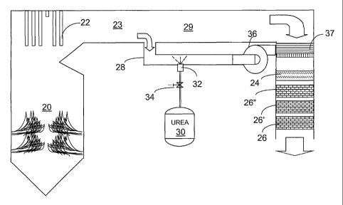
Figure 1 is a schematic representation of one embodiment of the invention
wherein a side stream is separated from the main effluent stream from a
combustor and
urea is injected into it at a temperature sufficient to fully decompose or
otherwise gasify
the urea to active gas species. A large-scale combustor 20 bums fuel with the
resulting
production of nitrogen oxides (NOX) that must be at least partially removed.
The
combustion gases are used to heat water in heat exchanger array 22 before the
combustion gases are exhausted to the atmosphere by passage 23 and apparatus
downstream. A mixing device 24 is optional following adding urea reagent to a
side
stream and combining the side stream with a main combustion gas stream as will
be
explained. The term "side stream" is used herein to refer to a stream of
relatively small
volume relative to the total volume of combustion gases to be treated by
gasified urea and
NOX reduction catalysts, 26, 26' and 26". The side stream can be obtained by
splitting off
a side stream portion 28 of the full stream of combustion gases in passage 23
leaving
principal stream 29 of combustion gases. The separation in various embodiments
will be
made before or after treatment. In addition, the side stream can be formed by
drawing in a
stream of air from sources external of the combustor.
Catalysts 26, 26' and 26" are employed in an array forming a reactor and are
SCR
catalysts as known in the art for reducing NOX utilizing ammonia or urea in
various
hydrolyzed, gasified, pyrolyzed and like forms. Among the suitable SCR
catalysts are
those capable of reducing the effluent nitrogen oxides concentration in the
presence of
ammonia. These include, for instance, activated carbon, charcoal or coke,
zeolites,
vanadium oxide, tungsten oxide, titanium oxide, iron oxide, copper oxide,
manganese
oxide, chromium oxide, noble metals such as platinum group metals like
platinum,
palladium, rhodium, and iridium, or mixtures of these. Other SCR catalyst
materials
conventional in the art and familiar to the skilled artisan can also be
utilized. These SCR
11
CA 02397923 2002-08-09
WO 02/43837 PCT/US01/46415
catalyst materials are typically mounted on a support such as a metal,
ceramic, zeolite, or
homogeneous monolith, although other art-known supports can also be used.
Among the useful SCR catalysts are those representative prior art processes
described below. Selective catalytic reduction processes for reducing NOX are
well
known and utilize a variety of catalytic agents. For instance, in European
Patent
Application WO 210,392, Eichholtz and Weiler discuss the catalytic removal of
nitrogen
oxides using. activated charcoal or activated coke, with the addition of
ammonia, as a
catalyst. Kato, et al., in U.S. Pat. No. 4,138,469 and Henke in U.S. Pat. No.
4,393,031
disclose the catalytic reduction of NOX using platinum group metals and/or
other metals
such as titanium, copper, molybdenum, vanadium, tungsten, or oxides thereof
with the
addition of ainmonia to achieve the desired catalytic reduction. See also EP
487,886,
which specifies a V205/WO3/TiO2 catalyst with a working range of 220 to 280
C. Other
catalysts based on platinum can have operating temperatures even lower, e.g.,'
down to
about 180 C.
Another catalytic reduction process is disclosed by Canadian Patent 1,100,292
to
Knight, which relates to the use of a platinum group metal, gold, and/or
silver catalyst
deposited on a refractory oxide. Mori, et al., in U.S. Pat. No. 4,107,272,
discuss the
catalytic reduction of NO,, using oxysulfur, sulfate, or sulfite compounds of
vanadium,
chromium, manganese, iron, copper, and nickel with the addition of ammonia
gas.
In a multi-phased catalytic system, Ginger, in U.S. Pat. No. 4,268,488,
discloses
exposing a nitrogen oxides containing effluent to a first catalyst comprising
a copper
compound such as copper sulfate and a second catalyst comprising metal
combinations
such as sulfates of vanadium and iron or tungsten and iron on a carrier in the
presence of
ammonia.
The effluent containing the reactant gas is most preferably passed over the
SCR
catalyst while the combustion gases including the gasified urea or other
reagent are at a
12
CA 02397923 2002-08-09
WO 02/43837 PCT/US01/46415
temperature of at least about 100 C and typically between about 180 and about
650 C,
preferably above at least about 250 C. In this manner, the active species
present in the
effluent due to gasification of the reagent solution most effectively
facilitate the catalytic
reduction of nitrogen oxides and condensation of water is controlled. The
effluent will
typically contain an excess of oxygen, e.g., up to about 15% of that required
to fully
oxidize the carbonaceous fuel. Use of the present invention with any of the
above SCR
catalysts (the disclosure of which are specifically incorporated by reference)
reduces or
eliminates the requirement for the transport, storage and handling of large
amounts of
ammonia or amrnonium water.
In Figure 1, the main full stream of combustion gases in duct 23 is split to
provide
side stream 28 and a principal stream 29 of volume greater than the side
stream. Urea,
which decomposes at temperatures above 140 C, is injected from storage 30 via
nozzle
32 with suitable valves 34 and controllers (not shown) into a flue gas stream
28 split off
after a primary superheater or an economizer (shown generally as heat
exchanger 22). To
achieve the goal of gasification for a urea or a urea-related NOx-reducing
reagent,
temperatures above about 300 C are typically employed for gasification.
The urea solution is desirably maintained at a concentration suitable for
storage
and handling without precipitation or other problem. Concentrations of from
about 5 to
70% can be employed with some degree of practicality, but concentrations of
from about
15 to about 50% are more typical. It is an advantage of the invention that the
amount of
water in the urea solution can be varied alone or with steam added to suitably
control the
temperature of the gases in the side stream.
The teinperature of the gases produced by gasifying reagents in this group
should
be maintained at a level that prevents their condensation. Typically, the
temperature
should be maintained at a temperature at least about 150 C, and preferably at
least 200 C.
A preferred temperature range for the gasification and for transfer of the
gases produced
by the noted group of reagents, is from about 300 to about 650 C. Ideally,
the side
13
CA 02397923 2002-08-09
WO 02/43837 PCT/US01/46415
stream 28 would decompose the urea into active species without need for
further heating.
This side stream (e.g., from 0.1 to 25% of the flue gas), typically less than
10% and
usually less than 3%, e.g., from 0.1 to 2%, of the volume of the total
combustion gases
(flue gas), provides the required enthalpy for complete decomposition of urea
and the
sufficient momentum to mix the side stream 28 with the principal stream 29
while the
principal stream 29 can be utilized for further heat exchange.
The vessel carrying the side stream 28 provides the required time and gas
velocity
for urea decomposition. After injection, a residence time from 1 to 10 seconds
is
typically provided to completely decompose urea and promote the reaction
between
IHNCO and water vapor to form ammonia. Side stream gas velocity of 1 to 20
feet per
second is maintained throughout the vessel to optimize vessel dimensions,
achieve plug
flow, enhance the urea droplet dispersion, evaporation, and decomposition into
the side
stream, and minimize droplet impingement on vessel walls. Internal channels
and multi-
walls may be preferred to achieve the optimum gas velocity and to minimize
heat loss to
outside environment. The optimum vessel design can be derived by using, among
others,
well-established design tools such as computational fluid-dynamics model.
The urea injection nozzle 32 introduces well-defined droplets. Both air
assisted
atomizer or a mechanical atomizer can be utilized. Droplet sizes less than 500
microns
but typically less than 100 and preferably below 50 microns are desirable to
rapidly
evaporate and decoinpose urea droplets. Also in consideration of vessel size,
small and
slow droplets generated from, e.g., ultrasonic nozzles can be more desirable
than large
and fast droplets. If desired, steam can be introduced as necessary or
desired. (See
Figures 7-9, in this regard.) This side stream 28 can then be directed to an
injection grid
37 (or other suitable introduction device or apparatus such as a traditional
ammonia
injection grid) ahead of SCR reactor containing catalysts, e.g., 26, 26' and
26". In this
embodiment, a high temperature blower 36 is employed to provide a suitable
injection
pressure, e.g., about 1 psig or less, for the ammonia injection grid 37 and
additionally
14
CA 02397923 2002-08-09
WO 02/43837 PCT/US01/46415
provides mixing. Alternatively, a high temperature blower 36 can be located
upstream of
urea nozzle 32 instead of the depicted location.
A traditional ammonia injection grid 37 with deilsely located nozzles requires
as
low as 0.1% of the total combustor flue gas as the side stream. A static mixer
24 can be
used if desired. Alternatively, injection grid 37 can comprise fewer and
sparsely-placed
nozzles or openings with a static mixer 24 located downstream to obtain a
uniform
distribution. This alternate design may reduce cost and maintenance associated
with the
injection grid. The mixing with the flue gas is facilitated due to an order of
magnitude
higher mass of side stream, e.g., 1 to 2% of the flue gas, compared to that
injected
through an ammonia injection grid (AIG) in a traditional ammonia SCR process.
Thus,
the current embodiment provides the flexibility to the type of injection grid
depending on
the application requirements.
It is an advantage of this and other embodiments of the invention that because
relatively large volumes of side stream gases are mixed with the urea solution
prior to
introducing the gases into the SCR catalyst, an overt mixing procedure is not
essential. It
will be advantageous in many cases, especially where there is a high degree of
fluctuation
in gas volumes, to provide means for mixing the gases at one or more stages.
Among the
suitable mixing means are static mixers, cyclones, blowers and other process
equipment
that by design or effect mixes the gases.
It is another advantage of this embodiment of the invention that by utilizing
the
side stream comprised of combustion gases prior to full heat exchange, the
enthalpy of
the gases is utilized for gasification by direct heat exchange with the
aqueous urea
solution. Surprisingly, calculations will show that direct heat exchange in
this manner
using supplementary heat only as needed under low-load conditions - when the
need for
NOX reduction is also low - will be much more efficient than employing
supplementary
heat in a cold stream to gasify urea. Advantageously, also, the addition of
supplemental
heat to the side stream can be an effective means to control the temperature
in the side
CA 02397923 2002-08-09
WO 02/43837 PCT/US01/46415
stream for consistent urea decomposition and SCR catalyst and maintain both
temperatures within its effective temperature range.
Figure 2 illustrates an embodiment similar to that of Figure 1, but provides
heater
38 to enable increasing the temperature of the side stream 28 sufficiently to
assure
breakdown of the urea as needed. This is especially useful when output is low
for a
boiler. It is an advantage of this arrangement that when heat is required, the
amount
required is far less than would be needed to heat either the entire effluent
or simply the
urea. A high temperature blower 36, located downstream of urea nozzle 32, can
be
located upstream of heater 38 instead of the depicted location. A heater 38
shown as a
burner can be replaced with a steam coil heater, heat exchanger or other means
to transfer
heat to the side stream 28.
Figure 3 is a scheinatic representation of another embodiment of the invention
wherein side stream 28 is separated from the main effluent stream from a
combustor and
heated as needed prior to injecting urea into it. The two streams (23 and 28)
are combined
and passed through a cyclone 40 to effect particle separation and complete
mixing. A
high temperature blower 36, located downstream of urea nozzle 32, can be
located
upstream of heater 38. A heater 38 can be replaced with a steam coil heater,
heat
exchanger or other means to transfer heat to the side stream 28.
Figure 4 is a schematic representation of another embodiment of the invention
wherein side stream 28 is separated from the main effluent stream 23 from
combustor 20
and is passed through a cyclone 40 (or other particle separating device or
apparatus) prior
to heating as needed by heater 38 and injecting urea into it via injector 32.
A high
temperature blower 36,1ocated downstream of urea nozzle 32, can be located
upstream of
heater 38 or a cyclone separator 40. A heater 38 can be replaced with a steam
coil heater,
heat exchanger or other means to transfer heat to the side stream 28.
16
CA 02397923 2002-08-09
WO 02/43837 PCT/US01/46415
Figure 5 is a schematic representation of an embodiment of the invention
similar
to that in Figure 4, wherein side stream 28 is separated from the main
effluent stream 23
from a combustor 22 is heated and urea is injected into it just prior to or in
cyclone 40 (or
other particle separating device or apparatus). The resulting treated stream
is passed via
blower 36 though an injection grid 37 (or other suitable introduction device
or apparatus)
ahead of the SCR reactor. Also, an optional static mixer 39 is illustrated. A
high
temperature blower 36, located downstream of cyclone 40, can be located
upstream of
heater 38. A heater 38 can be replaced with a steam coil heater, heat
exchanger or other
means to transfer heat to the side stream 28.
Figure 6 is a schematic representation of another embodiment of the invention
wherein a stream of air is forced into duct 128 and heated, and urea is
injected into it via
injector 32. The resulting stream is then passed through a mixer and injection
grid as it is
combined with the effluent stream from a combustor and passed through an SCR
reactor.
This embodiment shows heat exchanger 45 and burner 38, but either or both can
be
employed as needed. Other means to transfer heat to. the side stream 28 can
replace the
heat exchanger 45 or a burner 38.
This embodiment is useful in situations where the configuration of combustor
20
does not easily permit construction of a side stream of combustion gases and,
therefore,
requires additional heat. This additional heat can be lessened by using the
preheated
combustion air commonly available in utility boilers.
Figure 7 is a schematic representation of another embodiment of the invention
similar to Figure 6, wherein steam is introduced by means 50 as the heat
source.
Figure 8 is a scheinatic representation of another embodiment of the invention
similar to Figure 7, wherein the steam source 50 is located following
introduction of the
urea.
17
CA 02397923 2002-08-09
WO 02/43837 PCT/US01/46415
Figure 9 is a schematic representation of another embodiment of the invention
similar to Figure 6, wherein a side stream 228 is formed from combustion gases
following treatment in the SCR catalyst reactor. This embodiment has the
advantage that
the gases have considerable heat value, especially if withdrawn prior to using
them to
preheat the combustion air.
Figure 10 is a schematic representation of another embodiment of the invention
similar to Figure 9, wherein a side stream 328 is formed from combustion gases
following treament in the SCR catalyst reactor and downstream particulate
collection
device 60 such as an electrostatic precipitator, bagfilter, or a cyclonic
separator. While
gases have less heat value than the previous representation, this scheme
offers an
advantage of being substantially particulate free when applied on solid or
liquid fired
combustors. Low particulates minimize maintenance requirements.
In Figure 11, a modification of urea injection from Figure 6 is represented.
Instead of aqueous urea injection, a finely ground, pulverized or micronized
solid urea is
injected using pneumatic carrier air via line 31 and nozzle 232 from line 234.
This solid
urea injection can be adapted into all previous representations. Without
water, solid urea
has the advantage of lower heating requirements.
The above description is intended to enable the person skilled in the art to
practice
the invention. It is not intended to detail all of the possible modifications
and variations
that will become apparent to the skilled worker upon reading the description.
It is in-
tended, however, that all such modifications and variations be included within
the scope
of the invention that is seen in the above description and otherwise defined
by the
following claims. The claims are meant to cover the indicated elements and
steps in any
arrangement or sequence which is effective to meet the objectives intended for
the
invention, unless the context specifically indicates the contrary.
18