Note: Descriptions are shown in the official language in which they were submitted.
CA 02398044 2002-08-20
091780-41330
LIQUID VAPORIZATION DEVICE AND BOTTLE
Backaround
The present invention relates to liquid vaporization devices and, more
particularly, to a device that vaporizes a liquid perfume and to a specialized
bottle
that can be used therewith.
There are, of course, a number of commercial devices currently on the
market that are capable of vaporizing an aroma producing liquid in order to
freshen
a room and to rid that room of annoying and undesirable odors. Of the typical
commercial devices, there is the type that includes a housing that receives a
liquid
containing bottle such that the user can employ the device to vaporize the
liquid
within the bottle and, when the supply of liquid within a particular bottle
has been
expended, the user can simply remove the empty bottle and replace it with a
full
bottle to continue the utilization of the device. As such, the typical device
comprises a housing having a heater contained therein and which interacts with
a
wick extending upwardly from the bottle.
The heater, therefore, must be in close proximity to the wick when the
bottle is interfitted to the housing so that the heater for that device can
effectively
and efficiently vaporize the liquid that is present in the wick. In some
vaporizing
devices, the heater is an annular unit that surrounds the wick and therefore
it is
critical, in such devices, that the wick be properly positioned with respect
to the
heater and be capable of easily and automatically be located in such position
when
a bottle is inserted in to the vaporization device. The heater warms the wick,
thereby enhancing the vaporization process, and which also draws that liquid
upwardly from that bottle. The bottle itself therefore requires an opening at
the
top surface such that the wick can extend upwardly through that opening and
into
CA 02398044 2002-08-20
091780-41330
the housing of the particular vaporization device so that the wick is properly
aligned with the heater.
One of the drawbacks to current liquid vaporization devices, howaver, is
that each bottle is unique to a particular housing, that is, once the consumer
has
purchased a liquid vaporization device, there is a limited market to the
purchase of
replacement bottles and only a certain bottle will interact with a housing of
any
individual manufacturer. For example, two of the popular commercial liquid
vaporization devices currently on the market are the Wizard device distributed
by
Reckitt Benckiser, Inc, of Wayne, NJ and the Glade device manufactured by S.C.
Johnson and Son of Wisconsin. Each device has different dimensions of its
housing that accepts a bottle filled with liquid perfume and each bottle is
differently dimensioned such that the bottle presently sold to be used with
the
Glade device cannot be used with the Wizard device and vice versa.
Not only ace there dimensional differences, but with the Wizard device, the
bottle has an annular collar that is snap fitted to a movable member to retain
the
bottle in its operative position to the housing and there is a release
mechanism
that moves that movable member to release the bottle therefrom. As such, with
the bottle adapted to be interfitted to the Wizard device, there needs to be a
annular collar that is dimensioned so as to properly cooperate with the snap
in and
release mechanism. In addition, with the Wizard unit, as with other bottles,
and
as explained, the location of the opening in the bottle through which the wick
extends, is important and in the Wizard device that bottle opening is off
center,
that is, it is not centered between the front and rear surfaces of the bottle
as it is
positioned within the housing of the Wizard device. As used herein, the rear
surface of a bottle is the surface that faces the vaporization device and the
front
surface faces outwardly away from that device.
CA 02398044 2002-08-20
- 3 - 091 ?80-41330
Accordingly, with the Wizard device, taking a dimension of the bottle along
a centerline or plane extending at a right angle to the rear surface of the
housing
such that the centerline passes through the front surface of the bottle and
the rear
surface of the bottle, the opening for the wick, and, of course, the wick
itself, is
S located closer to the rear surface than the front surface.
With the Glade device, the location of the opening in the upper surface of
the bottle is in an entirely different position with respect to its front and
rear
surfaces and, again, such location is essential to the proper interfitting of
the
bottle into the housing of the Glade device. Thus, in the Glade device, the
location of its opening, and, of course, the corresponding wick that extends
upwardly from the opening, is positioned approximately centered between its
front
and rear surfaces. With the bottle used in the Glade device, the bottle also
has
two oppositely disposed projections that interfit into corresponding shaped
openings in the housing so that the projections snap into the openings in the
housing to retain the bottle in its operative position and the bottle can be
snapped
out of that position by the inherent flexibility of the housing. Those
projections
are, therefore, formed in the front and rear surfaces of the bottle for the
Glade
device, and, therefore, generally at equal distances from the centerline of
the
opening in the upper surface of the Glade bottle.
As can be seen, the differences in the current bottles for the Glade and
Wizard devices, be it based upon the dimensions of the external surfaces or in
the
location of the opening for the wick, makes the bottles that interfit into
those
devices unique to each intended device and the interchangeability not
possible,
that is, a bottle intended for a Glade device simply cannot be used with a
Wizard
device and vice versa.
Accordingly, the consumer cannot have the versatility of having a differing
brand of vaporization devices without having to make sure the proper bottle is
CA 02398044 2002-08-20
- 4 - 091780-41330
purchased for that specific vaporization device and it is possible for the
consumer
to actually purchase the incorrect bottle and thus be thwarted in the desire
to
replace an existing, empty bottle. In addition, the consumer is sometimes
inconvenienced in that a local store may stock only one brand of liquid
vaporization device and which is not compatible with the device that is being
used
by the consumer, thereby requiring the consumer to locate another supplier of
the
correct bottle.
In addition, aside from the lack of versatility in purchasing bottles that are
specific to a particular vaporization device, it is more convenient for the
consumer
to have the ability to purchase a range of scents, and a particular desired
scent
may be available only from a competing manufacturer of the consumers devices
and therefore the consumer cannot use that particular scent due to the
incompatibility of the bottle containing that scent with the device in use by
the
consumer.
In any event, it would be advantageous for the consumer to be able to
purchase a single bottle that is compatible physically with more than one
brand of
liquid vaporization device so that such consumer can simply purchase the
bottle
having the desired scent and be able to use that bottle irrespective of the
brand of
the liquid vaporization device used by the consumer.
Summary of the Invention
Accordingly, the present invention relates to a liquid vaporization device and
bottle that interfits therewith and to a specially constructed bottle that can
fit into
any of a plurality of housings of such vaporization devices and, at least into
those
housings of the Glade and the Wizard liquid vaporization devices.
CA 02398044 2002-08-20
- 5 - 091780-41330
Accordingly the bottle of the present invention has solved the lack of
interchangeability of the aforementioned bottles for the commercial Glade and
Wizard liquid vaporization devices by providing a neck having an opening along
with a plurality of front and rear external surfaces that are selectable by
the user,
that is, the bottle is capable of being utilized in a multiplicity of
orientations with
respect to the particular housing of a liquid vaporization device.
The bottle of this invention can be oriented in one position wherein the
opening is centrally located between the front and rear surfaces of the bottle
as it
is interfitted to the Glade liquid vaporization device with the front and rear
surfaces additionally having projections extending out therefrom to snap
within
corresponding alignment holes in the Glade housing for that device. Thus, in
such
orientation, the bottle is well adapted to be interfitted to the Glade device.
By rotating the present bottle a predetermined amount, or number of
degrees, a different front and rear surface is presented and where the
upwardly
facing opening is now closer to the rear surface than the front surface, i.e.
offset
from the center location between the front and rear surfaces, and is therefore
adapted to be interfitted to the housing of the Wizard liquid vaporization
device.
There is additionally formed an annular collar so that the bottle, in this
orientation,
can be interfitted to and held in the housing of a Wizard device.
Thus, by simply rotating the bottle, two different sets of front and rear
surfaces are utilized, each having the proper characteristics, dimensions and
features necessary for the proper fitting of the bottle into either the Glade
of the
Wizard device and with the opening located in the proper positioned to operate
with that particular device. With each orientation, the bottle includes a
locking
feature that cooperates with a corresponding feature on the Glade or Wizard
device housing to retain the bottle in its operative position. In the
preferred
CA 02398044 2002-08-20
6 - 091780-41330
embodiment, that amount of rotation used to orient the bottle with the
differing
front and rear surfaces to carry out the present invention is 90 degrees.
Additional features and advantages of the invention will become apparent
to those skilled in the art upon consideration of the following detailed
description
of preferred embodiments exemplifying the best mode of carrying out the
invention.
Brief Description of the Drawinas
-
FIG. 1 is perspective view of a bottle for use with a liquid vaporization
device constructed in accordance with the present invention and having first,
second, third and fourth external surfaces;
FIG. 2 is a side view of the bottle of Fig. 1 facing the third surface
thereof;
FIG. 3 is a side view of the bottle of Fig. 1 facing the second surface
thereof;
FIG. 4A is a front view of a prior art liquid vaporization housing utilizing a
prior art bottle;
FIG. 4B is a front view of the prior art liquid vaporization housing of Fig.
4A
utilizing a bottle constructed in accordance with the present invention;
FIG. 5A is a side view of a prior art liquid vaporization housing utilizing a
prior art bottle; and
FIG. 5B is a side view of the prior art liquid vaporization housing of Fig. 5A
utilizing a bottle constructed in accordance with the present invention.
CA 02398044 2002-08-20
091780-41330
Detailed Description of the Invention
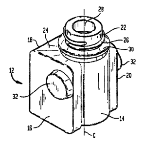
Referring now to Fig. 1, there is shown a perspective view of a bottle 12
constructed in accordance with the present invention. In Fig 1, it can be seen
that
there are basically four external surfaces to the bottle 12. For purposes
explaining
the present invention the external surfaces are defined in Figure 1-3 as a
first
external surface 14, a second external surface 16, a third external surface 18
and
a fourth external surface 20. The first external surface 14 is preferably
arcuate in
configuration, that is, it is curved outwardly, while the surfaces of second,
third
and fourth external surfaces 16, 18, and 20, respectively, are generally
planar,
however, it will become apparent that any of the external surfaces may be
arcuate
or planar and still be within the spirit of the present invention. As an
example, in
the preferred embodiment, the width of the first and third external surfaces
14, 18
is about 32.3 mm. white the width of the second and fourth external surfaces
16
and 20 is about 35.6 mm.
A neck 22 extends upwardly for the upper surface 24 of the bottle 12 and
the neck 22 is preferably provided with external threads 26 so that a
protective
cap (not shown) may readily be secured to the bottle 12 to contain the
contents
of the bottle 12 prior to use. In the preferred embodiment, the overall height
of
the bottle 12 from the bottom of the bottle 12 to the top of the neck 22 is
about
52 mm. There is an opening 28 that passes through the neck 22 to communicate
with the interior of the bottle 12, and, as will be later explained, a wick is
adapted
to extend upwardly through the opening 28 so that a liquid contained within
the
bottle 12 can pass through the wick to be vaporized to the atmosphere.
There is also formed integral with the neck 22 an annular collar 30 that is
dimensioned to be a predetermined diameter and location on the bottle 12 for
purposes that will also be later explained. There are also a pair of outwardly
CA 02398044 2002-08-20
8 - 091780-41330
extending projections 32 that are formed in the second and fourth external
surfaces 16, 20 and are oriented opposite each other and generally in
alignment
with the opening 28 in the neck 22, that is, the longitudinal center line C of
the
opening 28 and the center line joining the projections 32 would be in the same
plane.
Taking Fig 2 in connection with Fig. 1, it can be seen that the center line C
of the opening 28 is also oriented about midway between the second and fourth
external surfaces 16, 20, show by the distances D in figure 2.
-
Turning now to Figure 3 in connection with Figure 1, it can also be seen
that the centerline C of the opening 28 is offset with respect to the midpoint
between the first and third external surfaces 14 and 18. For example in Figure
3,
the mid point between the first and the second external surfaces 14 and 18 is
shown as point M and the centerline of the opening 28 is offset with respect
to
that mid point M by a predetermined dimension d. Fig. 3 also shovrs the
alignment between the centerline of the projections 32 and the centerline C of
the
opening 28. In the preferred embodiment, the approximate distance from the
second external surface 18 to the centerline C is about 23.1 mm and from that
centerline C to the first external surface 14 is about 12.5 mm.
Turning now to Figs. 4A and 4B, there is shown front views of a
commercial liquid vaporization device having a housing 34 that is basically
typical
of the Glade device that is currently on the market. In Figure 4A, there is a
standard prior art bottle 36 currently sold with or sold to be used with the
Giade
device and is affixed in its operative position to the housing 34 and in
Figure 4B,
there is affixed to the housing 34 the bottle 12 constructed in accordance
with
the present invention.
CA 02398044 2002-08-20
- 9 - 091780-41330
Taking Fig: 4A first, it can be seen that the housing 34 includes a annular
heater 38 that surrounds the wick 40 extending upwardly from the bottle 36.
Thus, when the bottle 36 is in its operative position, as shown, the wick 40
passes through the annular heater 38 so that the heater 38 can heat the
volatile
liquid within the wick 40 and vaporize that liquid to be exhausted into the
surrounding environment.
The housing 34 also includes two alignment holes 42 (only one of which is
shown in Figure 4A) that are oppositely oriented such that two projections 44
on
the bottle 36 can be snapped into the alignment holes 42 as the bottle 36 is
inserted into its operative position within the housing 34 to hold the bottle
36 in
that operative position and, by predetermining the dimension A, it is assured
that
the wick 40 is sufficiently long so as to pass sufficiently through the
annular
heater 38 when the lower edge of the projections 44 are snap fitted into the
corresponding alignment holes 42.
Thus, in Figure 4B, the same housing is used as representative of the Glade
liquid vaporization device and therefore the dimension A is still important to
assure
that the wick 46 of the bottle of this invention is sufficiently long to pass
within
the annular heater 38. Also of critical dimension, and referring also back to
Figures 1 and 3, in Figure 3 the bottle 12 is shown in the same orientation as
in
the front view of Figure 4B such that the wick 46 extending from the opening
28
is located at the midpoint between the front external surface 48 and the rear
external surface (not shown in Fig. 4B). To put the orientation in
perspective, and
referring to Figs 1-3 and 4B, the front external surface 48 is the external
surface
that faces away from the housing 34 and is, in effect, the second external
surface
16 of Figs 1-3 and the rear surface of Fig 4B, not shown in Fig 4B, that is,
the
external surface facing the housing 34 is the fourth external surface 20 of
Figs. 1-
3. As can also be seen, the bottle 12 can be rotated 180 degrees and still
interfit
CA 02398044 2002-08-20
- 10 - 091780-41330
within the housing 34, that is, the bottle 12 would be a mirror image of the
bottle
_ 12 shown in the orientation of Fig. 4B.
Therefore, in order to fit within the housing 34 of the Glade liquid
vaporization device, the bottle 12 must be orientated such that the second
external surface 16 or the fourth external surface 20 of Figs. 1-3 is the
front
surface 48 of Figure 4B and the fourth external surface 20 or the second
external
surface 16 of Figure 1-3 is the rear external surface of the bottle of Figure
48,
that is, the bottle 12 can be placed in the Glade device in either of two
positions
that are 180 degrees apart. -
Turning now to Figs 5A and 5B, there is shown side views of a commercial
liquid vaporization device having a housing 52 that is basically typical of
the
Wizard device that is currently on the market. In Figure 5A, there is a
standard
prior art bottle 54 currently sold to be used with the Wizard device and is
affixed
in its operative position to the housing 52 and in Figure 5B, there is affixed
to the
housing 52 the bottle 12 constructed in accordance with the present invention.
Taking Figure 5A first, it can be seen that the housing 52 includes an
annular heater 56 that surrounds the wick 58 extending upwardly from the
bottle
54. Thus, when the bottle 54 is in its operative position, as shown, the wick
58
passes through the annular heater 56 so that the heater can heat the volatila
liquid
within the wick 58 and vaporize that liquid to be exhausted into the
surrounding
environment.
The housing 52 also includes downwardly extending latches 60 that grasps
the bottle 54 underneath the annular collar 64 formed in the neck 66 of the
bottle
54. The interaction between the downwardly extending latches 60 thus holds the
bottle 54 in its operative position as show in Figure 5A. Again, by
predetermining
the dimension A, it is assured that the wick 58 is sufficiently long so as to
assure
CA 02398044 2002-08-20
11 - 091780-41330
that the wick 58 passes through the annular heater 56 when the downwardly
_ extending latches 60 have securely grasped and are holding the bottle 54 in
the
operative position as shown in Figure 5A.
Thus, in Figure 5B, the same housing is used as representative of the
Wizard liquid vaporization device and therefore the dimension A is still
important
to assure that the wick 46 of the bottle of this invention is sufficiently
long to
pass within the annular heater 56. Also of critical dimension, and referring
also
back to Figures 1 and 2, in Figure 3 the bottle 12 is shown in the same
orientation
as in the side view of Figure 5B such that the wick_48 extending from the
opening
28 is located offset rearwardly in the housing 34 from the point M that is the
midpoint between the front external surface 48 and the rear external surface
50.
To put the orientation in perspective, and referring to Figs 1-3 and 5B, the
front
external surface 48 is the external surface that faces away from the housing
34
and is, in effect the third external surface 18 of Figs 1-3 and the rear
external
surface 50 of Fig 4B, i.e. the external surface facing the housing 34, is the
first
external surface 14 of Figs. 1-3.
Therefore, in order to fit within the housing 34 of the Wizard liquid
vaporization device, the bottle 12 must be orientated such that the third
external
surface 18 of Figs 1-3 is the front surface 48 of Figure 5B and the first
external
surface 14 of Figure 1-3 is the rear external surface 50 of the bottle 12 of
Figure
5B.
Therefore, it can be seen that the present bottle 12 can be interfitted into
the Glade vaporization device or the Wizard vaporization device by simply
rotating
the bottle 12 so that the proper external surfaces are in the correct
orientation
with respect to the particular commercial device, be it the Glade device or
the
Wizard device.
._ CA 02398044 2002-08-20
12 - 091780-41330
To summarize, with the present bottle 12, it is possible to interfit that
bottle 12 into either the housing 34 of the Glade device as shown in Figure 4A
and 4B or the Wizard device as shown in Figure 5A and 5B by simply rotating
the
bottle about its centerline C passing through the opening 28 and the neck 22
so
S that different external surfaces are facing toward and away from the housing
34
and 52. For example, when the bottle 12 is intended to be interfit into the
housing 34 of the Glade device, the bottle is oriented such that the second
and
fourth external surfaces 16 and 20 as shown in Figs 1-3 are, respectively, the
front and rear surfaces of the bottle 12 when operatively interfitted with
that
Glade device and shown in Figure 4B. On the ocher hand, to interfit the same
bottle 12 into the Wizard device, the bottle 12 is simply rotated 90 degrees
and
inserted into the Wizard device such that the first external surface 14 and
the
third external surface 18 of Figs. 1-3 are, respectively, the rear surface 50
and the
front surface 48 of the bottle 12 when in the operative position in that Glade
device, shown in Figure 5B.
Accordingly, the present bottle 12 has been specifically dimensioned to be
able to be interfitted with either the Glade device or the Wizard device
through the
rotation of the bottle 12 such that the proper dimensions are in the correct
location to insert that bottle 12 into either device and thus the same bottle
can be
sold commercially at a greater convenience to the user. It should be noted,
that
the present bottle can only be interfitted to the Wizard unit in one
orientation and
can thereafter be interfitted to the Glade device by a 90 degree rotation of
the
bottle 12 in either direction, that is, the bottle 12 can fit into the Glade
device in
two orientations, about 180 degrees apart, with either the second external
surface
16 or the fourth external surface 20 facing outwardly.
Those skilled in the art will readily recognize numerous adaptations and
modifications which can be made to the liquid vaporization device and bottle
which will result in an improved device and method of using the same yet all
of
,_ CA 02398044 2002-08-20
- 13 - 091780-41330
which wilt fall within the scope and spirit of the present invention as
defined in the
following claims. Accordingly, the invention is to be limited only by the
following
claims and their equivalents.