Note: Descriptions are shown in the official language in which they were submitted.
CA 02398305 2002-07-23
WO 01/54872 PCT/JPO1/00163
1
DESCRIPTION
METHOD FOR FORMING CUT LINES IN SHEET
BACKGROUND OF THE INVENTION
FIELD OF THE INVENTION
The present invention relates to a cut line forming
method for forming a plurality of cut lines of a predetermined
length in a sheet made of paper, a nonwoven fabric, a film,
a composite of a nonwoven fabric and a film, a composite of
a nonwoven fabric and a fibrous web, a composite of a film and
a fibrous web, a composite of a film, a nonwoven fabric and
a fibrous web, or the like.
DESCRIPTION OF THE PRIOR ART
In the general method for forming the cut lines of a
predetermined length in those various sheets, both a cutter
roll having a plurality of cutting blades protruded
intermittently on the outer circumference for setting the
length of the cut lines and an anvil roll having a receiving
face for the cutting blades on the outer circumference are used
and fed at the clearance inbetween with the sheet and are then
turned. During these turns, the sheet is bitten and cut between
the cutting blades and the receiving face so that the cut lines
having the same length as that of the cutting blades are formed
in a plurality of portions of the sheet. The term "cut line"
as used herein is meant to indicate a slit, i. e. , a long narrow
cut which pass through the sheet.
CA 02398305 2002-07-23
WO 01/54872 PCT/JPO1/00163
2
In the cut line forming method of the prior art, however,
the length of the edges of the cutting blades of the cutter
roll ( i. e. , the linear length of the edges extending in a roll
axis direction) is equalized to the length of the cut lines
to be formed in the sheet, and the cutting blades are arrayed
at an interval on the outer circumference of the cutter roll.
With the edges thus being short, the individual cutting blades
are weakened so that they are liable to be worn at their edges
and to be folded or broken.
When intermittent cut lines, as arrayed obliquely with
respect to the MD, are to be formed in a bulky sheet which is
prepared by laying a layer of long fibers opened from TOW or
a layer of split yarns over a base material sheet of a nonwoven
fabric, for example, to have a basis weight of 50 g/m2 or more,
on the other hand, an offset force in a widthwise direction
(CD) is applied to the layer of long fibers or split yarns by
the cutting blades extending obliquely with respect to the
circumferential direction of the cutter roll. As a result,
there will arise a problem that the fiber layer is offset over
the sheet.
As the cutter roll and the anvil roll are turned to form
the cut lines, on the other hand, one cutting blade is pressed
many times by the receiving face. As a result, the edges of
the cutting blades are seriously worn. Moreover, the
receiving face of the anvil roll is hit many times at the same
CA 02398305 2005-02-15
3
portions by the cutting blades so that the receiving face is
also seriously damaged or worn.
SUMMARY OF THE INVENTION
A feature of one embodiment: of the invention is to
provide a method for forming cut: lines in a sheet, which is
enabled to prevent the cutting blades from being worn,
folded or broken, by making the length of the edges of the
cutting blades (i.e., the linear length of the edges
extending in the roll axis direcaion and/or in the roll
circumference direction) larger than that of the cut lines.
Another feature of an embodiment of the invention is to
provide a cut line forming method which makes it hard for an
offset force to act on the fibrous layer on the sheet by
arranging the cut lines in a V-:shaped array.
Still another feature of a preferred embodiment of the
invention is to provide a cut line forming method which is
enabled to elongate the life time of the edges of the
cutting blades by shifting the x~ortions of the edges to abut
against the receiving faces.
According to a first aspect of the invention, there is
provided a cut line forming metr.od comprising: using a
cutter roll having cutting blades protruded on its outer
circumference and an anvil roll for receiving the cutting
blades; feeding a sheet into the clearance between the
cutter roll and the anvil roll; and turning the rolls
individually to form cut lines in
CA 02398305 2002-07-23
WO 01/54872 PCT/JPO1/00163
4
the sheet,
wherein the cutting blades of the cutter roll are formed
into a shape of letter "V", and the anvil roll has receiving
faces of a predetermined width formed at an interval in a roll
axis direction, and
wherein the cutter roll is turned to direct the crests
of the V-shape of the cutting blades forward of the turning
direction thereby to advance cuts from the side of the crests
of the V-shape so that cut lines corresponding to the width
size of the receiving faces may be intermittently formed in
the sheet along the V-shape.
In the invention, the length of the edges of the cutting
blades of the cutter roll (i.e., the length of the edges
extending in the roll axis direction and/or in the roll
circumference direction) is not reduced, but the receiving
faces for receiving the cutting blades are made to have a
predetermined width size, so that the cut lines of the length
corresponding to the width size of the receiving faces can be
formed when the sheet is pressed and cut by the cutting blades
and the receiving faces . This makes it unnecessary to shorten
the edges of the cutting blades so that the cutting blades can
be less worn and can be prevented from being folded or broken.
In the invention, when the obliquely arrayed cut lines
are to be formed in a bulky sheet which is prepared by laying
a layer of long fibers opened from the TOW or a layer of split
CA 02398305 2002-07-23
WO 01/54872 PCT/JPO1/00163
yarns over a base material of a nonwoven fabric or a film to
have a basis weight of 50 g/m2 or more and which is liable to
be dispersed in the basis weight in the widthwise direction,
for example, the cut lines are arrayed in the v-shaped pattern,
and the abutting portions between the cutting blades and the
receiving faces are advanced from the crests to the skirts of
the V-shape. As the two rolls turn, therefore, substantially
homogeneous forces act to the right and left in the widthwise
direction ( CD ) upon the sheet at the layer of the long f fibers
or the layer of the split yarns across the crests of the v-shape.
As a result, no extremely widthwise offset force will act on
the layer of the long fibers cr the like of the sheet so that
the layer of the long fibers or the like is hardly offset or
dispersed in the bulk.
Here, the V-shaped pattern of the cutting blades in the
invention may be to have an acute angle or a rounded shape at
the crest. As shown in Fig. 2A, moreover, the trailing end
portion of the skirts of the v-shape of one cutting blade and
the crest of the v-shape of another cutting blade preferably
lie on a common line in the roll axis direction. With the crest
of the v-shape being given the acute angle and laid on the common
line, the pressure on the cutting blades can be easily made
constant when the cutting blades abut against the receiving
faces.
According to a second aspect of the invention, there is
CA 02398305 2002-07-23
WO 01/54872 PCT/JPO1/00163
6
provided a cut line forming method comprising: using a cutter
roll having cutting blades protruded on its outer circumference
and an anvil roll for receiving the cutting blades; feeding
a sheet into the clearance between the cutter roll and the anvil
roll; and turning the rolls individually to form cut lines in
the sheet,
wherein the anvil roll has receiving faces of a
predetermined width formed at an interval in a roll axis
direction,
wherein the receiving faces are formed to shift in the
roll axis direction in accordance with the advance in the
circumferential direction, so that the abutting portions of
the cutting blades against the receiving faces may shift along
the edges of the cutting blades at the next time when the cutting
blades and the receiving faces abut against each other, and
wherein as the cutter roll and the anvil roll turn, the
cut lines corresponding to the width size of the receiving faces
are formed in the sheet and are arrayed at an interval in the
extending direction of the receiving faces.
In this case, the receiving faces may be formed in a
helical shape on the circumference of the anvil roll.
According to a third aspect of the invention, there is
provided a cut line forming method comprising: using a cutter
roll having cutting blades protruded on its outer circumference
and an anvil roll for receiving the cutting blades; feeding
CA 02398305 2002-07-23
WO 01/54872 PCT/JPO1/00163
7
a sheet into the clearance between the cutter roll and the anvil
roll; and turning the rolls individually to form cut lines in
the sheet,
wherein the anvil roll has receiving faces of a
predetermined width formed at an interval in a roll axis
direction,
wherein the cutting blades are formed to shift in the
roll axis direction in accordance with the advance in the
circumferential direction, so that the abutting portions of
the cutting blades against the receiving faces may shift along
the edges of the cutting blades at the next time when the cutting
blades and the receiving faces abut against each other, and
wherein as the cutter roll and the anvil roll turn, the
cut lines corresponding to the width size of the receiving faces
are formed in the sheet and are arrayed at an interval in the
extending direction of the cutting blades.
In this case, the cutting blades may be formed in a helical
shape on the circumference of the cutter roll.
According to the second or third aspect of the invention,
the receiving faces of the predetermined width shift in the
roll axis direction as they extend in the circumferential
direction of the anvil roll, or the cutting blades shift in
the roll axis direction as they extend ~in the circumferential
direction of the cutter roll. As a result, when the edges of
the cutting blades extend continuously, for example, the
CA 02398305 2002-07-23
WO 01/54872 PCT/JPO1/00163
8
abutting portions of the cutting blades against the receiving
faces shift in the edge extending direction as the abutments
are repeated. Therefore, the cutting blades can be prevented
from abutting against the receiving faces exclusively at their
identical portions, thereby to elongate the edge lifetime.
In the invention, the diametrical size of the cutter roll
to the edges of the cutting blades is preferably made different
from that of the receiving faces of the anvil roll.
With the cutter roll and the anvil roll being thus
diametrically different, the cutting blades and the receiving
faces can be prevented from abutting at their identical
positions so that they can be less worn to elongate their
lifetimes.
Moreover, the hardness of the receiving faces of the
anvil roll is preferably lower than that of the cutting blades
of the cutter roll.
In this case, while the cutting work is continued for
a long time, the receiving faces are more easily worn or damaged
than the cutting blades. However, the wear or damage of the
receiving faces, as formed on the outer circumference of the
anvil roll, can be easily remedied by the simple method of
polishing the receiving faces while turning the anvil roll.
The sheet to be cut in the invention is, for example,
made of paper, a nonwoven fabric, a film, a composite of a
nonwoven fabric and a film, a composite of a nonwoven fabric
CA 02398305 2002-07-23
WO 01/54872 PCT/JPO1/00163
9
and a fibrous web, a composite of a film and a fibrous web,
or a composite of a film, a nonwoven fabric and a fibrous web.
However, the invention should not be limited to the cutting
of these sheets.
The invention is especially effective where the cut lines
are to be formed in the sheet of which the fibrous web is a
layer of long fibers such as fibers opened from TOW or split
yarns so that it is bulky and is liable to be dispersed in the
basis weight.
BRIEF DESCRIPTION OF THE DRAWINGS
Fig. 1 is a perspective view showing a method for forming
cut lines in a sheet according to a first embodiment of the
invention;
Fig. 2A is a development of a cutter roll shown in Fig.
1, and Fig. 2B is a development of an anvil roll shown in Fig.
1;
Fig. 3 is a top plan view showing a cleaning sheet in
which the cut lines are formed by the method shown in Fig. 1;
Fig. 4 is a section taken along line IV - IV of Fig. 3;
Fig. 5A is a development of a cutter roll in a second
embodiment of the invention, and Fig. 5B is a development of
an anvil roll in the second embodiment;
Fig. 6 is a top plan view showing a cleaning sheet in
which the cut lines are formed by the cutter roll and the anvil
CA 02398305 2002-07-23
WO 01/54872 PCT/JPO1/00163
roll shown in Figs. 5A and 5B;
Fig. 7A is a development of a cutter roll in a third
embodiment of the invention, and Fig. 7B is a development of
an anvil roll in the third embodiment;
Fig. 8 is a top plan view showing a cleaning sheet in
which the cut lines are formed by the cutter roll and the anvil
roll shown in Figs. 7A and 7B;
Fig. 9A is a development of a cutter roll in a fourth
embodiment of the invention, and Fig. 9B is a development of
an anvil roll in the fourth embodiment; and
Fig. 10 is a top plan view showing a sheet in which the
cut lines are formed by the cutter roll and the anvil roll s:~own
in Figs. 9A and 9B.
PREFERRED EMBODIMENTS OT THE INVENTION
In Figs. 1 to 4 showing a method for forming cut lines
in a sheet according to a first embodiment of the invention:
Fig. 1 is a perspective view showing the state in which a sheet
is bitten between a cutter roll and an anvil roll; Fig. 2A is
a development of the outer circumference of the cutter roll
shown in Fig. 1; Fig. 2B is a development of the outer
circumference of the anvil roll shown in Fig. l; Fig. 3 is a
top plan view of a cleaning sheet in which the cut lines are
formed by that method; and Fig. 4 is a section taken along line
IV - IV of Fig. 3.
CA 02398305 2002-07-23
WO 01/54872 PCT/JPO1/00163
11
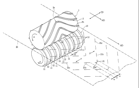
Fig. 1 shows a cutter roll 1 and an anvil roll 10. The
cutter roll 1 and the anvil roll 10 are made of cemented carbide
or tool steel, for example. In this embodiment, a metallic
material making the receiving faces 11 of the anvil roll 10
is less hard than that making the cutting blades 2 of the cutter
roll 1.
As shown in Fig. 1, the cutter roll 1 is turned in the
direction a whereas the anvil roll 10 is turned in the direction
(3. In this case, the turning force is preferably applied to
at least the cutter roll 1. The anvil roll 10 may be given
a turning force synchronized with the cutter roll 1 or may be
set in a freely rotational state to zollow the cutter roll 1.
A sheet 20 is bitten between the cutter roll 1 and the
anvil roll 10 so that it is fed out in accordance with the turning
directions of the individual rolls. In Fig. 1, letters MD
designate the delivery direction of the sheet 20, and letters
CD designate the width direction of the sheet 20 and the axial
direction of the two rolls 1 and 10.
The cutter roll 1 is provided on its outer circumference
with a plurality of cutting blades 2 . These individual cutting
blades 2 are protruded integrally from the outer circumference
of the cutter roll 1. With the outer circumference of the
cutter roll 1 being developed, as shown in Fig. 2A, the
individual cutting blades 2 generally in the shape of letter
"V" are arrayed at a constant interval in the turning direction
CA 02398305 2002-07-23
WO 01/54872 PCT/JPO1/00163
12
and are formed continuously without any interruption in the
roll axis direction (CD). It should be noted that the shape
of the cutting blade as referred herein is meant to indicate
a way in which the edge of the cutting blade is extended, when
the outer circumference of the cutter roll is developed. Each
cutting blade 2 is directed at its crest 2a of the V-shape
forward (i.e., in the direction a) of the turning direction
and at its open sides (or skirts) 2b of the V-shape backward
of the direction a. In this embodiment, the crest 2a of the
V-shape is rounded. However, the crest 2a is preferred to have
an acute angle for keeping a contact pressure between the
cutting blades 2 and the receiving faces 11 of the anvil roll
at a constant level . As shown in Fig . 2A, in addition, it
is preferable that the end portions of the open sides 2b of
any cutting blade 2 and the crest 2a of another cutting blade
2 line on a common line L extending in the roll axis direction.
With this construction, it is possible to keep the contact
pressure between the cutting blades 2 and the receiving faces
11 always at a constant level.
The anvil roll 10 is arranged in parallel with the cutter
roll 1, and these anvil roll 10 and cutter roll 1 are elastically
pushed by the not-shown elastic push means. The anvil roll
10 is provided on its outer circumference with the receiving
faces 11 having a predetermined width size W. The receiving
faces 11 are linearly extended in the turning direction of the
CA 02398305 2002-07-23
WO 01/54872 PCT/JPO1/00163
13
anvil roll 10, as shown in the development of Fig. 2B, so that
they are formed into the cylindrical faces which are extended
to make one round in the turning direction of the anvil roll
10, as shown in Fig. 1. The individual receiving faces 11 are
separated by grooves 12 so that they are spaced at a constant
spacing d in the roll axis direction (CD) of the anvil roll
10.
The width size W of the receiving faces 11 in the roll
axis direction is preferably 1 mm or more, and the spacing d
of the receiving faces 11 in the roll axis direction is
preferably 0.5 mm or more.
In the embodiment shown, the cutting blades 2, as formed
on the cutter roll 1, are formed into the V-shape and
continuously without any interruption in the roll axis
direction of the cutter roll 1. However, it should be noted
that the individual cutting blades 2 of the V-shape according
to the invention may be interrupted at one or two or more
portions midway of the roll axis direction. Accordingly, the
term "V-shape " as used herein should not be construed to
preclude such an uncontinuous V-shape which is interrupted
midway. In this case, however, the extensions of the cutting
blades 2 in the roll axis direction (CD) are required to be
longer than the width size W of one receiving face 11 in the
roll axis direction and to have a length sufficient for abutting
against at least two adjoining receiving faces 11 when the two
CA 02398305 2002-07-23
WO 01/54872 PCT/JPO1/00163
14
rolls 1 and 10 are turned.
As the sheet 20 is fed to the clearance between the cutter
roll 1 and the anvil roll 10, it is delivered out in the MD
by the turning forces of the cutter roll 1 in the direction
a and the anvil roll 10 in the direction (3.
In the construction shown in Fig. 1, the cutting blades
2 are continuous without any interruption in the roll axis
direction of the cutter roll 1. In the anvil roll 10, on the
other hand, the receiving faces 11 having the predetermined
width W are formed at the spacing d in the roll axis direction.
Therefore, the sheet 20 is cut only at portions where the
cutting blades 2 and the receiving faces 11 abut. As a result,
a plurality of cut lines 21 are cut in the sheet 20. The cut
lines 21 are intermittently formed corresponding to the V-
shape of the individual cutting blades 2. Hereinafter, the
term "V-shaped cut lines" is meant to indicate a set of cut
lines, which are intermittently formed corresponding to the
V-shape of one cutting blade 2. The V-shaped cut lines 21 are
arranged at the spacing d in the roll axis direction with such
a width extending in the roll axis direction (CD) as is
equalized to the width size W of the receiving faces 11.
The V-shaped cut lines 21 never fail to include one cut
line forming the crest 21a of the V-shape. In other words,
one of the receiving faces 11 of the anvil roll 10 is positioned
to abut against the crests 2a of the V-shaped cutting blades
CA 02398305 2002-07-23
WO 01/54872 PCT/JPO1/00163
2. The remaining cut lines of the V-shaped cut lines 21 are
intermittently arranged to form the slope portions 21b expanded
backward of the MD from the crests 21a to the open end portions
21c of the V-shape.
In the embodiment shown in Fig. 1, the crests 2a of the
V-shaped cutting blades 2 of the cutter roll 1 a~~e directed
forward (i.e., in the direction a) of the turning direction.
In the sheet 20, therefore, the cut lines 21 are so extended
that their cuts advance from the crests 21a to the open end
portions 21c of the V-shape. When the slope portions 21b of
the cut lines 21 are to be formed, forces F outward of the width
direction ( CD ) are caused to act on the sheet 20 by i.he slope
portionsof the cutting blades2 extending obliquely. However,
these forces F act substantially homogeneously to the right
and left or outward of the widthwise direction across the crests
21a of the V-shape so that neither any offset force nor any
widthwise centralized force acts on the sheet 20. What acts
on the sheet 20 is the widthwise tensions which are caused by
the forces F and F directed homogeneously to the right and left.
Therefore, the sheet 20 is cut without any deformation by the
cutting blades 2 and the receiving faces 11 so that the cut
lines 21 are regularly formed without any distortion or any
displacement.
Especially where the sheet 20 has the following
construction, the homogeneous forces F and F are applied to
CA 02398305 2002-07-23
WO 01!54872 PCT/JPO1/00163
16
eliminate the offset or concentration of a fibrous web 24 on
the sheet 20. In this construction, for example, the sheet
20 is manufactured by laying the fibrous web 24, as made of
long fibers such as fibers opened from TOW or split yarns, over
a base material of nonwoven fabric 23, film or a composite of
the nonwoven fabric and the film, as shown in Fig. 4, so that
it is bulky to have a basis weight of 50 g/m2 or more but is
liable to vary in the basis weight.
In this embodiment, moreover, the diameter of a virtual
cylinder containing the edges of the cutting blades 2 of the
cutter roll 1 is different from that of the receiving faces
11 of the anvil roll 10. Therefore, the cutting blades 2 abut
less repeatedly against the same portions of the confronting
receiving faces 11 so that they abut against different portions
of the receiving faces 11 when the cutter roll 1 is turned.
As a result, the receiving faces 11 are hardly worn or damaged
at their local portions.
On the other hand, the receiving faces 11 of the anvil
roll 10 are made of a less hard material than that of the cutting
blades 2 of the cutter roll 1 so that the receiving faces 11
are worn before the cutting blades 2 after the cutting actions
are repeated for a long time. This makes it possible to delay
the progress of the wear of the cutting blades 2. The wear
or damage on the surfaces of the receiving faces 11 can be
remedied at a simple step by turning the anvil roll 10 to grind
CA 02398305 2002-07-23
WO 01/54872 PCT/JPO1/00163
17
the surfaces of the receiving faces 11.
Fig. 3 is a top plan view showing a cleaning sheet 20A
as an example of the sheet 20, in which the cut lines 21 are
formed by the method shown in Fig. 1, and Fig. 4 is a section
taken along line IV - IV of Fig. 3.
This cleaning sheet 20A is manufactured by laying the
fibrous web 24 over the base material or the nonwoven fabric
23. The nonwoven fabric 23 is exemplified by spun-bonded,
thermal bonded, or spun-lace nonwoven fabric containing
fusible fibers such as those of PET, PE or PP or their composite
fibers. Alternatively, the base material may be exemplified
either by a fusible film in place of the nonwoven fabric 23
or by a laminate of the nonwoven fabric 23 and the film.
The f fibrous web 2 4 is a f fibrous layer made of long f fibers
such as fibers opened from the TOW or split yarns. These fibers
are extended mainly in the delivery direction (MD) of the sheet
20A. The long fibers such as fibers opened from the TOW or
split yarns may be extended as long as the entire length of
the cleaning sheet 20A in the MD, or the fibrous web 24 may
be formed of bundles of fibers shorter than the entire length
in the MD. The fibers making the fibrous web 24 also contain
the fusible fibers such as those of PET, PE or PP or their
composite fibers.
On the two side portions of the cleaning sheet 20A lying
opposite one another in the widthwise direction (CD), there
CA 02398305 2002-07-23
WO 01/54872 PCT/JPO1/00163
18
are disposed holding sheets 25 and 25. These holding sheets
25 and 25 are made of a sheet similar to the nonwoven fabric
23. The nonwoven fabric 23 and the holding sheets 25 and 25
sandwich the two side portions of the fibrous web 24 and are
adhered with a hot-melt adhesive or fused to each other.
In this cleaning sheet 20A, there are formed fused lines
22. The individual fused lines 22 are continuously extended
in a shape of letter "V", which is identical to the V-shape
along which the cut lines 21 are arranged. By these fused lines
22, the nonwoven fabric 23 and the fibrous web 24 are pressed
and fused to each other. These fused lines 22 are formed by
feeding the sheet to the clearance between a heating roll having
a V-shaped pressure portion on the surface and a receiving roll
confronting the heating roll.
When the cleaning sheet 20A thus having the fused lines
22 is fed into the clearance between the cutter roll 1 and the
anvil roll 10, as shown in Fig. 1, the V-shaped cut lines 21
are formed between the fused lines 22 and 22. The nonwoven
fabric 23 and the fibrous web 24 are cut together along those
cut lines 21.
If necessary, moreover, the fibers composing the fibrous
web 24 are napped. In hatched regions 26 in Fig. 3, therefore,
the fibers forming the fibrous web 24 are held by the fused
lines 22 but released at the portion of the cut line 21. As
a result, the cut fibers extending from the fused lines 22 to
CA 02398305 2002-07-23
WO 01/54872 PCT/JPO1/00163
19
the cut line 21 form a brush-shaped portion. Such brush-shaped
portions of the fibrous layer are formed in all the regions
that are defined by the fused lines 22 and the cut lines 21.
In this cleaning sheet 20A, the brush-shaped portions
can wipe off dust or the like. In the remaining regions lacking
the cut lines 21, the fibrous layer extends in a bridge shape
between the fused lines 22 and 22 adjoining in the MD so that
it can trap the dust or relatively large pieces of trash between
the fibers.
Of Figs. 5A and 5B and Fig. 6 showing a second embodiment
of a method according to the invention for forming cut lines
Fig. 5A is a development of the outer circumference of the
cutter roll 1; Fig. 5B is a development of the outer
circumference of an anvil roll 10A; and Fig. 6 is a top plan
view showing a sheet 20B having cut lines.
The cutter roll 1 shown in Fig. 5A is identical to the
cutter roll 1 shown in Fig. 2A to have the generally V-shaped
cutting blades 2 formed at the constant interval in the turning
direction (or in the direction a). The individual cutting
blades 2 are formed continuously without any interruption in
the roll axis direction (CD).
On the outer circumference of the anvil roll l0A shown
in Fig. 5B, there are formed the receiving faces 11 of the
predetermined width W and the grooves 12 for separating the
receiving faces 11 at the spacing d in the roll axis direction.
CA 02398305 2002-07-23
WO 01/54872 PCT/JPO1/00163
The width size W of the receiving faces 11 in the roll axis
direction (CD) is preferably 1 mm or more, and the spacing d
of the receiving faces 11 in the roll axis direction (CD) is
preferably 0.5 mm or more.
However, the receiving faces 11 are so formed at an angle
of inclination E3 with respect to the circumrerential direction
that they may shift in the roll axis direction (CD) as they
go in the circumferential direction (or in the turning
direction, i.e., the direction (3) . In the anvil roll 10A, more
specifically, the receiving faces 11 of the predetermined width
W are formed helical in the roll axis direction.
The inclination angle 8 is not especially limited if it
exceeds 0 degrees. If this angle 8 is so set that the receiving
faces 11 are displaced by W+d in the roll axis direction when
the anvil roll l0A makes one turn, however, they form one
helical line continuing in the circumferential direction of
the anvil roll 10A. Here, the receiving faces 11 may form two
or more helical lines continuing in the circumferential
direction of the anvil roll.
If the cutting blades 2 of the cutter roll 1 are inclined
at an angle 81 with respect to the roll circumference direction,
on the other hand, the angle 8 is preferably ( 1 /2 ) ~81 or less .
Fig. 6 shows the sheet which is fed to the clearance
between the cutter roll 1 and the anvil roll 10A, as shown in
Figs. 5A and 5B, to form the cut lines 21. This sheet shown
CA 02398305 2002-07-23
WO 01/54872
PCT/JPO1/00163
21
in Fig. 6 is the cleaning sheet 20B, which has the same structure
as that of the cleaning sheet 20A shown in Figs . 3 and 4 . In
the cleaning sheet 20B shown in Fig. 6, the fused lines 22 are
formed as in the cleaning sheet 20A shown in Fig. 3, and the
cut lines 21 are formed between the fused lines 22.
In the embodiment shown in Figs. 5A and 5B and Fig. 6,
the receiving faces 11 of the anvil roll l0A are formed
helically in the roll axis direction, so that the cut lines
21 formed in the cleaning sheet 20B are formed to have a length
corresponding to the width size W in the roll axis direction
( CD ) of the receiving faces 11 and are arrayed to have the angle
8 with respect to the MD in accordance with the extending
direction of the receiving faces 11.
In the embodiment shown in Figs. 5A and 5B and Fig. 6,
the receiving faces 11 of the anvil roll l0A are helically
formed. Therefore, the portions of the edges of the cutting
blades 2 to abut against the receiving faces 11 shift along
the edges of the cutting blades 2 in accordance with the turns .
For example, when the predetermined cutting blade 2, as
indicated at (i) in Fig. 5A, abuts against the receiving face
11 of the anvil roll 10A, the cut line 21 is formed, as indicated
at ( ii ) in Fig . 6 . After this , when the cutter roll 1 and the
anvil roll l0A turn so that the cutting blade 2 at (i) abuts
against the receiving face 11 once again, the abutting portion
of the cutting blade 2 at (i) against the receiving face 11
CA 02398305 2002-07-23
WO 01/54872 PCT/JPO1/00163
22
shifts in the roll axis direction ( CD ) along the edge of the
cutting blade 2.
For this action, it is necessary that the diameter of
the virtual cylinder containing the edges of the cutter roll
1 be different from the diameter of the receiving faces 11 of
the anvil roll 10A. With this diametrical difference, the
portion of the receiving face 11 to receive the cutting blade
2 at (i) shifts in the circumferential direction as the turns
of the rolls advance. The receiving faces 11 are inclined to
shift in the roll axis direction as they move in the
circumferential direction of the anvil roll 10A. Therefore,
the abutting portion of the cutting blade 2 at ( i ) against the
receiving face 11 shifts in the roll axis direction along the
edge of the cutting blade 2 in accordance with the inclination
(8) of the receiving faces 11.
With the receiving faces 11 being inclined with respect
to the circumferential direction and with the two rolls being
given the different diameters, the abutting portions of the
cutting blades 2 against the receiving faces 11 shift along
the edges of the cutting blades 2 as the rolls turn, and the
cutting blades 2 do not abut the same portions of the receiving
faces 11. Therefore, both the cutting blades 2 and the
receiving faces 11 are neither worn nor damaged locally at the
same portions.
Figs. 7A and 7B and Fig. 8 show a third embodiment of
CA 02398305 2002-07-23
WO 01/54872 PCT/JPO1/00163
23
the invention. The anvil roll l0A shown in Fig. 7B is identical
to that shown in Fig. 5B. In a cutter roll lA shown in Fig.
7A, however, cutting blades 2A, as protruded from the outer
circumference, are extended at a right angle with respect to
the turning direction (or the direction a) and linearly in the
roll axis direction (CD).
In a cleaning sheet 20C, as shown in Fig. 8, cut lines
21A are formed by the cutter roll lA and the anvil roll 10A,
as shown in Figs. 7A and 7B. The cleaning sheet 20C shown in
Fig. 8 is given a layer structure identical to those shown in
Figs. 3, 4 and 6 by laminating the nonwoven fabric 23 and the
fibrous web 24. In the cleaning sheet 20C shown in Fig. 8,
a set of cut lines 21A are formed by one cutting blade 2A to
extend linearly in the widthwise direction (CD) like a
perforated line. Between these sets of the cut lines 21A, there
are interposed fused lines 22A extending linearly in the CD
to bond the nonwoven fabric and the fibrous web.
The diameter of the virtual cylinder containing the edges
of the cutting blades 2A of the cutter roll lA, as shown in
Fig. 7A, is made different from the diameter of the receiving
faces 11 of the anvil roll 10A, as shown in Fig. 7B, and the
receiving faces 11 are inclined helically at the angle 8 with
respect to the turning direction. As the two rolls lA and l0A
turn, therefore, the abutting portions of the cutting blades
2A against the receiving faces 11 shift in the roll axis
CA 02398305 2002-07-23
WO 01/54872 PCT/JPO1/00163
24
direction along the edges of the cutting blades 2A, and the
abutting portions of the receiving faces 11 against the cutting
blades 2A also shift. Like the embodiment shown in Figs. 5A
and 5B and Fig. 6, therefore, the cutting blades 2A and the
receiving faces 11 can be prevented from being locally worn
and damaged.
In the cleaning sheet 20C shown in Fig. 8, the cut lines
21A are arrayed at a spacing in the direction which is inclined
at the angle 8 with respect to the MD, i. e. , in accordance with
the extending direction of the receiving faces 11. In the
regions defined between the fused lines 22A and the cut lines
21A, moreover, the fibers cut by the cut lines 21A are raised
from the nonwoven fabric 23 while having their root ends at
the fused lines 22A, to form the napped brush-shaped portions.
In the regions having no cut line 21A, on the other hand, the
fibrous layer extends in a bridge shape between the fused lines
22A and 22A.
Here, the sheet in the invention should not be limited
to the composite one of the nonwoven fabric 23 and the fibrous
web 24, as shown in Fig. 4, but may be a composite sheet of
nonwoven fabrics, a composite sheet of a film and a fibrous
web or a film and a nonwoven fabric, a composite sheet of a
film, a nonwoven fabric and a fibrous web, or a single layer
sheet of a nonwoven fabric, a film or paper.
It should be noted that the purpose of forming the cut
CA 02398305 2002-07-23
WO 01/54872 PCT/JPO1/00163
lines intermittently is not limited to the napping of the fibers
as in the aforementioned cleaning sheet to form the brush-
shaped portion. The cut lines may be used for another
application such as perforated lines for opening envelopes or
cut lines for making a film air-permeable.
A fourth embodiment to be used for forming the cut lines
for such applications is shown in Figs. 9A and 9B and Fig. 10.
Fig. 9A is a development of a cutter roll 1B; Fig. 9B is a
development of an anvil roll lOB; and Fig. 10 is a top plan
view of a sheet 20D in which cut lines 21B are formed by the
cutter roll 1B and the anvil roll lOB shown in Figs. 9A and
9B.
In the cutter roll 1B shown in Fig. 9A, cutting blades
2B are extended in the circumferential direction but at an
inclination of angle 82 with respect to the circumferential
direction. These cutting blades 2B have a spacing d0 in the
roll axis direction. The cutting blades 2B form one helical
line on the outer circumference of the cutter roll 1B if the
angle 82 is so set that the cutting blades 2B shift by the spacing
d0 in the roll axis direction when the cutter roll 1B makes
one turn.
In the anvil roll lOB shown in Fig. 9B, receiving faces
11A and grooves 11B are formed alternately in the
circumferential direction. In Fig. 9B, the receiving faces
11A and the grooves 11B are formed at an inclination with
CA 02398305 2002-07-23
WO 01/54872 PCT/JPO1/00163
26
respect to the roll axis direction but may be extended in
parallel in the roll axis direction.
The cutter roll 1B and the anvil roll lOB are fed inbetween
with the sheet 20D and are turned. Then, the sheet 20D is cut
at the portions where the cutting blades 2B and the receiving
faces 11A abut against each other. As a result, the plurality
of cut lines 21B are formed in the sheet 20D. These cut lines
21B are arranged at the spacing d0 in the roll axis direction
in accordance with the extending direction of the receiving
faces 11A and are spaced in accordance with the extending
direction of the edges of the cutting blades 2B.
In this embodiment, the abutting portions of the cutting
blades 2B against the receiving faces 11A shift sequentially
in the extending direction of the edges of the cutting blades
2B as the two rolls turn. Especially with the two rolls having
the different diameters, if the receiving face 11A indicated
at ( iii ) abuts against the cutting blade 2B at one turn, when
the receiving face 11A at ( iii) abuts against the cutting blade
2B once again at next turn, the abutting portion of the cutting
blade 2B against the receiving face 1 lA at ( iii ) shifts in the
extending direction of the edge of the cutting blade 2B.
Therefore, the cutting blades 2B can be prevented as much as
possible from being locally worn.
The sheet 20D shown in Fig. 10 may be exemplified by a
sheet manufactured by laying a bulky nonwoven fabric over a
CA 02398305 2002-07-23
WO 01/54872 PCT/JPO1/00163
27
base material of a nonwoven fabric or a film. With the cut
lines 21B being formed, the sheet 20D is suited for a cleaning
sheet because the dust or refuse can be easily trapped at the
cut lines 21B between the base material and the nonwoven fabric.
As has been described hereinbefore, according to the
invention, the length of the cut lines is determined by the
width size W of the receiving faces of the anvil roll so that
the cutting blades of the cutter roll can be made longer than
the cut lines. This makes it unnecessary unlike the prior art
to provide the cutting blades having the short edges and makes
it possible to elongate the lifetime of the cutting blades and
to prevent the cutting blades from any damage or from being
folded or broken.
When the cut lines are formed in the V-shaped array, no
offset force is applied to the sheet so that the V-shaped cut
lines can be regularly formed without any distortion or
displacement.
When the receiving faces are extended obliquely with
respect to the circumferential direction of the anvil roll,
moreover, the abutting portions of the cutting blades against
the receiving faces can be shifted along the edges of the
cutting blades to prevent the cutting blades from being locally
worn or damaged.
According to the invention, still moreover, the rolls
can be given the simple structures and can be easily polished
CA 02398305 2002-07-23
WO 01/54872 PCT/JPO1/00163
28
to lower the production cost and to shorten the manufacture
period.
Here, "comprises/comprising" when used in this
specification is taken to specify the presence of stated
features, integers, steps or components but does not preclude
the presence or addition of one or more other features, integers,
steps, components or groups thereof.
Although various exemplary embodiments have been shown
and described, the invention is not limited to the embodiments
shown. Therefore, the scope of the invention is intended to
be limited solely by the scope of the claims that follow.