Language selection

Search

Patent 2398559 Summary

Third-party information liability

Some of the information on this Web page has been provided by external sources. The Government of Canada is not responsible for the accuracy, reliability or currency of the information supplied by external sources. Users wishing to rely upon this information should consult directly with the source of the information. Content provided by external sources is not subject to official languages, privacy and accessibility requirements.

Claims and Abstract availability

Any discrepancies in the text and image of the Claims and Abstract are due to differing posting times. Text of the Claims and Abstract are posted:

  • At the time the application is open to public inspection;
  • At the time of issue of the patent (grant).
(12) Patent Application: (11) CA 2398559
(54) English Title: PRECISION ELECTRO-HYDRAULIC ACTUATOR POSITIONING SYSTEM
(54) French Title: SYSTEME PRECIS DE POSITIONNEMENT D'ACTIONNEUR ELECTRO-HYDRAULIQUE
Status: Dead
Bibliographic Data
(51) International Patent Classification (IPC):
  • B62D 5/10 (2006.01)
  • B62D 3/14 (2006.01)
  • B62D 5/04 (2006.01)
  • B62D 5/06 (2006.01)
  • B62D 5/12 (2006.01)
  • B62D 5/18 (2006.01)
  • F15B 7/08 (2006.01)
  • F15B 13/02 (2006.01)
  • F15B 20/00 (2006.01)
(72) Inventors :
  • SPADAFORA, WILLIAM GLENN (United States of America)
(73) Owners :
  • BOSCH REXROTH CORPORATION (United States of America)
(71) Applicants :
  • BOSCH REXROTH CORPORATION (United States of America)
(74) Agent: RIDOUT & MAYBEE LLP
(74) Associate agent:
(45) Issued:
(86) PCT Filing Date: 2001-01-26
(87) Open to Public Inspection: 2001-08-02
Availability of licence: N/A
(25) Language of filing: English

Patent Cooperation Treaty (PCT): Yes
(86) PCT Filing Number: PCT/US2001/002624
(87) International Publication Number: WO2001/054960
(85) National Entry: 2002-07-24

(30) Application Priority Data:
Application No. Country/Territory Date
09/492,623 United States of America 2000-01-27

Abstracts

English Abstract


An electro-hydraulic actuator system (10 or 140) includes a hydraulic actuator
(27) having a pair of fluid filled chambers (29, 30) and being operable to
provide an actuator output (12) as a function of fluid pressures at the
chambers. An electric-hydrostatic actuator (34 or 141) includes an electric
motor (35 or 142) responsive to motor control signals for providing an output
to a motor shaft (40 or 150), one or more pistons (56 or 166, 170) coupled to
the shaft, and one or more hydraulic housings (92 or 160, 162) mounted on the
motor and cooperating with the pistons for providing a pair of fluid cylinders
(54 or 164, 168) respectively coupled to the fluid chambers at the hydraulic
actuator. A solenoid valve (33) is connected between the cylinders, and is
responsive to valve control signals for feeding fluid between the actuator
chambers and thereby short circuiting the hydrostatic actuator cylinders. A
pair of pressure sensors (80, 82) are coupled to the actuator chambers for
providing respective pressure signals as a function of fluid pressure at the
chambers, and a controller (92 or 202) is responsive to the pressure signals
for providing the valve and motor control signals.


French Abstract

L'invention concerne un système d'actionneur (10 ou 140) électro-hydraulique, comprenant un actionneur hydraulique (27) doté de deux chambres (29, 30) remplies de fluide, et mis en oeuvre de façon à fournir une sortie (12) dépendant des pressions fluidiques au niveau desdites chambres. Un actionneur électro-hydrostatique (34 ou 141) comprend un moteur électrique (35 ou 142) sensible à des signaux de commande de moteur permettant de fournir une sortie à un arbre de moteur (40 ou 150), au moins un piston (56 ou 166, 170) couplé audit arbre de moteur, et au moins un carter hydraulique (92 ou 160, 162) monté sur le moteur et coopérant avec les pistons de façon fournir une paire de cylindres fluidiques (54 ou 164, 168) respectivement couplés aux chambres fluidiques au niveau de l'actionneur hydraulique. Une électrovanne (33) est connectée entre les cylindres, et est sensible aux signaux de commande de vanne ce qui permet au fluide de s'écouler entre les chambres d'actionneur, et court-circuite les cylindres d'actionneur hydroélectrique. Une paire de capteurs de pression (80, 82) est couplée aux chambres d'actionneur de façon à produire des signaux de pression respectifs dépendants de la pression fluidique au niveau des chambres, et un contrôleur (92 ou 202) est sensible au signaux de pression de façon à fournir des signaux de commande au moteur et à la vanne.

Claims

Note: Claims are shown in the official language in which they were submitted.


-12-


Claims

1.


An electro-hydraulic actuator system that comprises:
a hydraulic actuator having a pair of fluid chambers and being operable to
provide
an actuator output as a function of fluid pressures in said chambers,
an electric-hydrostatic actuator including an electric motor responsive to
motor
control signals for providing output at a motor shaft, piston means coupled to
said shaft, and
hydraulic cylinder means mounted on said motor and cooperable with said piston
means for
providing a pair of pump fluid cylinders respectfully coupled to said fluid
chambers of said
hydraulic actuator,
a solenoid valve connected between said actuator chambers and responsive to
valve control signals for feeding fluid between said chambers short circuiting
said cylinders,
a pair of pressure sensors coupled to said chambers for providing respective
pressure signals as functions of fluid pressure in said chambers, and
control means responsive to said pressure signals for providing said valve
control
signals and said motor control signals.

2.


The system set forth in claim 1 wherein said electric motor comprises a rotary
motor, and wherein said motor shaft comprises a leadscrew operatively coupled
to said piston
means for moving said piston means linearly in said cylinders as a function of
rotary output of
said motor.

3.

The system set forth in claim 2 wherein said leadscrew comprises a rotary
leadscrew disposed in stationary position, and wherein said piston means is
axially movable
along said rotary leadscrew.


-13-

4.
.
The system set forth in claim 2 wherein said motor includes a rotatable sleeve
having an internal thread, wherein said leadscrew is axially movable as a
function of rotary
position of said sleeve, and wherein said piston means is secured to an end of
said leadscrew.

5.


The system set forth in claim 4 wherein said leadscrew is secured against
rotation
within said hydrostatic actuator.

6.

The system set forth in claim 2 wherein said piston means is mounted against
rotation within said cylinder means.

7.

The system set forth in claim 6 further comprising a position sensor coupled
to
said piston means, and including a magnet carried by said piston means and a
magnetic position
sensor operatively magnetically coupled to said piston means through a wall of
said cylinder
means.

8.

The system set forth in claim 2 wherein said cylinder means comprises a
housing
mounted on an end of said motor with said leadscrew extending into said
housing, and a piston
coupled to said leadscrew and slidably disposed in said housing.

9.

The system set forth in claim 8 wherein said housing comprises an extrusion
having multiple internal chambers extending through said extrusion, said
piston being disposed
in one of said chambers and other of said clambers comprising at least one
fluid passage to said
one chamber.


-14-


10.


The system set forth in claim 9 wherein said extrusion has a central chamber
in
which said piston is slidably disposed and at least one peripheral chamber,
and wherein said
housing further comprises at least one end member mounted on said extrusion
having at least one
fluid port and internal passage means connecting said at least one port to at
least one of said
chambers.

11.

The system set forth in claim 10 wherein said control means is disposed in one
of
said peripheral chambers.

12.

The system set forth in claim 11 wherein said control means includes a sensor
for
monitoring position of said piston in said central chamber.

13.

The system set forth in claim 12 wherein said piston includes a magnet, and
wherein said sensor includes means for magnetic coupling to said piston
through a wall of said
extrusion that separates said one peripheral chamber from said central
chamber.

14.

The system set forth in claim 13 wherein said central chamber and said piston
are
non-round in lateral cross section.

15.

The system set forth in claim 8 wherein said housing has a pair of fluid ports
coupled to opposed sides of said piston.


-15-


16.


The system set forth in claim 8 wherein said cylinder means comprises a
housing
mounted at each end of said motor with said leadscrew extending into each said
housing, a piston
in each said housing coupled to an end of said leadscrew, and a fluid port at
each said housing
coupled to one side of the associated piston.

17.

The system set forth in claim 2 wherein said hydraulic actuator comprises: an
elongated rack adapted to be connected at opposite ends to steerable wheels of
a vehicle, said
rack having a series of teeth along a section of its length, a rotatable
pinion in mesh with the rack
teeth and adapted to be operably connected by a column to a steering wheel of
the vehicle so as
to receive vehicle operator steering input, said rack extending lengthwise
within an elongated
housing constructed to form an elongated power cylinder and having thereon
spaced apart first
and second circular interior portions of reduced diameter defining the axially
opposite ends of
said power cylinder and having a sealed engagement with the rack in order to
close opposite ends
of said power cylinder, and a piston carried by said rack within said power
cylinder having a
sealed engagement with the interior of the cylinder and separating the
cylinder into first and
second power assist working chambers filled with hydraulic fluid.

18.

A power steering apparatus comprising:
a hydraulic actuator having a pair of power assist cylinder chambers and
operable
to generate assisting power,
a hydrostatic actuator for supplying pressurized fluid to said power assist
chambers,
an electric motor for operating said hydrostatic actuator,
a control valve mechanism operable by a system controller for bypassing
between
said pair of power assist cylinder chambers of said hydraulic actuator the
pressurized fluid
supplied by said hydrostatic actuator,
pressure sensors for detecting differential pressure between pressures in said
pair
of power assist cylinder chambers, and


-16-


a motor control responsive to the output of said pressure sensors for
controlling
said electric motor thereby to cause said motor to drive said pump in
accordance with steering
wheel position so as to return the differential pressure to a predetermined
first value, said
hydrostatic actuator comprising a double-acting actuator piston and cylinder
unit having a pair of
working chambers separated by said actuator piston and respectively
communicating with said
pair of power assist cylinder chambers.

19.

The apparatus of claim 18 wherein said electric motor is operable
bidirectionally
rotatably to drive a leadscrew on which said piston is operably threadably
received for travel
therealong in response to screw rotation.

20.

The apparatus of claim 18 wherein said electric motor is operable
bidirectionally
axially to drive a leadscrew on which said piston is mounted for travel in
response to axial
motion of said leadscrew.

21.

An electro-hydraulic power steering system that comprises:
an elongated rack adapted to be connected at opposite ends to steerable wheels
of
a motor vehicle, said rack having a series of teeth along a section of its
length,
a rotatable steering gear in mesh with the rack teeth and adapted to be
operably
connected to a steering wheel of the vehicle by a shaft so as to receive
vehicle operator steering
input, said rack extending lengthwise within an elongated housing constructed
to form an
elongated power assist cylinder,
a piston carried by said rack and separating said power assist cylinder into
first
and second power assist working chambers filled with hydraulic fluid,
an electric-hydrostatic actuator including an electric motor responsive to
motor
control signals for providing an output to a motor shaft, piston means coupled
to said shaft, and
hydraulic cylinder means mounted on said motor and cooperating with said
piston means for
providing a pair of pump fluid cylinders respectively coupled to first and
second power assist
working chambers,


-17-


a solenoid valve connected between said chambers and responsive to valve
control
signals for feeding fluid between said chambers,
a pair of pressure sensors coupled to said power assist working chambers for
providing respective pressure signals as a function of fluid pressure in said
chambers, which in
turn are responsive at least in part to steering input through said shaft, and
control means responsive to said pressure signals for providing said valve
control
signal and said motor control signal.

22.

The system set forth in claim 21 wherein said electric motor comprises a
rotary
motor, and wherein said motor shaft comprises a leadscrew operatively coupled
to said piston
means for moving said piston means linearly in said cylinders as a function of
rotary output of
said motor.

23.

The system set forth in claim 22 wherein said leadscrew comprises a rotary
leadscrew disposed in stationary position, and wherein said piston means is
axially movable
along said rotary leadscrew.

24.

The system set forth in claim 22 wherein said motor includes a rotatable
sleeve
having an internal thread, wherein said leadscrew is axially movable as a
function of rotary
position of said sleeve, and wherein said piston means is secured to an end of
said leadscrew.

25.

The system set forth in claim 22 wherein said cylinder means comprises a
housing
mounted on an end of said motor with said leadscrew extending into said
housing; and a piston
coupled to said leadscrew and slidably disposed in said housing.


-18-

26.


The system set forth in claim 25 wherein said housing comprises an extrusion
having multiple internal chambers extending through said extrusion, said
piston being disposed
in one of said chambers and other of said clambers comprising at least one
fluid line to said one
chamber.

27.

The system set forth in claim 26 wherein said extrusion has a central chamber
in
said piston is slidably disposed and at least one peripheral chamber, and
wherein said housing
further comprises at least one end member mounted on said extrusion having at
least one fluid
port and internal passage means connecting said at least one port to at east
one of said chambers.

28.

The system set forth in claim 27 wherein said control means is disposed in one
of
said peripheral chambers.

29.

The system set forth in claim 28 wherein said control means includes a sensor
for
monitoring position of said piston in said central chamber.

30.

The system set forth in claim 29 wherein said piston includes a magnet, and
wherein said sensor includes means for magnetic coupling to said piston
through a wall of said
extrusion that separates said one peripheral chamber from said central
chamber.

31.

The system set forth in claim 30 wherein said central chamber and said piston
are
non-round in lateral cross section.


32.

The system set forth in claim 25 wherein said housing has a pair of fluid
ports
coupled to opposed sides of said piston.


-19-

33.

The system set forth in claim 25 wherein said cylinder means comprises a
housing
mounted at each end of said motor with said leadscrew extending into each said
housing, a piston
in each said housing coupled to an end of said leadscrew, and a fluid port at
each said housing
coupled to one side of the associated piston.

34.

An electro-hydraulic power steering system comprising an elongated rack
adapted
to be connected at opposite ends to the steerable wheels of a motor vehicle,
said rack having a
series of teeth along a section of its length, a rotatable pinion in mesh with
the rack teeth and
adapted to be operably connected to a steering wheel of the vehicle by a shaft
so as to receive
vehicle operator steering input, said rack extending lengthwise within an
elongated housing
constructed to form an elongated power cylinder and having thereon spaced
apart first and
second circular interior portions of reduced diameter defining the axially
opposite ends of said
power cylinder and having a sealed engagement with the rack in order to close
opposite ends of
said power cylinder, a piston carried by said rack within said power cylinder
having a sealed
engagement with the interior of the cylinder and separating the cylinder into
first and second
power assist working chambers filled with hydraulic fluid, a first fluid line
communicating with
said first power chamber adjacent one end of said power cylinder, a second
fluid line
communicating with said second power chamber adjacent to the other, axially
opposite end of
said power cylinder, a hydraulic actuator cylinder sealed at opposite ends by
first and second end
caps, a linear drive screw extending lengthwise within said actuator cylinder
and having its
opposite ends rotatably received in said end caps for rotation in both
directions about its central
longitudinal axis and secured against axial displacement thereof, an actuator
piston reciprocable
within said actuator cylinder and separating said actuating cylinder into
first and second
hydraulic fluid filled actuating chambers, said actuator piston being secured
against rotation in
said actuating cylinder and said drive screw extending through and being
threadedly engaged
with said actuator piston such that rotation of said drive screw is operable
to produce linear
movement of said actuator piston in one direction or the other depending upon
the direction of
rotation of the drive screw, said drive screw extending through said second
end cap and being
operably rotationally driven connected to a servo motor carried by said second
end cap, said first
and second fluid lines respectively communicating with said first and second
actuating chambers


-20-


on opposite sides of said actuator piston such that the hydraulic fluid
filling said actuating
chambers is fed to and from said first and second power chambers on the
opposite sides of said
rack piston within said power cylinder by motion of said actuator piston under
control of said
motor and said drive screw, a fluid cross-over by-pass line connecting said
first and second fluid
lines, a solenoid valve connected in said cross-over line having a valve
element normally held
open by a valve spring but closed by energization of the valve solenoid such
that when said valve
is open fluid is merely displaced from one side of the rack piston to the
other and thus between
said power chambers in by-pass relation to said actuator chambers, first and
second pressure
sensors operably coupled respectively in said first and second fluid lines
such that when the
vehicle operator provides a steering input to said rack by means of said
pinion, the resultant
motion of said rack and consequent motion of said piston within said power
cylinder creates a
pressure differential in said rack power chambers which is sensed by said
pressure sensors to
generate a corresponding pressure differential signal, an electronic
controller operably coupled to
receive the pressure differential signal from said pressure sensors and
operably coupled to
provide a corresponding control signal to said bypass valve for controlling
the same and to said
motor so as to command rotation of said drive screw and consequent motion of
said actuator
piston in a direction to force hydraulic fluid from a system selected one of
said actuator chambers
into an associated one of said power cylinder chambers so as to minimize the
fluid pressure
differential existing between said two sensors, said electro-motively
developed motion of said
actuator piston and consequent hydraulically-developed fluid flow forces
thereby providing
steering assist power in said power cylinder to assist the vehicle operator in
manually applying
torque via said steering wheel to achieve the desired motion of said rack to
thereby move the
steerable vehicle wheel.

35.

The system set forth in claim 34 including disabling means operable such that
when the vehicle is operated at a relatively low speed the power steering
system is effective, but
at higher speeds, when power assist is not demanded, power assist is disabled,
said disabling
means comprising a vehicle speed sensor operable to input a signal to said
electronic controller
for causing said controller to de-energize said by-pass valve solenoid and
open said by-pass valve
and thereby disable the power assistance at such higher speeds.


-21-


36.

The system set forth in claim 35 wherein said disabling means is also operable
in
an emergency situation, such as when the operator of the vehicle makes a
sudden lane change,
thereby manually generating via said pinion and said rack a momentary increase
in fluid pressure
in one of said power chambers of the power cylinder, such increase being
operably sensed by one
of said sensors, thereby sending a signal to said controller operable to
energize said solenoid to
close said by-pass valve and allow the power assist to return to normal
operation.

37.

The system set forth in claim 34 having position control means operable, when
initially starting a vehicle, to determine the operating positions of said
rack piston and said
actuator piston relative to one another, and an actuator piston encoder and
associated sensor
reader for reading the position of the actuator piston, said encoders and
sensors being operably
coupled to said electronic controller such that when starting the vehicle said
electronic controller
receives a position reading signal from each of said encoder/sensors and the
results are operably
compared by said controller and, if necessary, said controller will control
said by-pass valve and
will activate said motor to rotate said lead screw in the appropriate
direction to move said
actuator piston into a position to correctly correspond with the position of
said rack piston.


38.

The system of claim 37 wherein said controller is adapted to be powered by a
do
power system of the vehicle, said controller comprising a microprocessor-based
controller
operable to respond for system control to one or more of the following
external inputs to said
controller:
1. Vehicle Ignition Status (On/Off);
2. Pressure Sensor Inputs (Right/Left turn);
3. Actuator Piston Position Encoder;
4. Vehicle Speed Sensor;
5. Steering column torque sensor; and
6. Steering column position sensor.


-22-

39.

The system set forth in claim 38 wherein said system controller is programmed
to
be operable in a vehicle startup situation, such that when the vehicle
ignition is turned on, said
controller executes a startup procedure to de-energize said bypass valve
solenoid, thereby
opening said valve, and in response to signals from said position sensor the
results are compared
and said controller then activates said motor to rotate said lead screw as
needed to move said
actuator piston relative to said rack piston such that the positions of said
two pistons correspond,
and upon alignment of said two pistons, said controller energizes said bypass
valve solenoid to
thereby close said valve so that power assist of said system is operative,
whereupon said
controller executes a health status check, and if all systems are verified and
in proper working
order, said controller is conditioned such that the system is ready to receive
steering input with
power assist, said starting procedure being completed in only a fraction of a
second.

40.

The system set forth in claim 34 wherein as a fail-safe feature of said system
said
controller is operable to de-energize said solenoid and thereby allow said
valve biasing spring to
open said bypass valve in the event of a system failure, as, for example, a
failure of said motor,
so that the vehicle operator will have complete control over the vehicle, but
without power assist.

41.

The system set forth in claim 34 further including additional sensors, namely
a
steering column absolute position sensor that is adapted to sense angular
rotation of the vehicle
steering wheel as inputted to the vehicle steering column, and a steering
column torque sensor for
sensing torque applied to the steering column by a vehicle operator and
supplying a
corresponding signal to the electronic controller.

42.

The system set forth in claim 41 wherein the system is programmed and operable
such that the data obtained from said torque sensor is used in conjunction
with data from said
pressure transducers and integrated to determine and control the magnitude of
the torque output
of said motor to be applied to said actuator piston to develop the hydraulic
fluid pressure to assist
vehicle steering operation, and wherein such data is also used to
differentiate between vehicle


-23-

operator input and road induced phenomena by provision of suitable software
systems in said
controller.

43.

The system set forth in claim 34 wherein said electric/hydrostatic steering
assist
system components are constructed and arranged to integrate said power assist
actuator cylinder,
piston, and motor within a housing for said rack such that the system with
integrated components
can be shipped as one assembly in a charged state, i.e., filled with steering
fluid, so as to
eliminate fluid handling processes at the vehicle assembly plant.

44.

The system set forth in claim 34 wherein the system components are separated
into main sub-assemblies consisting of a power actuator piston, cylinder and
motor module, a
solenoid valve module, and a rack and pinion steering gear and power assist
cylinder component
module, whereby said power actuator module along with the fluid coupling lines
and can be
conveniently located remote from said rack and pinion power assist module or
otherwise as best
suits the vehicle application installation, such modular flexibility of the
system thereby reducing
the vehicle packaging constraints.

45.

An electro-hydraulic power steering system comprising an elongated rack
adapted
to be connected at opposite ends to the steerable wheels of a motor vehicle,
said rack having a
series of teeth along a section of its length, a rotatable steering gear in
mesh with the rack teeth
and adapted to be operably connected to a steering wheel of the vehicle by a
shaft so as to receive
vehicle operator steering input, said rack extending lengthwise within an
elongated housing
constructed to form an elongated power assist cylinder, a piston carried by
said rack and
separating said power assist cylinder into first and second power assist
working chambers filled
with hydraulic fluid, a hydraulic actuator cylinder, a linear drive screw
extending lengthwise
within said actuator cylinder and journalled for bi-directional rotation and
against axial
displacement, an actuator piston non-rotatably but reciprocably mounted within
said actuator
cylinder and separating said actuating cylinder into first and second
hydraulic fluid filled
actuating chambers, said drive screw extending through and being threadably
engaged with said


-24-

actuator piston such that bi-directional rotation of said drive screw is
operable to produce
corresponding bi-directional linear movement of said actuator piston, a servo
motor operably
coupled to said lead screw for controllably bi-directionally rotating the
same, first and second
fluid lines respectively communicating said first and second actuating
chambers on opposite
sides of said actuator piston and communicating respectively with said first
and second power
assist chambers such that the hydraulic fluid filling said actuating chambers
is fed to and from
said first and second power chambers on the opposite sides of said rack by
linear motion of said
actuator piston under control of said servo motor and said drive screw, a
fluid cross-over by-pass line
connecting said first and second fluid lines, a bypass valve connected in said
cross-over line and operable
such that when said valve is open fluid is merely displaced between said power
chambers in by-pass
relation to said actuator chambers, first and second pressure sensors operably
coupled respectively in said
first and second fluid lines such that when the vehicle operator provides a
steering input to said rack the
resultant motion of said rack and piston within said power cylinder creates a
pressure differential between
said rack power chambers which is sensed by said pressure sensors to thereby
generate a corresponding
pressure differential signal, an electronic controller operably input coupled
to receive the pressure
differential signal and operably output coupled to provide a corresponding
control signal to said bypass
valve for controlling the same and to said motor so as to command rotation of
said drive screw and
consequent motion of said actuator piston in a direction to force sufficient
hydraulic fluid from one of said
actuator chambers into an associated one of said power cylinder chambers so as
to minimize the fluid
pressure differential existing between said two sensors, said electro-motively
developed motion of said
actuator piston and consequent hydraulically-developed fluid flow forces
thereby providing steering assist
power in said power cylinder to assist the vehicle operator in manually
applying torque via said steering
wheel to achieve the desired motion of said rack to thereby move the steerable
vehicle wheel.

46.

The system set forth in claim 45 including disabling means operable such that
when the vehicle is operated at a relatively low speed the power steering
system is effective, but
at higher speeds, when power assist is not demanded, power assist is disabled,
said disabling
means comprising a vehicle speed sensor operable to input a signal to said
electronic controller
for causing said controller to open said by-pass valve and thereby disable the
power assistance at
such higher speeds.


-25-

47.

The system set forth in claim 45 wherein said disabling means is also operable
in
an emergency situation, such as when the operator of the vehicle makes a
sudden lane change,
thereby manually generating via said steering gear and said rack a momentary
increase in fluid
pressure in one of said power chambers of the power cylinder, such increase
being operably
sensed by one of said sensors, thereby sending a signal to said controller
operable to close said
by-pass valve and allow the power assist to return to normal operation.

48.

The system set forth in claim 45 having position control means operable, when
initially starting a vehicle, to determine the operating positions of said
rack piston and said
actuator piston relative to one another, and being operably coupled to said
electronic controller
such that when starting the vehicle, if necessary, said controller will
control said by-pass valve
and will activate said motor to rotate said lead screw in the appropriate
direction to move said
actuator piston into a position to correctly correspond with the position of
said rack piston.


Description

Note: Descriptions are shown in the official language in which they were submitted.


CA 02398559 2002-07-24
WO 01/54960 PCT/USO1/02624
-1-
PRECISION ELECTRO-H YDRAULIC ACTUATOR POSITIONING SYSTEM
This invention relates to actuator positioning systems, and more particularly
to an
electro-hydraulic system for preciseh~a positioning the output of a hydraulic
actuator. In presently
preferred embodiments of the invention, the invention relates yet more
specifically to electro-
hydraulic vehicle power steering systems that incorporate an
electric/hydrostatic steering assist
module.
Background and Ob.iects of the Invention
Typical power assisted steering systems in use today include a belt-driven
high
rpm rotary hydraulic pump, specifically engineered hoses, tubes, couplings, an
array of brackets
and fasteners, and a rack and pinion subassembly. All of these components are
engineered to
endure the rigors of extreme thermal cycling brought about by a combination of
ambient
temperatures in the engine compartment, and various operational loads handled
by the steering
pump under the usual driving conditions. Such power-assisted systems are a
source of noise,
operating inefficiency and leakage, and consume a large amount of engine
power. Power
assisted steering pumps are built to very exact tolerances. Many components of
these pumps are
fabricated under tightly controlled manufacturing processes in order to
maintain design
specifications. Small discrepancies in manufacturing processes can lead to
many performance
problems.
A general object of the present invention is to provide an electro-hydraulic
system
for positioning a hydraulic actuator that obtains improved accuracy at reduced
cost. Another
object of the present invention is to limit, if not entirely eliminate, many
of the problems
described above associated with conventional electro-hydraulic actuator
positioning systems,
including specifically power steering systems. Another object is to provide a
power steering
system which is composed of a relatively few parts, is rugged and durable in
use, and is capable
of being inexpensively manufactured and readily installed. A further object of
the invention is to
provide an electro-hydraulic steering assist module for automotive
applications that eliminates
any requirement for a conventional rotary-driven power steering fluid pump,
which in turn
eliminates a major source of fluid-borne noise and increases fuel economy.
Another object of the
invention is to provide a power steering assist module that employs a rack and
pinion assembly
that is currently in production, thereby eliminating any necessity for
redesigning or requalifying
the rack and pinion portion of the steering system.


CA 02398559 2002-07-24
WO 01/54960 PCT/USO1/02624
-2-
Summary of the Invention
An electro-hydraulic actuator system in accordance with a presently preferred
embodiment of the invention includes a hydraulic actuator having a pair of
fluid chambers and
being operable to provide an actuator output as a function of fluid pressures
at the chambers. An
electric-hydrostatic actuator includes an electric motor responsive to motor
control signals for
providing an output to a motor shaft, one or more pistons coupled to the
shaft, and one or more
hydraulic cylinders mounted on the motor and cooperating with the pistons for
providing a pair
of fluid cylinders respectively coupled to the fluid chambers at the hydraulic
actuator. A
solenoid valve is connected between the chambers, and is responsive to valve
control signals for
feeding fluid between the actuator chambers and thereby short circuiting the
hydrostatic actuator
cylinders. A pair of pressure sensors are coupled to the actuator chambers for
providing
respective pressure signals as a function of fluid pressure at the chambers,
and a controller is
responsive to the pressure signals for providing the valve and motor control
signals. The electro-
hydraulic actuator system of the present invention is disclosed in conjunction
with electro-
hydraulic steering assist modules for automotive steering applications.
However, the electro-
hydraulic actuator system of the present invention may also be employed in
conjunction with
marine applications such as rudder and engine tilt controls, aerospace
applications such as
landing gear, cargo door and flight control surface controls, and industrial
applications such as
assembly line diverters and horizontal fork positioning controls on fork
trucks.
The electric motor in accordance with the preferred embodiments of the
invention
comprises a rotary motor, and the motor output shaft comprises a leadscrew
operatively coupled
to the piston or pistons for moving the piston or pistons linearly in
associated cylinders. In one
disclosed embodiment of the invention, the leadscrew is a rotary leadscrew
disposed in axially
stationary position, and the piston or pistons are axially movable along the
rotary leadscrew. In
another disclosed embodiment of the invention, the leadscrew is non-rotatable
and has external
threads coupled to internal threads on a rotatable armature sleeve disposed
within the motor, and
a piston is mounted on one or both ends of the leadscrew. Rotation of the
armature sleeve
translates the leadscrew axially with respect to the motor and reciprocates
the pistons) within the
associated cylinder(s). In one embodiment of the invention, a single piston is
disposed within the
cylinder of a housing mounted to the motor, and the fluid cylinders are formed
on opposite sides
of the piston. In another embodiment of the invention, housings are secured to
the axial ends of
the motor, and the leadscrew extends from the axial ends of the motor for
coupling to pistons


CA 02398559 2002-07-24
WO 01/54960 PCT/USOi/02624
-3-
within the associated housings. The housing or housings preferably are formed
by an extrusion
that has a central chamber within which a piston is disposed, and at least one
peripheral chamber
that cooperates with passages in end caps for forming fluid passages to and
from the fluid
cylinders. The control electronics may be mounted in another peripheral
chamber, and may
include a magnetic sensor for monitoring position of the piston within its
associated chamber
through the extrusion wall that divides the chambers.
In the disclosed embodiments of the invention having particular utility in
electro-
hydraulic power steering assist applications, an elongated rack is adapted to
be connected at
opposite ends to steerable wheels on a vehicle. A rotatable steering gear is
in mesh with a series
of teeth along a section of the rack, and is adapted to be operatively
connected to a steering wheel
of a vehicle so as to receive vehicle operator steering input. The rack
extends lengthwise within
an elongated housing constructed to form a power assist cylinder. A piston is
carned by the rack
and separates the power assist cylinder into first and second power assist
working fluid chambers
that are respectively coupled to the fluid cylinders of the electric-
hydrostatic actuator. The power
aSSISt steering system preferably is entirely self contained, requiring no
fluid input from an
external rotary pump or the like. The power steering rack and pinion
arrangement may be of
conventional design, eliminating any requirement for redesigning or
requalifying this portion of
the steering system. Control parameters such as steering "feel" may be readily
configured by
software in the control electronics.
Brief Description of the Drawings
The invention, together with additional objects, features and advantages
thereof,
will be best understood from the following description, the appended claims
and the
accompanying drawings in which:
FIG. 1 is a schematic diagram of a vehicle electro-hydraulic power steering
system in connection with one presently preferred implementation of the
invention;
FIG. 2 is an exploded perspective view of the electro-hydraulic steering
assist
module in the system of FIG. 1;
FIG. 3 is an exploded perspective view of a portion of FIG. 2;
FIG. 4 is a sectional view of the electro-hydraulic steering assist module in
FIGS.
1-3;
FIG. ~ is an electronic functional block diagram of the control unit in the
steering
assist module of FIGS. 1-4;


CA 02398559 2002-07-24
WO 01/54960 PCT/USO1/02624
-4-
FIG. 6 is a schematic diagram of an electro-hydraulic steering assist module
and
system in accordance with another embodiment of the invention;
FIG. 7 is an exploded perspective view of the steering assist module
illustrated in
FIG. 6;
FIG. 8 is a sectional view of the steering assist module illustrated in FIGS.
6 and
7;
FIG. 9 is a sectional view taken substantially along the line 9-9 in FIG. 8;
FIG. 10 is an elevational view of the leadscrew and piston subassembly in the
module of FIGS. 6-8; and
FIG. 11 is a fragmentary sectional view taken substantially along the line 11-
11 in
FIG. 8.
Detailed Description of Preferred Embodiments
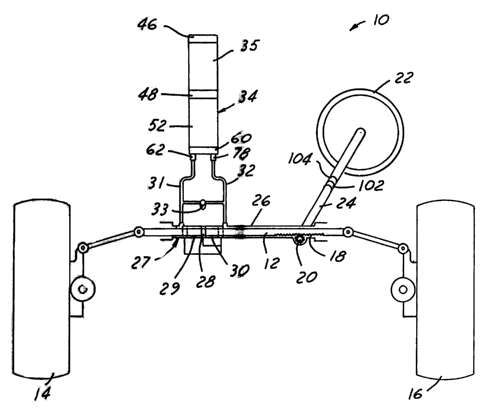
Refernng now more particularly to the drawings, FIG. 1 shows, in an exemplary
first system embodiment 10 of the invention, an elongated rack 12 adapted to
be connected at
opposite ends to the steerable wheels 14, 16 of a motor vehicle. The rack has
a series of teeth 18
along a section of its length. A rotatable pinion gear 20 in mesh with the
rack teeth 18 is
connected to a steering wheel 22 of the vehicle by a column 24 so as to
receive operator steering
input. (In many applications, there is an intermediate steering column or
shaft connected to
pinion gear 20 and shaft 24 by universal joints. This intermediate shaft is
not illustrated in the
schematic diagram of FIG. 1, and is not germane to the illustrated embodiments
of the present
invention.) Rack 12 extends lengthwise within an elongated housing 26, which
is constructed to
form an elongated power assist linear actuator cylinder 27 adjacent to one
end. Spaced apart
circular interior portions of reduced diameter define the ends of the cylinder
and have a sealed
engagement with the rack in order to close opposite ends of the cylinder. A
piston 28 carried by
the rack within cylinder 27 has a sealed engagement with the interior of the
cylinder and
separates the cylinder into cylinder chambers 29, 30 on opposite sides of the
piston. Hydraulic
fluid fills the chambers. A fluid line 31 communicates with one chamber 29
adjacent to one end
of the actuator cylinder. A fluid line 32 communicates with the other chamber
30 adjacent to the
opposite end of the cylinder. Fluid lines 31, 32 are connected to
corresponding ports of a power
assist module 34 in accordance with the present invention. A normally open
solenoid valve 33 is
connected between fluid lines 31, 32 for operation as will be described. In
the absence of an
electrical valve control signal, caused for example by an electrical control
unit or power failure,


CA 02398559 2002-07-24
WO 01/54960 PCT/USO1/02624
_j_
valve 33 will open so as to shore circaait module 34 and provide full manual
(non-assisted)
steering.
FIGS. 2-4 illustrate power assist module 34 in greater detail. Module 34
includes
an electric motor 35 having a stator 36 with associated stator windings, and a
rotor 38 having
associated radially extending poles. Motor 35 may be of any suitable type,
including a switched
reluctance motor, a brushless do motor, a brushed do motor and an ac motor. A
switched
reluctance motor is currently preferred. Rotor 38 in this embodiment is
secured to a leadscrew
40 by a coupling 39 or other suitable means such that rotor 38 and leadscrew
40 rotate coaxially
and in unison. The leadscrew is preferably press fitted and epoxied to the
rotor. The rotor and
leadscrew can alternatively be made as a single unit. Rotor 38 is supported at
opposite axial ends
by bearings 42, 44 carried by respective motor end bells 46, 48. Bearing 44 is
mounted within a
keeper 49. A resolver 50 or other suitable rotary position sensor is coupled
to the end of rotor 38
within end bell 46 (or end bell 48) for providing to control electronics a
signal indicative of
rotary position of the rotor and leadscrew shaft. Sensorless commutation may
also be employed
utilizing the stator windings as a position sensor.
A housing 52 is mounted on end bell 48. Housing 52 preferably is in the form
of
an elongated extrusion, as best seen in FIGS. 2 and 3, having a central
chamber 54 that is coaxial
in assembly with and surrounds leadscrew 40, and a plurality of peripheral
chambers surrounding
the central chamber. Being an extrusion, the central chamber and peripheral
chambers are of
uniform geometry throughout the length of the extruded housing body. A piston
56 is slidably
disposed within chamber 54 and has internal threads operatively coupled to the
external threads
of leadscrew 40. Thus, axial position of piston 56 with respect to leadscrew
40 is controlled by
rotation of the leadscrew, which in turn is controlled by rotation of rotor 38
within stator 36.
Chamber 54 and piston 56 are non-circular, preferably elliptical in lateral
cross section so that
piston 56 does not rotate within chamber 54 during rotation of leadscrew 40
and axial translation
of piston56 lengthwise of chamber 54. A port cap 60 is mounted on the end of
extrusion
housing 52 remote from end bell 48. Port cap 60 has a fluid port 62 connected
by a cross passage
64 (FIG. 3) to a central internal pocket 66, which aligns in assembly with
central chamber 54 of
extrusion 52. The end of chamber 54 on the opposing side of piston 56
communicates with a
central pocket 68 in end bell 48. Pocket 68 is connected by a cross passage 70
(FIG. 3) to a
pocket 72 that is aligned in assembly with a peripheral extrusion passage 74.
The opposing end
of passage 74 aligns with a pocket 76 in port cap 60, which is connected to a
fluid port 78. Thus,


CA 02398559 2002-07-24
WO 01/54960 PCT/USO1/02624
-6-
port 62 is in fluid communication with the working chamber formed on one side
of piston 56 by
means of cross passage 64, pocket 66 and chamber 54, and port 78 is in fluid
communication
with the working chamber on the opposing side of piston 56 by means of pocket
76, chamber 74,
pocket 72, cross passage 70 and pocket 68.
In assembly of module 34 with steering system 10 (FIG. 1), fluid lines 31, 32
are
connected to ports 62, 78 of port cap 60. A pair of pressure sensors 80, 82
are secured on port
cap 60 in fluid communication with the opposing sides of piston 56 in
extrusion 52. These
pressure sensors 80, 82 provided electrical pressure signals as a function of
fluid pressure within
fluid lines 31, 32 (FIG. 1). Fluid pressure in these lines varies not only as
a function of position
of piston 56 within extrusion 52, but also as a function of position of rack
12 under control of
steering wheel 22. A pair of gaskets 84, 86 are mounted between port cap 60
and end bell 48 and
the opposing ends of extrusion 52. A shaft seal 88 is mounted on the end of
leadscrew 40 within
port cap 60, and a second shaft seal 90 surrounds armature 38 within end bell
48. An electronic
controller 92 is disposed within a peripheral chamber 94 in extrusion 52. A
pair of openings 96
in one outside wall of extrusion 52 provide for electrical connection to
electronic controller 92
from outside module 34. An opening 97 in end bell 46 provides for electrical
connection to the
windings of motor 35, as best seen in FIG. 4. Piston 56 carries a magnetic 98
adjacent to the wall
99 of chamber 54 that separates chamber 54 from chamber 94. Electronic
controller 92 includes
a magnetic position sensor 100 disposed in assembly adjacent to wall 99.
Sensor 100 carries Hall
effect or other sensor elements responsive to magnetic energy from magnet 98
on piston 56 for
sensing the axial position of piston 56 along chamber 54 of extrusion ~2.
Inasmuch as piston 56
is non-rotatably mounted within chamber 54, magnetic 98 is continuously
positioned adjacent to
sensor 100. The mating threads of leadscrew 40 and piston ~6 are engineered
and fabricated to
provide smooth low friction operation with minimal leakage between the opposed
fluid
chambers. However, a small controlled leakage of fluid between the leadscrew
and the piston
may be desirable because the fluid would act as a lubricant between the
leadscrew and the piston.
A boundary layer of fluid would also aid in limiting backlash typically
associated with threaded
components.
A steering wheel position sensor 102 is operatively coupled to steering wheel
column 24 (FIG. 1 ) for providing an electrical signal indicative of absolute
position of the
steering wheel. This steering wheel position sensor may be monitored to
provide the following
steering wheel information: (a) the angular displacement in degrees (left or
right) from a center


CA 02398559 2002-07-24
WO 01/54960 PCT/USO1/02624
position, which is defined as the point where the steerable wheels are
straight ahead; (b) the rate
at which the steering wheel is being turned (measured in degrees per second,
for example). The
steering wheel position information from sensor 102 may be analyzed by
controller 92 and used
for: (a) initialization and positioning of piston 48 in the steering assist
module at the time of
vehicle start-up. (b) all steering maneuvers. The steering wheel position
information may be
used to calculate the required rpm of electric motor 35 for steering assist
operations. Steering
wheel position sensor 102 may be of any suitable type, such as an optical disk
and associated
sensors.
A torque sensor 104 (FIG. 1) is also coupled to steering column 24. During
vehicle operation, a measurable amount of torque is applied to steering column
24, either by the
vehicle operator through steering wheel 22 or in reaction to road forces
reflected back through
the steering gear of the vehicle into the system. This torque value reflected
in steering column 24
is affected by a number of factors including: (a) the coefficient of friction
between the vehicle
tires and the driving or road surface. This coefficient of friction in turn is
affected by: (1)
vehicle weight, (2) vehicle speed, and (3) driving surface conditions (e.g.,
dry pavement, surface
temperature, gravel, sand, water, ice); (b) friction between components of the
mechanical
steering system: ( 1 ) articulating joints (e.g., steering column universals,
bearings, tie-rod ends,
balljoint); (2) mating gear surfaces; (3) lubrication and contamination seals;
(c) continued
application of force to steering wheel after: ( 1 ) design travel limits of
steering system have been
met (i.e., full turn left or right); (2) contact with an external obstruction
(e.g., a curb or a rut in the
driving surface); (d) continued application of steering force to offset
external forces: ( 1 ) constant
radius turns (e.g., ramp onto freeway); (2) driving surfaces that pitched
perpendicular to direction
of travel (e.g., a crowned road). Data obtained from torque sensor 104 can be
used in
conjunction with data taken from pressure sensors 80, 82, and integrated to
determine and control
the magnitude of the torque output of motor 35 to be applied to develop the
hydraulic fluid
pressure to assist vehicle steering operations. This data can also be used to
differentiate between
operator input and road induced phenomena through suitable software systems in
controller 92.
FIG. 5 is a functional block diagram of electronic controller 92. Controller
92
includes a microprocessor-based motor control unit 106. Unit 106 receives an
input from piston
position sensor 100 through an associated interface circuit 108, an input from
steering column
position sensor 102 through an associated interface circuit 110, an input from
steering column
torque sensor 104 through an associated signal conditioning circuit 112, and
signals from


CA 02398559 2002-07-24
WO 01/54960 PCT/USO1/02624
_g_
pressure sensors 80, 82 through associated signal conditioning circuits 114,
116. A motor control
circuit 118 is connected to control unit 106 through a communication interface
120, and is
connected to motor 35 through an inverter circuit 122. Motor control circuit
118 receives
position feedback information from resolver 50 through a resolver signal
conditioning circuit 124
for closed loop servo control of motor rotation. Motor 35 also provides input
to motor control
unit 18 indicative of motor winding temperature through an associated
interface circuit 126.
Motor control unit 106 is connected to a reset and watchdog timer 128 for
monitoring continued
operation of the motor control unit, and is connected to other control units
on the vehicle through
an interface 130. Motor control unit 106 can obtain information indicative of
vehicle on/off
status and vehicle speed through interface 130. Control unit 106 provides a
valve control signal
output to solenoid valve 36 (FIG. 1 ) through a solenoid valve driver 132.
Controller 92 is
powered by the do power system of the vehicle through suitable voltage
regulation. In the
embodiment illustrated in FIG. l, rack 12 is directly coupled to steering
column 24, so steering
column position sensor 102 provides an indication of rack position. In other
applications, a
position sensor may be coupled to rack 12 for providing a direct indication of
absolute rack
position.
In operation, the vehicle operator provides a steering input to rack I 2 (FIG.
1 ) by
means of steering wheel 22, steering column 24 and pinion gear 20. Motion of
the rack, and
consequent motion of piston 30 within cylinder 28, creates a pressure
differential at lines 31, 32,
which is sensed by pressure sensors 80, 82. Electronic controller 92 receives
these pressure
signals, and provides a control signal to motor 35 so as to command rotation
of leadscrew 40 and
motion of piston 56 within chamber 54 to minimize this pressure differential
between the two
sensors. This electromotively developed motion of piston 56, and the
consequent hydraulically-
developed fluid flow forces, provide the power to assist the vehicle operator
in manually
applying torque through steering column 24 to achieve the desired motion at
rack 12 and move
steerable wheels 14, 16. When the vehicle is operated at relatively low speed,
it is important that
the power steering assist system be effective. Normally open solenoid valve 33
is closed by a
valve control signal from control unit 106, and assist module 34 is fully
effective. However, at
higher speeds, power assist is normally not needed. Under such circumstances,
a vehicle speed
sensor will provide appropriate input to motor control unit 106 through
vehicle bus interface 130,
whereupon control unit 106 will de-energize solenoid valve 33, opening the
valve and disabling
the power assistance. In an emergency situation, such as when the operator of
the vehicle makes


CA 02398559 2002-07-24
WO 01/54960 PCT/USO1/02624
-9-
a sudden lane change, a first indication of the steering maneuver is provided
by steering column
torque sensor 104. There is also a momentary increase in fluid pressure will
be sensed by
pressure sensors 80, 82, sending a signal to the controller to energize
solenoid valve 33 to close
the valve and allow power assistance. It is to be noted that use of a normally-
open solenoid valve
33 allows the rack and pinion steering arrangement to be effective, without
power assistance, in
the event of electrical power failure at the vehicle or failure at the power
assistance electrical
control unit.
FIGS. 6-8 illustrate a second embodiment 140 of the present invention.
Reference
numerals that are identical to those used in the embodiment of FIGS. 1-5
indicate identical or
functionally related parts. A power assist module 141 includes an electric
motor 142 having a
stator 144 and a rotatable armature 146. A sleeve 148 (FIG. 8) is press fitted
or otherwise
secured within armature 146 so as to rotate conjointly with the armature
within stator 144.
Sleeve 148 has internal threads mated with external threads on a leadscrew
150. Leadscrew 150
extends from both axial ends of motor 142. Armature 146 is rotatably mounted
between a pair of
end bells 152, 154 by means of bearings 156 rotatably supporting axially
opposed ends of sleeve
148. A resolver or other suitable rotary position sensor 158 is mounted within
a cap 159 secured
to end bell 156 and operatively coupled to sleeve 148 for detecting rotary
position of the sleeve.
A pair of end housings 160, 162 are mounted on end bells 152, 154 respectively
externally
coaxially surrounding the opposed ends of leadscrew 150. Housing 160 has an
internal chamber
164, within which is disposed a piston 166 operatively coupled to the
associated end of leadscrew
150. Likewise, housing 162 has an internal chamber 168, within which is
disposed a piston 170
operatively coupled to the associated opposite end of leadscrew 150. Thus,
rotation at armature
146 and sleeve 148 results in axial translation of leadscrew 150 and pistons
166, 170 within their
associated chambers 164, 168. The subassembly of pistons 166, 170 and
leadscrew 150 is
prevented from rotating with sleeve 148 by means of a pin 220 (FIGS. 8 and 9)
extending
through an anti rotation collar 220 secured to end bell 152, and an elongated
slot 224 (FIGS. 8-
10) in leadscrew 150.
The axially outer end of housing 160 terminates in a port cap 172 having a
fluid
passage 174 for connection to fluid line 31 or 32 (FIG. 1 ) through a fitting
175 (FIG. 7).
Likewise, housing 162 has a port cap 176 with a fluid passage 178 for
connection to the other
fluid line 31 or 32 (FIG. 1 ) through a fitting 179. Fluid pressure sensors
80, 82 are also mounted
on the port caps and connected to fluid passages 178, 174 respectively. Piston
170 has a magnet


CA 02398559 2002-07-24
WO 01/54960 PCT/USO1/02624
-10-
180 at its periphery adjacent to the internal wall of chamber 168. A magnetic
position sensor,
generally indicated at 182, is externally mounted on housing 162 for tracking
position of piston
170 within chamber 168. Sensor 182 includes a magnet 184 disposed within a non-
magnetic
keeper 186. Keeper 186 is slidably longitudinally captured between a pair of
sensor strips 188,
190. Keeper 186 has a pair of laterally extending wipers 226, 228 that
slidably engage strips 188,
190 respectively. Strips 188, 190 comprise variable resistance strips that
provide electrical
output signals indicative of position of keeper 186 and magnet 184 between the
strips. Strips
188, 190 are captured within a U-shaped housing 192, and a cover 194 is
positioned over housing
192 to form sensor assembly 182. Cover 194 is secured to port cap 176 and end
bell cap 159, as
best seen in FIG. 8. Piston 166 carnes a magnet 196, and a piston position
sensor 198 identical
to sensor 182 is mounted to housing 160 (FIGS. 7 and 8). Sensors 182, 198 are
connected to
motor control electronics 200 and system control electronics 202 (FIG. 6), as
are motor stator
144, pressure sensors 80, 82 and solenoid valve 33.
In operation, the embodiment of FIGS. 6-9 functions in a manner similar to
that of
the embodiment of FIGS. 1-5. Operator steering input to rack 12 produces a
pressure differential
between pressure sensors 80, 82. This pressure differential is sensed by the
control electronics,
which provide input to motor 142 for moving pistons 166, 170 conjointly in a
direction to reduce
such pressure differential. This piston movement assists the operator steering
input to the
steering system, as in the prior embodiment. FIG. 6 also illustrates that the
electro-hydraulic
actuator system in accordance with the present invention may receive external
control input not
only from a steering wheel or yoke 204 associated with a vehicle steering
system, but also from a
joystick 206, a geographic positioning system 208 and/or a voice input command
module 210.
As indicated previously, the electronic control unit may be connected through
vehicle bus interface 130 (FIG. 5) to as conventional multiplexed vehicle
information network.
On/off vehicle input information and vehicle speed information may be obtained
from the vehicle
information network. There may be a bidirectional exchange of system data over
the vehicle
network, so that the system control electronics may share with a conventional
vehicle onboard
electronic control unit the power steering system status, pressure data,
actuator sensor data, etc.
System performance can then be monitored by suitable software, system
diagnostics can be
analyzed by suitable software, and system performance can be enhanced by
changes in such
software. Both illustrated embodiments of the invention show use in a power-
assisted vehicle
steering system, in which the hydraulic actuator is double-ended and
integrated with an otherwise


CA 02398559 2002-07-24
WO 01/54960 PCT/USO1/02624
-11-
conventional rack and pinion steering arrangement for connection to opposed
steerable vehicle
wheels. However, the hydraulic actuator could be single-ended or a rotary-type
actuator without
departing from the principles of the invention in their broadest aspects.
There has thus been disclosed an electro-hydraulic actuator system that fully
satisfies all of the objects and aims previously set forth. The invention has
been disclosed in
conjunction with electro-hydraulic power-assisted vehicle steering systems,
but fords ready
application in other system applications as described. As applied specifically
to power steering
systems, elimination of the conventional rotary pump removes a major source of
fluid-borne
noise and improves fuel economy on the order of four to seven percent. A
number of
modifications and variations have been discussed. Other modifications and
variations will
readily suggest themselves to persons of ordinary skill in the art in view of
the foregoing
description. The invention is intended to embrace all such modifications and
variations as fall
within the spirit and broad scope of the appended claims.

Representative Drawing
A single figure which represents the drawing illustrating the invention.
Administrative Status

For a clearer understanding of the status of the application/patent presented on this page, the site Disclaimer , as well as the definitions for Patent , Administrative Status , Maintenance Fee  and Payment History  should be consulted.

Administrative Status

Title Date
Forecasted Issue Date Unavailable
(86) PCT Filing Date 2001-01-26
(87) PCT Publication Date 2001-08-02
(85) National Entry 2002-07-24
Dead Application 2007-01-26

Abandonment History

Abandonment Date Reason Reinstatement Date
2006-01-26 FAILURE TO REQUEST EXAMINATION
2007-01-26 FAILURE TO PAY APPLICATION MAINTENANCE FEE

Payment History

Fee Type Anniversary Year Due Date Amount Paid Paid Date
Application Fee $300.00 2002-07-24
Maintenance Fee - Application - New Act 2 2003-01-27 $100.00 2003-01-02
Registration of a document - section 124 $100.00 2003-02-06
Maintenance Fee - Application - New Act 3 2004-01-26 $100.00 2003-12-31
Maintenance Fee - Application - New Act 4 2005-01-26 $100.00 2004-12-31
Maintenance Fee - Application - New Act 5 2006-01-26 $200.00 2006-01-03
Registration of a document - section 124 $100.00 2008-08-25
Owners on Record

Note: Records showing the ownership history in alphabetical order.

Current Owners on Record
BOSCH REXROTH CORPORATION
Past Owners on Record
BOSCH REXROTH CORPORATION
SPADAFORA, WILLIAM GLENN
Past Owners that do not appear in the "Owners on Record" listing will appear in other documentation within the application.
Documents

To view selected files, please enter reCAPTCHA code :


To view images, click a link in the Document Description column. To download the documents, select one or more checkboxes in the first column and then click the "Download Selected in PDF format (Zip Archive)" or the "Download Selected as Single PDF" button.

List of published and non-published patent-specific documents on the CPD .

If you have any difficulty accessing content, you can call the Client Service Centre at 1-866-997-1936 or send them an e-mail at CIPO Client Service Centre.


Document
Description 
Date
(yyyy-mm-dd) 
Number of pages   Size of Image (KB) 
Representative Drawing 2002-07-24 1 14
Cover Page 2002-12-09 1 48
Claims 2002-07-24 14 626
Abstract 2002-07-24 1 69
Drawings 2002-07-24 7 220
Description 2002-07-24 11 667
PCT 2002-07-24 5 219
Assignment 2002-07-24 3 100
Correspondence 2002-12-05 1 24
Fees 2003-01-02 1 34
Assignment 2003-02-06 6 311
PCT 2002-07-25 3 135
Fees 2003-12-31 1 34
Fees 2004-12-31 1 28
Fees 2006-01-03 1 27