Note: Descriptions are shown in the official language in which they were submitted.
CA 02398715 2002-07-29
WO 01/63089 PCT/US00/10116
-1 _
SEQUENTL~1I. HYDRAULIC CONTROL SYSTEM
FOR USE IN A SUETERRANEAN WELL
BACKGROUND OF THE INVENTION
The present invention relates generally to operations performed
in conjunction with subterranean wells and, in an embodiment
described herein, more particularly provides a hydraulic well control
system.
It is very advantageous to be able to independently control well
tools from the earth's surface, or other remote location. For example,
production from one of several zones intersected by a well may be halted ,
due to water invasion, while production continues from the other zones.
Alternatively, one zone may be in communication with a production
tubing string, while the other zones are shut in.
In order to control multiple downhole well tools, various systems
have been proposed and used. One type of system utilizes electrical
signals to select from among multiple well tools for operation of the
CA 02398715 2002-07-29
WO 01/63089 PCT/US00/10116
-2 -
selected tool or tools. Another type of system utilizes pressure pulses on
hydraulic lines, with the pulses being counted by the individual tools, to
select particular tools for operation thereof.
Unfortunately, these systems suffer from fundamental
disadvantages. The systems which use electrical communication or
power to select or actuate a downhole tool typically have temperature
limitations or are prone to conductivity and insulation problems,
particularly where integrated circuits are utilized or connectors are
exposed to well fluids. The systems .which use pressure pulses are
typically very complex and, therefore, very expensive and susceptible
to failure.
From the foregoing, it can be seen that it would be quite desirable
to provide a well control system which does not use electricity or
complex pressure pulse counting mechanisms, but which provides a
reliable, simple and cost effective means of controlling downhole tools. It
is accordingly an object of the present invention to provide such a well
control system and associated methods of controlling well tools.
SUMMARY OF THE INVENTION
In carrying out the principles of the present invention, in
accordance with an embodiment thereof, a well control system is
provided which utilizes hydraulic lines to select one or more well tools
for operation thereof, and which utilizes hydraulic lines to actuate the
selected well tool(s). The use of electricity downhole is not required, nor
is use of complex pressure pulse decoding mechanisms required.
Instead, the digital hydraulic well control system utilizes a sequential
combination of pressure levels on the hydraulic lines to select a well tool
for actuation, and uses pressure in one or more hydraulic lines to
3 0 actuate the tool.
CA 02398715 2002-07-29
WO 01/63089 PCT/US00/10116
-3 -
In one aspect of the present invention, a method of hydraulically
controlling multiple well tools in a well is provided. A set of hydraulic
lines is interconnected to each of the tools. At least one of the tools is
selected for actuation thereof by generating a fluid pressure on a
combination of the hydraulic lines in a predetermined sequence in
which the fluid pressure is applied successively to selected ones of the
combination of hydraulic lines.
The tool is not selected for operation thereof if either the pressure
is applied to an inappropriate one of the hydraulic lines, or the pressure
is applied to the proper hydraulic lines, but in the wrong sequence.
Pressure pulse counting is not used.
The hydraulic lines are connected to an actuation control device
of a well tool assembly, which also includes an actuator and a well tool
operated by the actuator. When one or more of the control devices
receives the correct sequence of pressure applications to the appropriate
combination of the hydraulic lines, the control device permits fluid
communication between certain of the hydraulic lines and the actuator.
Fluid pressure from one or more of these hydraulic lines may then be
used in the actuator to operate the tool. Preferably, the actuator is
pressure balanced until these hydraulic Iines are placed in fluid
communication with the actuator.
The actuation control device includes a sequence detecting
mechanism which places one or more hydraulic inputs to the control
device in fluid communication with one or more hydraulic outputs of
the control device when an appropriate sequence of pressure
applications is received at the hydraulic inputs. Preferably, the
hydraulic outputs are in fluid communication with each other until the
appropriate sequence of pressure applications is received.
In another aspect of the present application, the actuation control
device may also serve as an actuator. It may include an actuator
member which is displaced when the sequence detecting mechanism
CA 02398715 2002-07-29
WO 01/63089 PCT/US00/10116
-4 -
detects that an appropriate sequence of pressure applications is received
at hydraulic inputs of the device.
These and other features, advantages, benefits and objects of the
present invention will become apparent to one of ordinary skill in the
art upon careful consideration of the detailed description of
representative embodiments of the invention hereinbelow and the
accompanying drawings.
BRIEF DESCRIPTION OF THE DRAWINGS
FIG.1 is a schematic view of a method embodying principles of the
present invention;
FIG. 2 is a schematic cross-sectional view of a well tool that may
be used in the method of FIG.1;
FIG. 3 is a hydraulic schematic of a first well control system
embodying principles of the present invention;
FIG. 4 is a hydraulic schematic of a second well control system
embodying principles of the present invention;
FIG. 5 is a hydraulic schematic of a third well control system
embodying principles of the present invention;
FIG. 6 is a hydraulic schematic of a fourth well control system
embodying principles of the present invention;
FIG. 7 is a schematic partially cross-sectional view of an actuation
control device embodying principles of the present invention;
FIGS. 8A-C are a hydraulic schematic of a fifth well control
system embodying principles of the present invention; and
FIGS. 9A&B are schematic partially cross-sectional views of
successive axial sections of another actuation control device embodying
principles of the present invention.
CA 02398715 2002-07-29
WO 01/63089 PCT/US00/10116
_r~_
DETAILED DESCRIPTION
Representatively illustrated in FIG. t is a method 10 which
embodies principles of the present invention. In the following
description of the method 10 and other apparatus and methods
described herein, directional terms, such as "above", "below", "upper",
"lower", "right", "left", etc., are used only for convenience in referring to
the accompanying drawings. Additionally, it is to be understood that
the various embodiments of the present invention described herein m a y
be utilized in various orientations, such as inclined, inverted,
horizontal, vertical, etc., and in various configurations, without
departing from the principles of the present invention.
In the method 10 as depicted in FIG. 1, four subterranean zones
12, 14, 16, 18 are intersected by a wellbore 20. The following
description of the method 10 assumes that it is desired to produce fluid to
the earth's surface from one or more of the zones 12, 14, 16, 18 via a
production tubing string 22. However, it is to be clearly understood
that the principles of the present invention are not limited to production
wells, production from multiple zones, or any of the specific details of the
method 10 as described herein. For example, principles of the present
invention may be used in injection wells, in wells where fluid flow from,
or into, a single formation is to be controlled, in methods where an
aspect of the well other than fluid flow is to be controlled, etc. Thus, the
method 10 is described herein as merely an example of the wide variety
of uses for the principles of the present invention.
The production tubing string 2 2 as depicted in FIG. 1 includes
four well tool assemblies 24, 26, 28, 30. The tubing string 22 also
includes packers 32, 34, 36, 38, 40 isolating the zones 12, 14, 16, 18
from each other and from portions of the wellbore 20, according to
conventional practice. Representatively, the tool assemblies 24, 26, 28,
CA 02398715 2002-07-29
WO 01/63089 PCT/US00/10116
-6 -
30 are valve assemblies used to permit or prevent fluid flow between the
zones 12, 14, 16, 18 and the interior of the tubing string 22, but it is to
be clearly understood that the tool assemblies could include other types
ofwell tools, such as chokes, injectors, instruments, etc.
To permit production of fluid from zone 12, valve assembly 24 is
opened, thereby permitting fluid communication between the tubing
string 22 and the wellbore 20 between packers 32 and 34. To prevent
production of fluid from zone 12, valve assembly 24 is closed, thereby
preventing fluid communication between the tubing string 22 and the
wellbore 20 between packers 32 and 34. Similarly, the other valve
assemblies 26, 28, 30 may be used to permit or prevent production of
fluid from the respective zones 14, 16, 18 .
Actuation of the valve assemblies 24, 26, 28, 30 is accomplished
by means of hydraulic lines 42 interconnected to each of the valve
assemblies. The hydraulic lines 42 extend to the earth's surface, or
another remote location, where fluid pressure on each of the lines m a y
be controlled using conventional pumps, valves, accumulators,
computerized controls, etc. In one important aspect of the present
invention, one or more of the lines 42 may also be used to select one or
more of the valve assemblies 24, 26, 28, 30 for actuation thereof.
Each of the valve assemblies 24, 26, 28, 30 includes an
addressable control device 44, an actuator 46 and a valve 48 or other
well tool. The hydraulic lines 42 are interconnected to each of the
control devices 44. Each of the control devices 44 has at least one
address, and multiple ones of the control devices may have the same
address. When a combination of pressure levels on certain ones of the
hydraulic lines 42 matches an address of one of the control devices 44,
the corresponding valve assembly 24, 26, 28 and/or 30 is selected for
actuation thereof.
When a valve assembly 24, 26, 28 and/or 30 is selected, fluid
pressure on one or more of the hydraulic lines 42 may then be used to
CA 02398715 2002-07-29
WO 01/63089 PCT/US00/10116
_7 _
actuate the selected assembly or assemblies. Thus, the method 10 does
not require the use of electricity downhole to select or actuate any of the
valve assemblies 24, 26, 28 or 30, and does not require a series of
pressure pulses to be decoded at each of the assemblies. Instead, the
method 10 is performed conveniently and reliably by merely
generating a combination of pressure levels on certain ones of the
hydraulic lines 42 to address the desired control devices) 44, and
utilizing fluid pressure on one or more of the hydraulic lines to actuate
the corresponding selected well tools) 48. The specific hydraulic lines
used to select the tool assembly or assemblies for actuation thereof m a y
or may not also be used to actuate the selected assembly or assemblies.
Referring additionally now to FIG. 2, a valve assembly 50 is
schematically and representatively illustrated. The valve assembly 50
may be used for one of the tool assemblies 24, 26, 28, 30 in the method
10. Of course, other valve assemblies and other types of tool assemblies
may be used in the method 10, and the valve assembly 50 may be
configured differently from that shown in FIG. 2, without departing
from the principles of the present invention.
The valve assembly 50 includes a valve portion 52 which is of the
type well known to those skilled in the art as a sliding sleeve valve.
Thus, the valve portion 52 includes an inner sleeve 54 which is
displaced upwardly or downwardly to thereby permit or prevent fluid
flow through ports 56 formed radially through an outer housing 58.
The housing 58 may be interconnected in the tubing string 22 of the
method 10 by, for example, providing appropriate conventional threads
thereon.
The sleeve 54 is caused to displace by fluid pressure in an actuator
portion 60 of the valve assembly 50. The actuator portion 60 includes a
part of the sleeve 54 which has a radially enlarged piston 62 formed
thereon. The piston 62 reciprocates within a radially enlarged bore 6 4
formed in the housing 58. The piston 62 separates an upper chamber
CA 02398715 2002-07-29
WO 01/63089 PCT/US00/10116
_$_
64 from a lower chamber 66, with the chambers being formed radially
between the sleeve 54 and the housing 58.
On the left side of FIG. 2, the valve assembly 50 is depicted with
the sleeve 54 in its upwardly displaced position, permitting fluid flow
through the ports 56. On the right side of FIG. 2, the valve assembly 50
is depicted with the sleeve 54 in its downwardly displaced position,
preventing fluid flow through the ports 56. It will be readily
appreciated by one skilled in the art that the sleeve 54 is biased to its
upwardly displaced position by fluid pressure in the lower chamber 6 6
exceeding fluid pressure in the upper chamber 64. Similarly, the sleeve
54 is biased to its downwardly displaced position by fluid pressure in the
upper chamber 64 exceeding fluid pressure in the lower chamber 6 6 .
Fluid pressure in the chambers 64, 66 is controlled, at least in
part, by an addressable actuation control device 68. The control device
68 is in fluid communication with the chambers 64, 66 using passages
70. Additionally, the control device 68 is interconnected to external
hydraulic lines 72. ~ When used in the method 10, the valve assembly
50 may be one of multiple well tool assemblies with corresponding
control devices 68 interconnected to the hydraulic lines 72 .
The control device 68 functions to permit fluid communication
between the passages 70 and certain ones of the hydraulic lines 7 2
when a code or address is present on the hydraulic lines, which code
corresponds to an address of the control device. The term "code" is used
herein to indicate a combination of pressure levels on a set of hydraulic
lines. For example, 1,000 psi may be present on certain ones of the
hydraulic lines 72, and 0 psi may be present on others of the hydraulic
lines to thereby transmit a particular code corresponding to an address
of the control device 68.
Preferably, the pressure levels are static when the code is
generated on the hydraulic lines 72, however, it is recognized that, due
to the long distances which may be involved in positioning well tools in
CA 02398715 2002-07-29
WO 01/63089 PCT/US00/10116
-9 -
wells, the fact that a desired fluid pressure may not be instantly
generated on a given hydraulic line, etc., a period of time is required to
generate the code on the hydraulic lines. Nevertheless, it will be readily
appreciated by one skilled in the art that this method of transmitting a
code or address via the hydraulic lines 72 is substantially different, and
far easier to accomplish, as compared to applying a series of pressure
pulses on a hydraulic line. In the latter case, for example, pressure on a
hydraulic line is intentionally increased and decreased repeatedly, and
a code or address is not generated on multiple hydraulic lines, but is
instead generated on a single hydraulic line.
Referring additionally now to FTG. 3, a well control system
hydraulic schematic is representatively illustrated. The schematic
depicts three addressable actuation control devices 74, 76, 78 utilized to
control actuation of three corresponding well tools 80, 82, 84 via
respective actuators 86, 88, 90. The well tools 80, 82, 84 may be
valves, such as valve 52 or valves 48 in the method 10, or they may be
another type of well tool. The actuators 86, 88, 90 may be similar to
the actuator 60 of the valve assembly 50, and may be used for the
actuators 46 in the method 10, or they may be differently configured.
Similarly, the control devices 74, 76, 78 may correspond to the control
device 68 or the control devices 44 in the method 10.
The hydraulic schematic shown in FIG. 3 is described herein as an
example of the manner in which the principles of the present invention
provide convenient, simple and reliable control over the operation of
multiple well tool assemblies in a well. However, it is to be clearly
understood that principles of the present invention may be incorporated
into other methods of controlling well tools and, demonstrating that
fact, alternate hydraulic schematics are illustrated in FIGS. 4-6 and are
described below. Therefore, it may be seen that the descriptions of
specific hydraulic schematics herein are not to be taken as limiting the
principles of the present invention.
CA 02398715 2002-07-29
WO 01/63089 PCT/US00/10116
-10-
The hydraulic schematic of FIG. 3 demonstrates a manner in
which three hydraulic lines (labelled A, B and C in the schematic) may
be used in controlling actuation of multiple downhole well tools 80, 8 2,
84. For the purpose of this example, each of the control devices 74, 76,
78 has been configured to have two addresses. The control device 7 4
has addresses 001 and 010, the control device 76 has addresses 011 and
100, and the control device 78 has addresses 101 and 110. It will be
readily appreciated that these addresses are similar to the type of
notation used in digital electronics and sometimes referred to as binary
code. In binary code, 1's and 0's are used to refer to the presence or
absence of voltage, a state of charge, etc. on elements of an electronic
device. In the present description of the hydraulic schematic, the 1's
and 0's are used to indicate the presence or absence of a predetermined
pressure level on a hydraulic line.
Using one of the addresses, 001, of the control device 74 as an
example, the first 0 refers to the absence of the pressure level on
hydraulic line A. The second 0 refers to the absence of the pressure level
on hydraulic line B. The 1 refers to the presence of the pressure level on
hydraulic line C. Therefore, the control device 74 is addressed or
selected for control of actuation of the tool 80 by generating the code
001 on the hydraulic lines A, B, C (i.e., the absence of the pressure level
on lines A and B, and the presence of the pressure level on line C).
Note that the control device 74 as depicted in FIG. 3 has two
addresses, 0 01 and 010. The use of multiple addresses in the control
device 74 permits the use of multiple ways of actuating the tool 80. For
example, if the tool 80 is a valve, address 001 may be used to open the
valve, and address 010 may be used to close the valve. Of course, more
than one of the control devices 74, 76, 78 could have the same address.
For example, each of the control devices 74, 7&, 78 could have the
address 001, so that when this code is generated on the hydraulic Iines
A, B, C, each of the tools 80, 82, 84 is selected for actuation in the same
manner. If the tools 80, 82, 84 are all valves, for example, the code 001
CA 02398715 2002-07-29
WO 01/63089 PCT/US00/10116
-11-
generated on the hydraulic lines A, B, C could select each of the control
devices 74, 76, 78 so that all of the valves are to be closed.
For convenience in the further description of the hydraulic
schematic depicted in FIG. 3, the tools 80, 82, 84 are assumed to be
valves and the predetermined pressure level corresponding to a "1" in
the control device addresses is assumed to be 1,000 psi. However, it is to
be clearly understood that the tools 80, 82, 84 are not necessarily
valves, and the predetermined pressure level may be other than 1,000
psi, without departing from the principles of the present invention.
Using these assumptions and the addresses shown in FIG. 3, the
following table is given as an example of the manner in which actuation
of the valves 80, 82, 84 may be selected using the addresses:
Address Actuation
A B C
0 0 1 Open Valve 8 0
0 1 0 Close Valve 8 0
0 1 1 Open Valve 8 2
1 0 0 Close Valve 8 2
1 0 1 Open Valve 8 4
2 0 1 1 0 Close Valve 8 4
From the above, it may be readily appreciated that all of the
valves 80, 82, 84 may be easily selected for actuation to either a closed
or open configuration by merely generating a predetermined pressure
level, such as 1,000 psi, on certain ones of the hydraulic lines A, B, C.
Furthermore, each of the above addresses is unique, so that only one of
the valves is selected for actuation at one time, thereby permitting
independent control of each of the valves 80, 82, 84. However, as noted
above, it may be desired to have multiple ones of the valves 80, 82, 84
CA 02398715 2002-07-29
WO 01/63089 PCT/US00/10116
-12-
selected for actuation at a time, in which case, the appropriate control
devices would be configured to have the same address.
The hydraulic schematic of FIG. 3 graphically demonstrates one
.of the advantages of the present method over prior hydraulic control
methods. That is, relatively few simple conventional hydraulic
components are used to control actuation of multiple well tools, without
the need for complex unreliable mechanisms or electricity. As
illustrated in FIG. 3, only check valves, relief valves and pilot operated
valves, which are described in further detail below, are used in the
control devices 74, 76, 78.
Control device 74 includes check valves 92, 94, relief valves 96,
98, and normally open conventional pilot operated valves 100, 102,
104, 106. Dashed lines are used in FIG. 3 to indicate connections
between the hydraulic lines A, B, C and pilot inputs of the pilot operated
valves. For example, hydraulic line A is connected to the pilot inputs of
the pilot operated valves 10 2 and 10 6. The pilot operated v aloes 10 0,
102, 104, 106 are configured so that, when the predetermined pressure
level is on the corresponding hydraulic line connected to its pilot input,
the valve is operated. Thus, when the predetermined pressure level is
2 0 on hydraulic line A, valves 10 2 and 10 6 open; when the predetermined
pressure level is on hydraulic line B, valve 100 opens; and when the
predetermined pressure level is on hydraulic line C, valve 104 opens.
Of course, if one of the valves 100, 102, 104, 106 is a normally open
valve, then the valve would close when the predetermined pressure
level is at its pilot input.
To select the valve 80 for actuation to an open configuration, the
code 001 is generated on the hydraulic lines A, B, C by generating the
predetermined pressure level, 1,000 psi, on hydraulic line C. Note that
pilot operated valves 10 0 and 10 2 remain open, since pressure is not
3 0 applied to hydraulic lines A and B, and the pressure on hydraulic line C
CA 02398715 2002-07-29
WO 01/63089 PCT/US00/10116
_13_
is transmitted through those pilot operated valves and through check
valve 92 to a passage 108 leading to the actuator 86.
The pressure on hydraulic line C is, thus, applied to one side of a
piston in the actuator 86. The other side of the actuator 86 piston is
connected via a passage 110 to the control device 74. Note that the
passages 108, 110 are analogous to the passages 70 of the valve
assembly 50 depicted in FIG. 2 .
Fluid pressure in passage 110 is not transmitted through the
control device 74 to the hydraulic line B, however, unless the pressure
is great enough to be transmitted through the relief valve 98, due to the
fact that pilot operated valve 104 is closed (because the predetermined
fluid pressure is on hydraulic line C). Therefore, the actuator 86 piston
is not permitted to displace unless fluid pressure in the passage 110 is
great enough to be transmitted through'the relief valve 98. Preferably,
the relief valve 98 is configured so that it opens at a pressure greater
than the predetermined fluid pressure used to transmit the code to the
control devices 74, 76, 78. For example, if the predetermined fluid
pressure is 1,000 psi, then the relief valve 98 may be configured to open
at 1,500 psi. Thus, transmission of the code 001 to the control device 7 4
selects the valve 80 for actuation thereof, but does not result in the
valve being actuated.
To actuate the valve 80 after the code 001 has been transmitted
via the hydraulic lines A, B, C to the control device 74, fluid pressure on
the hydraulic line C is increased above the predetermined fluid
pressure. The increased fluid pressure is transmitted through the relief
valve 98 and to the hydraulic line B, thereby permitting displacement
of the actuator 86 piston. Displacement of the actuator 86 piston causes
the valve 80 to open. Alternatively, the increased fluid pressure could
be transmitted through the relief valve 98 and discharged into the well.
To recap the sequence of steps in opening the valve 80, the code
001 is generated on the hydraulic lines A, B, C (the predetermined fluid
CA 02398715 2002-07-29
WO 01/63089 PCT/US00/10116
_14_
pressure existing only on hydraulic line C), and then fluid pressure on
hydraulic line C is increased to open the valve.
The procedure is very similar to close the valve 80. The code 010
is generated on the hydraulic lines A, B, C (the predetermined fluid
pressure existing only on hydraulic line B), thereby closing pilot
operated valve 100, with pilot operated valves 102, 104 and 106
remaining open, and then fluid pressure on hydraulic line B is increased
to close the valve. In the case of closing the valve 80, the fluid pressure
on hydraulic line B is increased to permit its transmission through the
relief valve 96 to hydraulic line C. Thus, the hydraulic lines A, B, C are
used both to select the valve 80 for actuation thereof, and to supply fluid
pressure to perform the actuation.
Note that, if any other codes are generated on the hydraulic lines
A, B, C, the valve 80 is not selected for actuation thereof. For example,
if the predetermined fluid pressure is generated on hydraulic line A,
pilot operated valves 10 2 and l0 6 will close, preventing displacement of
the actuator 86 piston. The pilot operated valves 100, 102, 104, 10 6
are configured, and their pilot inputs connected to appropriate ones of
the hydraulic lines A, B, C, so that the valve 80 is selected for actuation
2 0 thereof only when the correct code has been generated on the lines.
The control device 76 includes check valves 112, 114, relief
valves 116, 118, normally open pilot operated valves 120, 122, 124,
and normally closed pilot operated valve 126. The control device 7 6
has addresses 011 and 100 for opening and closing the valve 82, and its
operation is similar to the operation of the control device 74 described
above. When the code 011 is present on the hydraulic lines A, B, C (i.e.,
the predetermined pressure level is on lines B & C, but not on line A),
pilot operated valves 120, 126 are open, permitting fluid pressure in
hydraulic line B to be transmitted to the actuator 88. When the fluid
pressure exceeds the opening pressure ofthe relief valve 118 (e.g., 1,500
psi), it is transmitted to hydraulic line A and the valve 82 is opened.
CA 02398715 2002-07-29
WO 01/63089 PCT/US00/10116
_15_
When the code 100 is present on the hydraulic lines A, B, C, pilot
operated valves 122, 124 are open, permitting fluid pressure in
hydraulic line A to be transmitted to the actuator 88. When the fluid
pressure exceeds the opening pressure of the relief valve 116, it is
transmitted to hydraulic line B and the valve 82 is closed.
The control device 78 includes check valves 128, 130, relief
valves 132, 134, normally open pilot operated valves 136, 138, and
normally closed pilot operated valves 140, 142. The control device 7 8
has addresses 101 and 110 for opening and closing the valve 84. When
the code 101 is present on the hydraulic Iines A, B, C (i.e., the
predetermined pressure level is on lines A & C, but not on line B), pilot
operated valves 136, 140 are open, permitting fluid pressure in
hydraulic line C to be transmitted to the actuator 90. When the fluid
pressure exceeds the opening pressure of the relief valve 134 (e.g.,1,500
psi), it is transmitted to hydraulic line B and the valve 84 is opened.
When the code 110 is present on the hydraulic lines A, B, C, pilot
operated valves 138, 142 are open, permitting fluid pressure in
hydraulic line B to be transmitted to the actuator 90. When the fluid
pressure exceeds the opening pressure of the relief valve 132, it is
transmitted to hydraulic line C and the valve 84 is closed.
The above description of the well control system embodiment of
the present invention depicted in FIG. 3 illustrates the ease with which
multiple tool assemblies may be controlled using digital hydraulics. In
this example, valves 80, 82, 84 are either opened or closed, depending
upon the pressure levels on the hydraulic lines A, B, C. However, it is to
be clearly understood that the principles of the present invention m a y
be used to perform other functions, such as to vary the configuration of
a well tool. For example, the valve 80 could instead be a downhole
choke and the level of pressure applied to the choke via the passages
180, 110 could be used to regulate the rate of fluid flow through the
choke.
CA 02398715 2002-07-29
WO 01/63089 PCT/US00/10116
-16-
Referring additionally now to FIG. 4, another well control system
hydraulic schematic embodying principles of the present invention is
representatively illustrated. The hydraulic schematic shown in FIG. 4
is similar in many respects to the hydraulic schematic shown in FIG. 3,
but is different in at least two aspects, in that there are seven actuators
144, 14.6, 148, 150, 152, 154, 156 controlled by respective control
devices 158, 160, 162, 164, 166, 168, 170, and in that there are four
hydraulic lines A, B, C, D instead of three. Note that well tools actuated
by the actuators 144, 146, 148, 150, 152, 154, 156 are not shown in
FIG. 4, but it is to be understood that in actual practice a well tool is
connected to each of the actuators as described above.
It will be readily appreciated by one skilled in the art that the use
of an additional hydraulic line D permits the control of additional well
tools, or the use of additional functions with fewer well tools, due to the
fact that additional distinct digital hydraulic codes may be on the
hydraulic lines. For the example illustrated in FIG. 4, the following
table shows the manner in which the actuators 144, 146, 148, 150,
152, 154, 156 may be selected using the addresses:
Address Actuation
A B C D
0 0 0 1 Displace Actuator 144 Piston to the Right
0 0 1 0 Displace Actuator 144 Piston to the Left
0 0 1 1 Displace Actuator 14 6 Piston to the Right
0 1 0 0 Displace Actuator 14 6 Piston to the Left
0 1 0 1 Displace Actuator 148 Piston to the Right
0 1 1 0 Displace Actuator 148 Piston to the Left
0 1 1 1 Displace Actuator 150 Piston to the Right
1 0 0 0 Displace Actuator 150 Piston to the Left
1 0 0 1 Displace Actuator 152 Piston to the Right
CA 02398715 2002-07-29
WO 01/63089 PCT/US00/10116
-17-
1 0 1 0 Displace Actuator 152 Piston to the Left
1 0 1 1 Displace Actuator 154 Piston to the Right
1 1 0 0 Displace Actuator 154 Piston to the Left
1 1 0 1 Displace Actuator 15 6 Piston to the Right
1 1 1 0 Displace Actuator 156 Piston to the Left
Of course, displacement of an actuator piston to the right may be
used to open a valve and displacement of an actuator piston to the left
may be used to close a valve, as described above, or the piston
displacements may be used for other purposes or in controlling other
types of well tools. Additionally, note that each control device 158, 160,
162, 164, 166, 168, 170 has two distinct addresses, but in practice
more than one control device may have the same address, a control
device may have a number of addresses other than two, etc.
Operation of the well control system of FIG. 4 is very similar to
operation of the well control system of FIG. 3 described above.
Therefore, only the operation of the control device 158 will be described
in detail below, it being understood that the other control devices 160,
162, 164, 166, 168, 170 are operated in very similar manners, which
will be readily apparent to one skilled in the art.
The control device 158 includes check valves 172, 174, relief
valves 176, 178 and normally open pilot operated valves 180, 182,
184, 186, 188, 190. The control device 158 has addresses 0101 and
0110 for operating the actuator 144. When the code 0101 is present on
the hydraulic lines A, B, C, D (i.e., the predetermined pressure level is
on lines B & D, but not on lines A or C), pilot operated valves 18 0, 18 2,
184 are open, permitting fluid pressure in hydraulic line D to be
transmitted to the actuator 144. When the fluid pressure exceeds the
opening pressure of the relief valve 178 (e.g., 1,500 psi), it is
transmitted to hydraulic line C and the actuator 144 piston is displaced
CA 02398715 2002-07-29
WO 01/63089 PCT/US00/10116
-18-
to the right. When the code 0110 is present on the hydraulic Iines A, B,
C, D, pilot operated valves 186, 188, 190 are open, permitting fluid
pressure in hydraulic line C to be transmitted to the actuator 144.
When the fluid pressure exceeds the opening pressure of the relief valve
176, it is transmitted to hydraulic line D and the actuator 144 piston is
displaced to the left.
Thus, the well control system of FIG. 4 demonstrates that any
number of hydraulic lines may be utilized to control any number of well
tool assemblies, without departing from the principles of the present
invention.
Referring additionally now to FIG. 5, another well control system
hydraulic schematic is representatively illustrated. The well control
system of FIG. 5 is similar in many respects to those depicted in FIGS. 3
& 4 and described above, but differs in at least two substantial aspects in
that the hydraulic lines used to select well tool assemblies for actuation
thereof are not the same as the hydraulic lines used to deliver fluid
pressure to the actuators, and in that each control device has only one
address.
The well control system of FIG. 5 utilizes three hydraulic lines A,
B, C to select from among eight control devices 192, 194, 19~, 198,
200, 202, 204, 206 for actuation of eight respective actuators 208,
210, 212, 214, 216, 218, 220, 222. As with the well control system of
FIG. 4 described above, well tools are not shown in FIG. 5, it being
understood that the actuators 208, 210, 212, 214, 216, 218, 220, 2 2 2
are connected to well tools in actual practice.
Note that the control devices 192, 194, 196, 198, 200, 202, 204,
206 as depicted in FIG. 5 do not include relief valves and, thus, are
somewhat less complex as compared to the well control systems of FIGS.
3 & 4. This is due to the fact that there is no need to discriminate in the
control devices 192, 194, 196, 198, 200, 202, 204, 206 between the
predetermined pressure level needed to address one or more of the
CA 02398715 2002-07-29
WO 01/63089 PCT/US00/10116
_19_
control devices and the pressure level needed to operate the actuators
208, 210, 212, 214, 216, 218, 220, 222. Instead, the predetermined
pressure level needed to address the control devices 192, 194, 196, 19 8,
200, 202, 204, 206 is delivered via a source (hydraulic lines A, B, C)
different from the source (hydraulic lines D, E) of fluid pressure used to
operate the actuators 208, 210, 212, 214, 216, 218, 220, 222. The
control devices 192, 194, 196, 198, 200, 202, 204, 206 also do not
include check valves, since there is no need to direct fluid flow through
relief valves.
The following table shows how pressure levels in the hydraulic
lines A, B, C, D, E may be used to control operation of the actuators 2 0 8,
210, 212, 214, 216, 218, 220, 222:
Address Actuation
A B C D E
0 0 0 1 0 Displace Actuator 208 Piston to the Right
0 1 Displace Actuator 208 Piston to the Left
0 0 1 1 0 Displace Actuator 210 Piston to the Right
0 1 Displace Actuator 210 Piston to the Left
0 1 0 1 0 Displace Actuator 212 Piston to the Right
2 0 0 1 Displace Actuator 212 Piston to the Left
0 1 1 1 0 Displace Actuator 214 Piston to the Right
0 1 Displace Actuator 214 Piston to the Left
1 0 0 1 0 Displace Actuator 216 Piston to the Right
0 1 Displace Actuator 216 Piston to the Left
1. 0 1 1 0 Displace Actuator 218 Piston to the Right
0 1 Displace Actuator 218 Piston to the Left
1 1 0 1 0 Displace Actuator 220 Piston to the Right
CA 02398715 2002-07-29
WO 01/63089 PCT/US00/10116
-20-
0 1 Displace Actuator 2 2 0 Piston to the Left
1 1 1 1 0 Displace Actuator 2 2 2 Piston to the Right
0 1 Displace Actuator 222 Piston to the Left
Note that the notation used in the above table differs somewhat as
compared to the other tables discussed above in relation to FIGS. 3 & 4 .
As before, the "1" and "0" for the address hydraulic lines A, B, C indicate
the presence and absence, respectively, of a predetermined pressure
level on those hydraulic lines. However, the "1" and "0" for the
actuation hydraulic lines D, E indicate greater and lesser pressure
levels, respectively, as compared to each other. For example, when the
hydraulic line D has a "1" indication and the hydraulic Iine E has a "0"
indication in the above table, this means that the pressure level in
hydraulic line D is greater than the pressure Ievel in hydraulic line E.
Conversely, when the hydraulic line E has a "1" indication and the
hydraulic line D has a "0" indication, this means that the pressure level
in hydraulic line E is greater than the pressure level in hydraulic line
D.
When a particular control device 192, 194, 196, 198, 200, 202,
2 0 2 04 or 2 0 6 has been selected by generating its associated address on
the
hydraulic lines A, B, C, a difference in pressure level between the
hydraulic lines D, E is used to operate the corresponding actuator 208,
210, 212, 214, 216, 218, 220 or 222. The difference in pressure level
between the hydraulic lines D, E operates the corresponding actuator
208, 210, 212, 214, 216, 218, 220 or 222 because one of the hydraulic
lines is connected to one side of the actuator piston and the other
hydraulic line is connected to the other side of the actuator piston.
Thus, it is not necessary for the pressure level on either of the hydraulic
°
lines D, E to be the predetermined pressure level used to address the
control devices 192, 194, 196, 198, 200, 202, 204, 206 via the
hydraulic lines A, B, C, but the pressure level on either of the hydraulic
CA 02398715 2002-07-29
WO 01/63089 PCT/US00/10116
-21-
lines D, E could be the predetermined pressure level, and this may be
preferable in certain circumstances, such as in offshore operations
where only a single pressure level may be available for both the
addressing and actuation functions of the hydraulic lines.
Since operation of the control devices 192, 194, 196, 198, 200,
202, 204, 206 is similar in most respects to the operation of the control
devices in the well control systems of FIGS. 3 & 4 described above, the
operation of only one of the control devices 200 will be described below,
it being understood that the other control devices 192, 194, 196, 198,
202, 204, 206 are operated in very similar manners, which will be
readily apparent to one skilled in the art.
The control device 200 includes normally open pilot operated
valves 224, 226, 228, 230 and normally closed.pilot operated valves
232, 234. The control device 200 has address 100 for operating the
actuator 216. When the code 100 is present on the hydraulic lines A, B,
C (i.e., the predetermined pressure level is on line A, but not on lines B
or C), pilot operated valves 224, 228, 232 are open, permitting a
pressure level in hydraulic line D to be transmitted to the actuator 216.
Pilot operated valves 226, 230, 234 are also open, permitting a
pressure level in hydraulic Line E to be transmitted to the actuator 216.
If the pressure level in hydraulic line D is greater than the pressure
level in hydraulic line E, the actuator 216 piston is displaced to the
right, and if the pressure level in hydraulic line E is greater than the
pressure level in hydraulic line D, the actuator 216 piston is displaced to
the left.
Thus, the well control system of FIG. 5 demonstrates that different
hydraulic lines may be used in addressing the control devices 192, 194,
196, 198, 200, 202, 204, 206 and operating the actuators 208, 210,
212, 214, 216, 218, 220, 222, and that the control devices do not
necessarily have two addresses each. It will also be readily appreciated
by one skilled in the art that the hydraulic lines D, E are similar to
CA 02398715 2002-07-29
WO 01/63089 PCT/US00/10116
-22-
control and balance lines used to control actuation of, for example,
subsea test valves. That is, the hydraulic lines D, E are connected to
opposing areas of a piston, and fluid pressure applied to one of the lines
will result in fluid being displaced in the other line (when the lines are
operatively connected to an actuator), so that fluid "U-tubes" in the
lines. However, it is to be clearly understood that it is not necessary for
actuating hydraulic lines to "U-tube" in this manner. For example, fluid
from the actuators 208, 210, 212, 214, 216, 218, 220, 222 may be
discharged into the well, as described above.
Referring additionally now to FIG. 6, another well control system
hydraulic schematic is representatively illustrated. The well control
system of FIG. 6 is similar in many respects to the well control system of
FIG. 5, but differs in at least one respect in that fluid pressure used to
operate an actuator is delivered by only one hydraulic line D, with
other hydraulic lines A, B, C being used to select from among control
devices and to provide a balance line for operation of the selected
actuator.
The well control system of FIG. 6 includes three control devices
238, 240, 242 and three corresponding actuators 244, 246, 248. As
with the well control systems of FIGS. 4 & 5 described above, the
actuators 244, 246, 248 are shown apart from the remainder of their
respective well tool assemblies, but it is to be understood that each of the
actuators is preferably connected to a well tool, such as a valve, in
actual practice.
Each of the control devices 238, 240, 242 has two addresses. Of
course, it is not necessary for each of the control devices 238, 240, 242
to have two addresses, or for each address to be distinct from the other
addresses used. The following table lists the addresses used in the well
control system of FIG. 5, and the corresponding mode of operation of the
selected actuator:
Address Actuation
CA 02398715 2002-07-29
WO 01/63089 PCT/US00/10116
_23_
A B C
0 0 1 Displace Actuator 244 Piston to the Right
0 1 0 Displace Actuator 244 Piston to the Left
0 1 1 Displace Actuator 246 Piston to the Right
1 0 0 Displace Actuator 246 Piston to the Left
1 0 1 Displace Actuator 248 Piston to the Right
1 1 0 Displace Actuator 248 Piston to the Left
Note that the hydraulic line D is not listed in the above table.
Hydraulic line D supplies fluid pressure to operate a selected one of the
actuators 244, 246, 248 when the actuator has been selected for
operation thereof. Thus, if code 001 is generated on the hydraulic lines
A, B, C, the actuator 244 is selected and fluid pressure on the hydraulic
line D is used to displace the actuator's piston. Therefore, it will be
readily appreciated that the actuator piston displacements listed in the
above table do not actually occur unless fluid pressure exists on
hydraulic line D. The fluid pressure on the hydraulic line D used to
displace an actuator piston may or may not be the same as the
predetermined pressure level on the hydraulic lines A, B and/or C used
to select from among the control devices 238, 240, 242 for operation of
the corresponding actuator 244, 246 and/or 248.
Since the hydraulic schematic of FIG. 6 is similar in many
respects to hydraulic schematics described above, the operation of only
one of the control devices 242 will be described below, it being
understood that the other control devices 238, 240 are operated in very
similar manners, which will be readily apparent to one skilled in the
art.
The control device 242 includes check valves 250, 252, normally
open pilot operated valves 256, 260 and normally closed pilot operated
CA 02398715 2002-07-29
WO 01/63089 PCT/US00/10116
_24_
valves 254, 258, 262, 264. When the address 101 is generated on the
hydraulic lines A, B, C, pilot operated valves 254, 256, 258 are open,
thereby permitting fluid communication between the hydraulic line D
and the left side of the actuator 248 piston. The right side of the
actuator 248 piston is in fluid communication with the hydraulic line B
via the check valve 252. Note that the pilot operated valves 260, 2 6 2
are closed at this point, preventing fluid communication between the
hydraulic line D and the right side of the actuator 248 piston. Fluid
pressure in the hydraulic line D may now be used to displace the
actuator 24.8 piston to the right.
When the address I10 is generated on the hydraulic lines A, B, C,
pilot operated valves 260, 2b2, 264 are open, thereby permitting fluid
communication between the hydraulic line D and the right side of the
actuator 248 piston. The left side of the actuator 248 piston is in fluid
communication with the hydraulic line C via the check valve 250.
Note that the pilot operated valves 254, 256 are closed at this point,
preventing fluid communication between the hydraulic line D and the
left side of the actuator 248 piston. Fluid pressure in the hydraulic line
D may now be used to displace the actuator 248 piston to the left.
Thus, the well control system of FIG. 6 demonstrates that
although a separate hydraulic actuation line may be used to operate an
actuator, the hydraulic actuation line may be "U-tubed" or balanced via
one of the hydraulic address lines used to select a control device for
operation of the actuator.
Referring additionally now to FIG. 7, an actuation control device
300 embodying principles of the present invention is representatively
and schematically represented. The control device 300 differs
substantially from the control devices described above in at least one
respect in that it includes a sequence detector mechanism 302 which
permits fluid communication between a hydraulic input 304 of the
device and a hydraulic output 306 of the device only when a
CA 02398715 2002-07-29
WO 01/63089 PCT/US00/10116
_25_
predetermined fluid pressure is generated in a predetermined sequence
at ports 308, 310, 312 of the device. That is, fluid pressure generated at
certain of the ports 308, 310, 312 in succession, in an appropriate
order, will permit fluid communication between the input port 304 and
the output port 306, but otherwise such fluid communication is not
permitted.
A check valve 314 prevents fluid flow from the input 304 to the
output 306, and a relief valve 316 prevents fluid flow from the output
to the input, as depicted in FIG. ~. However, when a piston 318
associated with the port 312 is displaced to the right as viewed in FIG. 7 ,
against the biasing force exerted by a stack of bellville springs 320, an
elongated prong 3 2 2 is also displaced to the right, pushing the check
valve 314 off seat, and thereby permitting fluid flow from the input
304 to the output 306, as long as fluid pressure at the input exceeds
fluid pressure at the output by an amount sufficient to open the relief
valve 316.
The piston 318 displaces to the right only when the
predetermined fluid pressure is applied to correct ones of the ports 3 0 8,
310, 312 in the correct sequence. As illustrated in FIG. 7, the correct
2 0 sequence is to apply the predetermined fluid pressure to port 312 prior
to applying the fluid pressure to port 310. Furthermore, if fluid
pressure is applied to port 308 prior to applying fluid pressure to either
port 310 or port 312, the sequence detector 302 prevents the piston 318
from displacing, even if thereafter the predetermined fluid pressure is
applied to port 3-12 prior to applying the fluid pressure to port 310.
A piston 324 is associated with the port 308, and another piston
326 is associated with the port 310. A ball 328, such as a ball bearing,
is disposed in a void formed in a housing 330 of the device 300 between
the pistons 3 24, 3 2 6. As depicted in FIG. 7, the ball 3 2 8 is received in
a
3 0 radially reduced portion 3 3 2 of the piston 3 2 6 .
CA 02398715 2002-07-29
WO 01/63089 PCT/US00/10116
-26-
If fluid pressure is applied to the port 310, the piston 3 2 6 will be
permitted to displace to the right, since the ball 328 may be displaced
via the void in the housing 330 and be received in another radially
reduced portion 334 formed on the piston 324. However, it will be
readily appreciated that, if fluid pressure is first applied to the port 3 0
8,
the piston 324 will be displaced to the right against the biasing force
exerted by a stackofbellville springs 336, and the piston 324 will block
the ball 328 from displacing through the void, thereby preventing the
piston 3 2 6 from displacing to the right. Note that the piston 3 2 6 m a y
also have a stack of bellville springs, such as the springs 320, 336,
associated therewith for biasing the piston 326 to the left, so that a
predetermined fluid pressure at the port 310 is needed to displace the
piston 326 to the right.
A somewhat similar situation is presented by a ball 338 received
in a radially reduced portion 340 formed on the piston 318. As depicted
in FIG. 7, the piston 326 prevents the ball 338 from displacing through
a void in the housing 330 between the pistons 318, 326. Only when the
piston 326 has displaced to the right a sufficient distance to allow the
ball 338 to be received in a radially reduced portion 342 will the piston
2 0 318 be permitted to displace to the right. Note that, if the piston 3 2 6
displaces to the right before fluid pressure at the port 312 overcomes the
biasing force of the springs 320, the piston 326 will be permitted to
displace to the right a sufficient distance so that the portion 342 is not
aligned with the ball 338 (i.e., the piston 326 will "over travel" so that
the portion 342 displaces past the ball 338), and displacement of the
piston 318 to the right will be prevented.
Therefore, the correct sequence for applying fluid pressure to the
ports 310, 312 is to apply the fluid pressure first to the port 312,
thereby biasing the piston 318 to the right and urging the ball 3 3 8
toward the piston 326, and then to apply the fluid pressure to the port
310, thereby displacing the piston 326 to the right, and aligning the
ball 338 with the portion 342. With the ball 338 aligned with the
CA 02398715 2002-07-29
WO 01/63089 PCT/US00/10116
-27-
portion 342, the piston 318 is free to displace to the right. No fluid
pressure is applied to the port 308 in the sequence.
If fluid pressure sufficient to displace the piston 324 to the right is
applied to the port 308 prior to applying pressure to the port 310, an
improper sequence is detected by the sequence detector 302 and the
check valve 314 cannot be opened. Likewise, if pressure sufficient to
displace the piston 326 to the right is applied to the port 310 prior to
applying pressure to the port 312, an improper sequence is detected b y
the sequence detector 3 0 2 and the check valve 314 cannot be opened.
Thus, the check valve 314 can only be opened by the piston 318
displacing to the right if pressure is applied first to the port 312 and
then to the port 310. Pressure may subsequently be applied to the port
308, but such pressure would have no effect on the sequence detector
302, since the ball 328 bearing against the piston 326 (which would
have already displaced to the right) would prevent any substantial
displacement of the piston 3 24 to the right, and the position of the piston
318 would be unaffected.
Many modifications may be made to the representatively
illustrated control device 300, without departing from the principles of
2 0 the present invention. For example, the balls 3 2 8, 3 3 8 m a y be
replaced
with lugs, dogs, collets, or any other type of engagement structure to
form, with an associated piston, a latching mechanism for selectively
permitting and preventing displacement of the piston 318. The prong
322 and check valve 314 could be replaced by another type of valve
device, such as a pilot valve actuated when the piston 318 displaces to
the right. The bellville springs 320, 336 could be replaced by another
biasing member or device, such as a gas spring. There could be more
ports and pistons to produce a more extensive sequence of pressure
applications, etc.
3 0 It will be readily appreciated that displacement of the piston 318
may be used to accomplish functions other than opening the check
CA 02398715 2002-07-29
WO 01/63089 PCT/US00/10116
-28-
valve 314. In this regard, it will also be recognized that the sequence
detector 302 may itself be considered an actuator. For example, the
prong 3 2 2 could instead be a sleeve of a valve, such as the sleeve 5 4
described above in relation to FIG. 2, so that when the piston 318
displaces, the sleeve is displaced and the valve is opened or closed. Thus,
the sequence detector 302 could be configured as an actuator for
operating any of a wide variety of devices.
The ports 308, 310, 312 may be interconnected to hydraulic lines
in a well control system. If the ports 308, 310, 312 are connected to
hydraulic lines A, B, C, respectively, Then the appropriate sequence code
for selecting the control device 300 may be expressed as 01"1'. The 0
indicates that pressure is not to be applied to the hydraulic line A. The
1" indicates that pressure is to be applied to the hydraulic line B (after
pressure is applied to the port 312). The 1' indicates that pressure is to
be applied to the hydraulic line C first (before pressure is applied to the
port 310).
If, however, the ports 308, 310, 312 are differently
interconnected to the hydraulic lines A, B, C, different sequence codes
may be produced. For example, if the port 308 is connected to the
hydraulic line B, the port 310 is connected to the hydraulic line C and
the port 312 is connected to the hydraulic line A, then the appropriate
sequence code to select the control device 300 would be expressed as
1'01", signifying the pressure is to be applied to hydraulic line A first,
then to hydraulic line C, and no pressure should be applied to hydraulic
line B. In this manner, using only the control device 300
interconnected to hydraulic lines in various configurations, many
unique sequence codes may be conveniently produced.
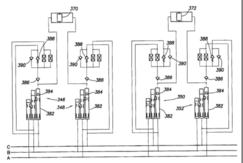
Referring additionally now to FIGS. 8A-C, a well control system
hydraulic schematic embodying principles of the present invention is
representatively illustrated. This hydraulic schematic utilizes
actuation control devices 346, 348, 350, 352, 354, 356, 358, 360,
CA 02398715 2002-07-29
WO 01/63089 PCT/US00/10116
_29_
3 6 2, 3 64, 3 6 6, 3 6 8 to control displacement of pistons in actuators 3 7
0 ,
372, 374, 376, 378, 380, respectively. The actuators 370, 372, 374,
376, 378, 380 are shown apart from ~ their respective well tool
assemblies.
Each of the control devices 346, 348, 350, 352, 354, 356, 358,
3 6 0, 3 6 2, 3 6 4, 3 6 6, 3 6 8 includes a sequence detector 3 8 2, similar
to
the sequence detector 302 described above, and indicated schematically
in FIGS. 8A-C as a series of three pistons. One of the pistons of each
sequence detector 382 has a prong 384 which is used to unseat a check
valve 386, in a manner similar to that in which the check valve 314 is
unseated by the prong 322 described above. A relief valve 388, similar
to the relief valve 316 described above, is connected to the respective
check valve 386 of each control device 346, 348, 350, 352, 354, 356,
358, 360, 362, 364, 366, 368. In addition, each control device 346,
348, 350, 352, 354, 356, 358, 360, 362, 364, 366, 368 includes
another check valve 390 interconnected across the relief valve 388, so
that flow through the check valve is permitted in the same direction as
flow is permitted through the check valve 386 prior to any of the
control devices being selected. The purpose for the check valves 390
will be appreciated from the further description of the hydraulic
schematic set forth below.
Considering the control device 346 initially, it may be seen from
FIG. 8A that the correct sequence code for selecting the control device is
01"1', that is, pressure is not to be applied to hydraulic line A, pressure
is to be applied to hydraulic line B second, and pressure is to be applied to
hydraulic line C first. The pressures applied to hydraulic lines B and C
should be sufficiently great to displace the corresponding pistons of the
sequence detector 382, and accordingly displace the prong 384 to
unseat the check valve 3 8 6.
Note that hydraulic line B is connected to the relief valve 388.
Thus, if pressure on hydraulic line B is sufficient to open the relief valve
CA 02398715 2002-07-29
WO 01/63089 PCT/US00/10116
-30-
388, then when the check valve 386 is opened by the prong 384,
hydraulic line B will be placed in fluid communication with the
actuator 370 and will bias the piston thereof to the right as viewed in
FIG. 8A.
Fluid in the actuator 370 to the right of its piston will be displaced
out of the actuator, through the check valves 386, 390 of the control
device 348 and to hydraulic line A. Recall that hydraulic line A should
not have pressure applied thereto when the control device 346 is
selected. Thus, the actuator 370 piston may be displaced to the right b y
merely applying a first predetermined pressure to hydraulic line C,
then to hydraulic line B, and if the first predetermined pressure is not
sufficiently great to open the relief valve 388 of the control device 346,
increasing the pressure on hydraulic line B to a second predetermined
pressure.
Preferably, the first predetermined pressure for each of the
control devices 346, 348, 350, 352, 354, 356, 358, 360, 362, 364,
366, 368 is less than that needed to open its associated relief valve 388,
so that the pressures on the hydraulic lines A, B, C may be permitted to
stabilize prior to operating any of the actuators 370, 372, 374, 376,
378, 380. In this manner, a false sequence code generated due to
fluctuations in the pressures on the hydraulic lines, delays in receiving
the pressures at the control devices 346, 348, 350, 352, 354, 356, 358,
360, 362, 364, 366, 368, etc. will not cause any of the actuators 370,
372, 374, 376, 378, 380 to be operated.
To displace the actuator 370 piston to the left as viewed in FIG.
8A, the control device 348 is selected by generating sequence code 1"01'
on the hydraulic lines A, B, C, that is, pressure is first applied to
hydraulic line C, then to hydraulic line A, and not to hydraulic line B.
Upon receipt of the appropriate sequence code, the prong 384 opens the
3 0 check valve 3 8 6. An increased pressure is then applied to hydraulic
CA 02398715 2002-07-29
WO 01/63089 PCT/US00/10116
_31_
line A, which pressure is transmitted through the relief valve 388 and
open check valve 386 to the right side of the actuator 370 piston.
When the actuator 370 piston displaces to the left, fluid on the left
side of the piston is displaced through the check valves 386, 390 of the
control device 346 to hydraulic line B. Recall that hydraulic line B
should not have pressure applied thereto when the control device 348 is
selected. Thus, the actuator 370 piston may be displaced to the left by
merely applying a first predetermined pressure to hydraulic line C,
then to hydraulic line A, and if the first predetermined pressure is not
sufficiently great to open the relief valve 388 of the control device 348,
increasing the pressure on hydraulic line A to a second predetermined
pressure.
Selection of the remaining control devices 350, 352, 354, 356,
358, 360, 362, 364, 366, 368 will not be described further herein,
since such selections are similar to the manner in which the control
devices 346, 348 are selected as described above. However, the
following table lists the sequence codes used in the well control system of
FIGS. 8A-C, and the corresponding mode of operation of the selected
actuator:
2 0 Sequence Code Actuation
A B C
0 1"p 1' Displace Actuator 370 Piston to the Right
1"p 0 1' Displace Actuator 3 70 Piston to the Left
0 1'p 1 " Displace Actuator 3 72 Piston to the Right
1'p 0 1 " Displace Actuator 3 72 Piston to the Left
0 1' 1"p Displace Actuator 3 74 Piston to the Right
1'p 1" 0 Displace Actuator 3 74 Piston to the Left
0 1" 1'p Displace Actuator 3 76 Piston to the Right
1"p 1' 0 Displace Actuator 3 76 Piston to the Left
CA 02398715 2002-07-29
WO 01/63089 PCT/US00/10116
-32-
1' 0 1"p Displace Actuator 378 Piston to the Right
1" 1'p 0 Displace Actuator 378 Piston to the Left
1" 0 1'p Displace Actuator 380 Piston to the Right
1' I"p 0 Displace Actuator 380 Piston to the Left
In the above table, the "p" in each sequence code indicates the
hydraulic line to which an increased pressure is applied to open the
relief valve 388 of the selected control device 346, 348, 350, 352, 354,
356, 358, 360, 362, 364, 366, 368. Note that, other than the "p"
designation, the sequence codes for the control devices 346, 358 are the
same. Thus, both of the control devices 346, 358 are selected when the
sequence code 0 1" 1' is generated on the hydraulic. lines A, B, C, but
neither of the actuator 370, 376 pistons is displaced until the increased
pressure is applied to open the relief valve 388 of one of the selected
control devices.
In the same manner, each of the other sequence codes is used
twice, with the increased pressure applied a different hydraulic line
being used to distinguish between the two. If, however, an increased
pressure were not used to cause operation of an actuator after selection
of a control device, the number of available sequence codes would be
halved.
Note that more than the three hydraulic lines A, B, C may be
used in the well control system of FIGS. 8A-C. For example, a fourth
hydraulic line D could be used, and it could be interconnected in place of
one of the hydraulic lines A, B, C for additional control devices, thereby
providing still further possible sequence codes.
Referring additionally now to FIGS. 9A&B, another actuation
control device 394 embodying principles of the present invention is
representatively illustrated. The control device 394 is shown
schematically interconnected to an actuator 396 apart from a well tool
CA 02398715 2002-07-29
WO 01/63089 PCT/US00/10116
-33-
assembly, it being understood that the actuator may be used in any well
tool assembly, such as a valve assembly, etc.
The control device 394 is similar in some respects to the control
device 300 described above, in that an appropriate sequence of pressure
applied successively to ports 398, 400, 402 thereof is used to select the
control device 394 for operation of the actuator 396. However, the
control device 394 differs substantially from the control device 300 in
at least one respect in that the ports 398, 400 used to select the control
device are also used to supply pressure to output ports 404, 405 when
l0 the control device is selected.
Pressure at input port 398 biases an inner piston 406 to the right
as viewed in FIG. 9A, against a biasing force exerted by an inner spring
408. Pressure at input port 400 biases an outer annular piston 410 to
the right against a biasing force exerted by an outer spring 412. An
elongated prong 414 extends to the right from the inner piston 406 and
is representatively formed as a part of the inner piston.
When the inner piston 406 displaces to the right, the prong 414
engages and unseats a check valve 416 . The check valve 41 & prevents
fluid flow from the input port 400 to the output port 404, until the
check valve is unseated. A closure member 418 of the check valve 416
has an elongated prong 420 formed thereon and extending to the right.
When the check valve 416 is unseated, the prong 420 displaces to the
right, and engages and unseats another check valve 422. The check
valve 4 2 2 prevents fluid flow from the input port 3 9 8 to the output port
405, until the check valve is unseated.
Note that the closure member 418 of the check valve 416 is
displaced a substantial distance (approximately .150 - .200 in.) from a
seat 424 of the check valve when the prong 414 unseats it. This is a
substantial advantage of the control device 394, since it significantly
3 0 reduces the possibility of the check valve 416 becoming contaminated
with debris lodged between its seat 424 and closure member 418. A
CA 02398715 2002-07-29
WO 01/63089 PCT/US00/10116
-34-
closure member 426 of the check valve 422 is also displaced a
substantial distance (approximately .100 - .150 in.) from a seat 428 of
the check valve when the prong 420 unseats it. Thus, the check valve
422 is also resistant to debris contamination between its seat 428 and
closure member 4 2 6 .
The inner piston 406 will only displace to the right in response to
pressure being applied to the input port 398 prior to the pressure being
applied to the input port 400. This is due to the fact that a series of balls
430 is received in a radially reduced portion 432 of the inner piston
406 through openings in a sleeve 434 positioned radially between the
inner and outer pistons 406, 410. The outer piston 410 maintains the
balls 430 engaged in the radially reduced portion 432 as depicted in
FIG. 9A.
To permit rightward displacement of the inner piston 406, an
internal groove 436 formed in the outer piston 410 must be aligned
with the balls 430, so that the balls may be received in the groove,
releasing the inner piston. The balls 430, sleeve 434 and outer piston
410 thus make up a latch for selectively permitting and preventing
displacement of the inner piston 406. This is similar in some respects to
the manner in which the piston 326 and ball 383 form a latching
device for selectively permitting and preventing displacement of the
piston 318 in the control device 300 described above.
If, however; the outer piston 410 is displaced to the right b y
pressure applied to the input port 400 prior to pressure being applied to
the input port 398, the outer piston 410 will "over travel", that is, the
groove 436 will displace to the right of the balls 430, and the outer
piston will continue to prevent the balls from disengaging from the
inner piston 406. Thus, pressure must be applied first to the input port
398, and then to the input port 400, so that when the outer piston 410
displaces to the right, the inner piston 406 will force the balls 430
outward into the groove 4 3 6 .
CA 02398715 2002-07-29
WO 01/63089 PCT/US00/10116
-35-
The remaining input port 402 is in fluid communication with the
right hand ends of the pistons 406, 410 as depicted in FIG. 9A.
Therefore, if the pressure is applied to the input port 402, both of the
pistons 406, 410 are prevented from displacing to the right. The
combination of the pressure at the input port 402 and the associated
leftward biasing force of the respective springs 408, 4r2 will prevent
any rightward displacement of the pistons 406, 410. Thus, the pressure
must not be applied to the input port 402 when the control device 394 is
selected.
Another distinctive feature of the control device 394 is a balance
valve 43 8 associated with the inner piston 40 6. The balance valve 4 3 8
includes a tapered outer portion 440 formed on the inner piston 406
and a similarly tapered seat 442. When the inner piston 406 is in its
leftward position as shown in FIG. 9A, the balance valve 438 is open,
permitting fluid communication between the output ports 404, 405,
and thereby maintaining the actuator 396 in a pressure balanced
condition. When the inner piston 406 displaces rightward, however,
the balance valve 438 is closed, preventing fluid communication
between the output ports 404, 405, and enabling a pressure differential
2 0 to be created between the output ports to displace the actuator 3 9 6
piston.
Therefore, to operate the actuator 396, pressure sufficient to
overcome the biasing force of the spring 408 is first applied to the input
port 398, and then pressure sufficient to overcome the biasing force of
the outer spring 412 is applied to the input port 400. Pressure is not
applied to the input port 402.
The pressure applied to the input port 398 biases the inner piston
406 to the right. The pressure applied to the input port 400 displaces
the outer piston 410 to the right. When the groove 436 is aligned with
the balls 430, they are forced outward and the inner piston 406
displaces to the right.
CA 02398715 2002-07-29
WO 01/63089 PCT/US00/10116
-36-
Rightward displacement of the inner piston 406 opens the check
valves 416, 422 and closes the balance valve 438. At this point, the
input port 398 is placed in fluid communication with the output port
405, and the input port 400 is placed in fluid communication with the
output port 404, and fluid communication between the output ports is
prevented by the closed balance valve 438. Pressure may now be
increased on the input port 3 9 8 to displace the actuator 3 9 6 piston to
the right, or pressure may be increased on the input port 400 to displace
the actuator piston to the left.
Fluid displaced from the actuator 396 when its piston displaces to
the right is received in the output port 404 and transmitted through
the control device 394 to the input port 400. Fluid displaced from the
actuator 396 when its piston displaces to the left is received in the
output port 405 and transmitted through the control device 394 to the
input port 398. Thus, the fluid transmitted to and from the actuator
396 when it is operated "U-tubes" between the input ports 398, 400.
The fluid received from the actuator 396 is not transmitted to the input
port 402 to which no pressure was applied, unlike the manner in which
the fluid received from the actuator 370 is transmitted to the
unpressurized port in the control device 346 of the well control system
of FIGS. 8A-C described above.
The control device 394 may be interconnected to three hydraulic
lines A, B, C at the input ports 398, 400, 402, similar to the manner in
which the control devices 346, 348, 350, 352, 354, 356, 358, 360,
362, 364, 366, 368 are connected to the hydraulic lines in the well
control system of FIGS. 8A-C. That is, the hydraulic lines A, B, C may
be connected to the input ports 398, 400, 402 to produce different
sequence codes. For example, if input port 398 is connected to hydraulic
line A, input port 400 is connected to hydraulic line B, and input port
402 is connected to hydraulic line C, the resulting sequence code would
be 1'1"0. If input port 398 is connected to hydraulic line C, input port
CA 02398715 2002-07-29
WO 01/63089 PCT/US00/10116
-3 7-
400 is connected to hydraulic line B, and input port 402 is connected to
hydraulic line A, the resulting sequence code would be 01" 1'.
Another substantial difference between the control device 3 9 4
and the control devices 346, 348, 350, 352, 354, 356, 358, 360, 3 62,
3 6 4, 3 6 6, 3 6 8 of the well control system of FIGS. 8A-C is that only one
of the control device 394 is needed to select an actuator 396 for
operation thereof. Thus, only half the number of sequence codes are
needed to control operation of the same number of actuators.
Of course, a person skilled in the art would, upon a c areful
consideration of the above description of representative embodiments of
the invention, readily appreciate that many modifications, additions,
substitutions, deletions, and other changes may be made to these
specific embodiments, and such changes are contemplated by the
principles of the present invention. For example, the above examples of
embodiments of the present invention have utilized only one
predetermined pressure level in selecting one or more control devices for
actuation of a corresponding well tool, but it will be readily appreciated
that multiple predetermined pressure levels may be used to select a
control device, such as by using pilot operated valves which operate in
response to different fluid pressures on their pilot inputs. Accordingly,
the foregoing detailed description is to be clearly understood as being
given by way of illustration and example only, the spirit and scope of
the present invention being lirizited solely by the appended claims.