Language selection

Search

Patent 2398830 Summary

Third-party information liability

Some of the information on this Web page has been provided by external sources. The Government of Canada is not responsible for the accuracy, reliability or currency of the information supplied by external sources. Users wishing to rely upon this information should consult directly with the source of the information. Content provided by external sources is not subject to official languages, privacy and accessibility requirements.

Claims and Abstract availability

Any discrepancies in the text and image of the Claims and Abstract are due to differing posting times. Text of the Claims and Abstract are posted:

  • At the time the application is open to public inspection;
  • At the time of issue of the patent (grant).
(12) Patent: (11) CA 2398830
(54) English Title: CARGO RESTRAINT DEVICE
(54) French Title: DISPOSITIF DE RETENUE DE CHARGE
Status: Term Expired - Post Grant Beyond Limit
Bibliographic Data
(51) International Patent Classification (IPC):
  • B60P 07/08 (2006.01)
  • B60N 02/28 (2006.01)
(72) Inventors :
  • AUSTIN, DONALD M. (Canada)
(73) Owners :
  • M & C CORPORATION
(71) Applicants :
  • M & C CORPORATION (United States of America)
(74) Agent: MACRAE & CO.
(74) Associate agent:
(45) Issued: 2008-01-15
(86) PCT Filing Date: 2001-02-21
(87) Open to Public Inspection: 2001-08-30
Examination requested: 2005-11-22
Availability of licence: N/A
Dedicated to the Public: N/A
(25) Language of filing: English

Patent Cooperation Treaty (PCT): Yes
(86) PCT Filing Number: PCT/US2001/005631
(87) International Publication Number: US2001005631
(85) National Entry: 2002-07-29

(30) Application Priority Data:
Application No. Country/Territory Date
09/510,584 (United States of America) 2000-02-22

Abstracts

English Abstract


A cargo restraint has a D-ring
(18) with cold-headed opposed end portions (26,
28) spaced slightly apart and trapped in a gap
in a passageway (40) of an anchor bracket and
tensioned against edges of the gap to prevent
rattling and withdrawal of the ends of the D-ring
(18) out of the bracket.


French Abstract

Une retenue de charge a un anneau en forme de D (18) doté de portions d'extrémités opposées (26, 28) frappées à froid, légèrement séparées, coincées dans un trou d'une voie de passage (40) d'un point d'ancrage et tendues contre les bords du trou afin d'éviter le bruit et le retrait des extrémités de l'anneau en D (18) hors dudit point.

Claims

Note: Claims are shown in the official language in which they were submitted.

WHAT IS CLAIMED IS:
1. A cargo restraint for attachment to a member to which a cargo
is to be tethered comprising, in combination:
an anchor bracket adapted to overlie a surface of the member to which
the cargo restraint is to be attached;
a fastener projecting through the anchor bracket for attaching the same
to said member;
said bracket formed to provide a generally cylindrical passageway
interrupted by a gap defined by axially spaced apart edges of the bracket
surrounding
the passageway;
a stiffly resilient cargo ring having a pair of opposed linearly
extending end portions for reception in said cylindrical passageway and
terminating
in opposed spaced apart cold-headed ends; and
said cold-headed ends disposed in said gap to prevent withdrawal of
the ring from the passageway, and tensioned linearly apart and against the
axially
spaced apart edges of the bracket to prevent rattling when the restraint is
not
subjected to a cargo loading.
2. The invention defined by claim 1 in which the end portions of
the D-ring is formed of cylindrical rod material.
3. The invention defined by claim 1 wherein the bracket is
formed with a lower leaf having opposed upwardly extending marginal flanges
and
an upper leaf is nested on the lower leaf between such flanges with said
fastener
projecting through the leaves and having a reinforcing flange overlying the
upper leaf
to prevent separation of the leaves when the D-ring is subjected to cargo
loading.
4. The invention defined by claim 1 wherein said bracket is
formed of a single piece of sheet metal rolled around said pair of opposed
linearly
extending end portions to form said cylindrical passageway with the cold-
headed
ends locked in the passageway by said gap.
-6-

Description

Note: Descriptions are shown in the official language in which they were submitted.


CA 02398830 2002-07-29
WO 01/62546 PCT/US01/05631
CARGO RESTRAINT DEVICE
Field of Invention
This invention relates to cargo restraint devices for providing
anchorage for cargo or a child seat in an automotive vehicle.
Background of the Invention
Various designs of cargo restraints or the like are shown in the
following United States letters patent: 283,320; 607,543; 2,701,114;
3,002,723;
3,033,600; 5,248,176; and British 1,433,279. This art suggests that it is old
to
utilize a D-ring or the like with an anchor bracket which can swivel around a
fastener
projecting through the bracket for attaching it to a member upon which the
cargo
restraint is to be mounted. In British Patent 1,433,279, a ring for receiving
a seat
belt strap has coaxially aligned ends received in a cylindrical passageway at
one edge
of the bracket with ends of the ring projecting laterally slightly into an
opening
formed in a wall of the bracket.
Problems with prior art restraint devices of the character shown in the
aforementioned patents and in other restraint devices which have been on the
market
is that such devices are not capable of withstanding the shock loadings
occurring
when automotive vehicles are involved in crashes. The ends of the D-ring have
pulled out of the anchor brackets. To overcome this deficiency, it has been
suggested that the ends of the D-ring be welded together. Such welding
increases
the cost of the restraint device and requires a secondary manufacturing
operation.
Summary of the Invention
My cargo restraint device which is useful in anchoring cargo or a child
seat in an automotive vehicle allows the D-ring to pivot in the anchor bracket
with
a slight friction which is sufficient to prevent rattling, binding or problems
of
alignment of the D-ring in the anchor bracket. Importantly, the ends of the D-
ring
-1-

CA 02398830 2002-07-29
WO 01/62546 PCT/US01/05631
are cold-headed and spaced slightly apart such that upon assembling the D-ring
to the
bracket, the cold-headed ends of the D-ring may be squeezed slightly together
and
after the ends are enclosed by the bracket, the ends are released and will
then bear
against opposed surfaces of the bracket not only to prevent withdrawal of the
ends
from the anchor bracket but also provide the anti-rattling feature heretofore
mentioned.
Brief Description of the Drawings
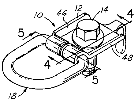
Figure 1 is a perspective view of my improved cargo restraint device;
Figure 2 is a top plan view of the cargo restraint device;
Figure 3 is a side elevation of my improved cargo restraint device;
Figure 4 is a cross-sectional view taken on the line 4-4 of Figure 1;
Figure 5 is a cross-sectional view taken on the line 5-5 of Figure 1;
and
Figure 6 is a plan view of a D-ring usable in my cargo restraint
device.
Brief Description of the Preferred Embodiment
Referring now to the drawings, the cargo restraint 10 comprises an
anchor bracket 12, a fastener 14 projecting through the anchor bracket for
attaching
the same to a member 16 to which the cargo (not shown) is to be tethered by D-
ring
18. The anchor bracket 12 is formed of sheet metal folded upon itself and
around
the D-ring to entrap the D-ring in the bracket such that the ring may be swung
vertically on the bracket to position it in line with the cargo loading.
-2-

CA 02398830 2002-07-29
WO 01/62546 PCT/US01/05631
The D-ring 18 is formed of stiffly resilient steel rod having a closed
loop configuration with a bight portion 20 of generally U-shaped configuration
terminating in axially aligned opposed linearly extending end portions 22 and
24,
themselves terminating in cold-headed ends 26 and 28, spaced apart axially to
provide a gap 30 therebetween of approximately .2mm. Such gap enables the ends
22 and 24 to be squeezed toward each other when the anchor bracket 12 is
wrapped
about end portions 22 and 24 as hereinafter described. End portions 22 and 24
of
the D-ring 18 are of cylindrical configuration with cold-headed ends 26 and 28
projecting radially beyond the diameter of the end portions 22 and 24 as best
shown
in Figs. 5 and 6.
The anchor bracket 12 is formed of sheet steel or other suitably strong
material and has upper and lower leaves 32 and 34 respectively of generally
square
configuration iri plan view as shown in Figs. 1 and 2. The lower leaf has a
tail
portion 36 terminating in a depending projection 38 for reception in an
aperture (not
shown) in the member 16 to lock the anchor bracket in a predetermined rotated
position. At the opposite edge of the anchor bracket from the tail portion 36,
the
bracket is shaped or formed to provide a generally cylindrical passageway 40
interrupted by a gap perpendicular to the axis of the cylindrical passageway
and
defined by axially spaced apart edges 42 and 44 of the bracket material
forming the
cylindrical passageway 40 and best shown in Figs. 2 and 5. The leaves 32 and
34
of the anchor bracket are formed around the end portions 22 and 24 of the D-
ring to
provide the passageway 40 and at the time of such formation the D-ring is
squeezed
urging the end portions 22 and 24 into abutting relation. The gap in the
cylindrical
passageway 40 has the opposed surfaces 42 and 44 spaced apart a distance
slightly
less than the distance between the backsides of the cold-headed ends 26 and
28, such
that after the anchor bracket has been formed around such end portions to trap
the
cold-headed ends 26 and 28, the squeezing action on end portions 22 and 24 may
be
released to permit cold-headed ends to spring back and engage the edges 42 and
44
of the bracket. The lower leaf 34 of the bracket along the edges extending
from the
tail 34 to the cylindrical passage 40 are shaped to provide angularly upwardly
extending reinforcing flanges 46 and 48 to stiffen the leaf, and the upper
leaf 32
nests between such upwardly turned flanges as best shown in Figs. 1 and 2. An
-3-

CA 02398830 2002-07-29
WO 01/62546 PCT/US01/05631
aperture through the leaves allows for the passage of the fastener 14 with a
flange 50
of the fastener overlying the upper leaf 32 as best shown in Figs. 1, 2 and 4.
Before formation of the bracket around the end portions 22 and 24 as
above described, the leaves 32 and 34 are slotted to provide the gap defined
by the
edges 42 and 44, and then the D-ring is laid on the leaves and the leaves are
formed
around the end portions 22 and 24 into the configuration best shown in Fig. 4.
With the cold-headed ends 26 and 28 disposed in the transverse slot
or gap in the cylindrical passageway 40 and with the cold-headed ends 26 and
28,
tension slightly against the edges 42 and 44, the D-ring will not rattle in
the bracket
and will tend to remain in a rotated position in which it is placed relative
to the
bracket. As a result of this construction, the pair of opposed linearly extend
end
portions 22 and 24 having the cold-headed ends 26 and 28, cannot be withdrawn
from the bracket. The fastener 14 prevents the leaves from opening up and the
cold-
headed ends 26 and 28 prevent the end portions 22 and 24 from being pulled out
of
the passageway. Also, this construction avoids the necessity of welding the
ends of
the end portions 22 and 24 together, thus reducing the cost of manufacture,
and the
tensioning of the cold-headed ends against the confronting edges of the
bracket
eliminates undesirable rattling.
Thus, I have provided a cargo restraint useful as a child seat tether
which will withstand the loads specified for such tethers. Heretofore, the
ends of D-
rings which were not welded together or to the anchor brackets were too weak
to
withstand the tether loads. In the absence of a construction of the character
I have
disclosed herein, I found it necessary to weld the ends of the D-ring in order
to
prevent their withdrawal from the bracket. My construction and design avoids
this
requirement.
While embodiments of the invention have been illustrated and
described, it is not intended that these embodiments illustrate and describe
all
possible forms of the invention. Rather, the words used in the specification
are
-4-

CA 02398830 2002-07-29
WO 01/62546 PCT/US01/05631
words of description rather than limitation, and it is understood that various
changes
may be made without departing from the spirit and scope of the invention.
-5-

Representative Drawing
A single figure which represents the drawing illustrating the invention.
Administrative Status

2024-08-01:As part of the Next Generation Patents (NGP) transition, the Canadian Patents Database (CPD) now contains a more detailed Event History, which replicates the Event Log of our new back-office solution.

Please note that "Inactive:" events refers to events no longer in use in our new back-office solution.

For a clearer understanding of the status of the application/patent presented on this page, the site Disclaimer , as well as the definitions for Patent , Event History , Maintenance Fee  and Payment History  should be consulted.

Event History

Description Date
Inactive: Expired (new Act pat) 2021-02-22
Common Representative Appointed 2019-10-30
Inactive: Late MF processed 2010-03-03
Letter Sent 2010-02-22
Grant by Issuance 2008-01-15
Inactive: Cover page published 2008-01-14
Pre-grant 2007-10-30
Inactive: Final fee received 2007-10-30
Notice of Allowance is Issued 2007-09-10
Letter Sent 2007-09-10
Notice of Allowance is Issued 2007-09-10
Inactive: Approved for allowance (AFA) 2007-07-31
Inactive: IPC from MCD 2006-03-12
Letter Sent 2005-12-01
Request for Examination Requirements Determined Compliant 2005-11-22
All Requirements for Examination Determined Compliant 2005-11-22
Request for Examination Received 2005-11-22
Letter Sent 2003-02-28
Inactive: Single transfer 2003-01-03
Inactive: Courtesy letter - Evidence 2002-12-17
Inactive: Cover page published 2002-12-11
Inactive: Notice - National entry - No RFE 2002-12-09
Application Received - PCT 2002-09-27
National Entry Requirements Determined Compliant 2002-07-29
Application Published (Open to Public Inspection) 2001-08-30

Abandonment History

There is no abandonment history.

Maintenance Fee

The last payment was received on 2007-01-11

Note : If the full payment has not been received on or before the date indicated, a further fee may be required which may be one of the following

  • the reinstatement fee;
  • the late payment fee; or
  • additional fee to reverse deemed expiry.

Patent fees are adjusted on the 1st of January every year. The amounts above are the current amounts if received by December 31 of the current year.
Please refer to the CIPO Patent Fees web page to see all current fee amounts.

Owners on Record

Note: Records showing the ownership history in alphabetical order.

Current Owners on Record
M & C CORPORATION
Past Owners on Record
DONALD M. AUSTIN
Past Owners that do not appear in the "Owners on Record" listing will appear in other documentation within the application.
Documents

To view selected files, please enter reCAPTCHA code :


To view images, click a link in the Document Description column. To download the documents, select one or more checkboxes in the first column and then click the "Download Selected in PDF format (Zip Archive)" or the "Download Selected as Single PDF" button.

List of published and non-published patent-specific documents on the CPD .

If you have any difficulty accessing content, you can call the Client Service Centre at 1-866-997-1936 or send them an e-mail at CIPO Client Service Centre.


Document
Description 
Date
(yyyy-mm-dd) 
Number of pages   Size of Image (KB) 
Representative drawing 2002-07-28 1 7
Abstract 2002-07-28 1 49
Claims 2002-07-28 1 45
Drawings 2002-07-28 1 30
Description 2002-07-28 5 201
Representative drawing 2007-12-13 1 14
Reminder of maintenance fee due 2002-12-08 1 106
Notice of National Entry 2002-12-08 1 189
Courtesy - Certificate of registration (related document(s)) 2003-02-27 1 130
Reminder - Request for Examination 2005-10-23 1 115
Acknowledgement of Request for Examination 2005-11-30 1 176
Commissioner's Notice - Application Found Allowable 2007-09-09 1 164
Maintenance Fee Notice 2010-03-22 1 171
Late Payment Acknowledgement 2010-03-22 1 164
PCT 2002-07-28 5 226
Correspondence 2002-12-08 1 23
Correspondence 2007-10-29 1 32
Fees 2011-02-20 1 201