Sélection de la langue

Search

Sommaire du brevet 2398830 

Énoncé de désistement de responsabilité concernant l'information provenant de tiers

Une partie des informations de ce site Web a été fournie par des sources externes. Le gouvernement du Canada n'assume aucune responsabilité concernant la précision, l'actualité ou la fiabilité des informations fournies par les sources externes. Les utilisateurs qui désirent employer cette information devraient consulter directement la source des informations. Le contenu fourni par les sources externes n'est pas assujetti aux exigences sur les langues officielles, la protection des renseignements personnels et l'accessibilité.

Disponibilité de l'Abrégé et des Revendications

L'apparition de différences dans le texte et l'image des Revendications et de l'Abrégé dépend du moment auquel le document est publié. Les textes des Revendications et de l'Abrégé sont affichés :

  • lorsque la demande peut être examinée par le public;
  • lorsque le brevet est émis (délivrance).
(12) Brevet: (11) CA 2398830
(54) Titre français: DISPOSITIF DE RETENUE DE CHARGE
(54) Titre anglais: CARGO RESTRAINT DEVICE
Statut: Durée expirée - au-delà du délai suivant l'octroi
Données bibliographiques
(51) Classification internationale des brevets (CIB):
  • B60P 07/08 (2006.01)
  • B60N 02/28 (2006.01)
(72) Inventeurs :
  • AUSTIN, DONALD M. (Canada)
(73) Titulaires :
  • M & C CORPORATION
(71) Demandeurs :
  • M & C CORPORATION (Etats-Unis d'Amérique)
(74) Agent: MACRAE & CO.
(74) Co-agent:
(45) Délivré: 2008-01-15
(86) Date de dépôt PCT: 2001-02-21
(87) Mise à la disponibilité du public: 2001-08-30
Requête d'examen: 2005-11-22
Licence disponible: S.O.
Cédé au domaine public: S.O.
(25) Langue des documents déposés: Anglais

Traité de coopération en matière de brevets (PCT): Oui
(86) Numéro de la demande PCT: PCT/US2001/005631
(87) Numéro de publication internationale PCT: US2001005631
(85) Entrée nationale: 2002-07-29

(30) Données de priorité de la demande:
Numéro de la demande Pays / territoire Date
09/510,584 (Etats-Unis d'Amérique) 2000-02-22

Abrégés

Abrégé français

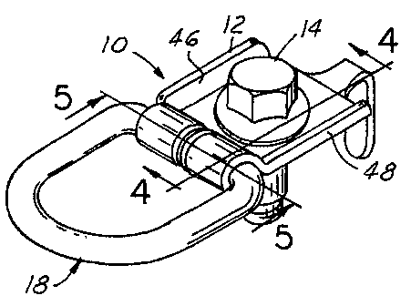
Une retenue de charge a un anneau en forme de D (18) doté de portions d'extrémités opposées (26, 28) frappées à froid, légèrement séparées, coincées dans un trou d'une voie de passage (40) d'un point d'ancrage et tendues contre les bords du trou afin d'éviter le bruit et le retrait des extrémités de l'anneau en D (18) hors dudit point.


Abrégé anglais


A cargo restraint has a D-ring
(18) with cold-headed opposed end portions (26,
28) spaced slightly apart and trapped in a gap
in a passageway (40) of an anchor bracket and
tensioned against edges of the gap to prevent
rattling and withdrawal of the ends of the D-ring
(18) out of the bracket.

Revendications

Note : Les revendications sont présentées dans la langue officielle dans laquelle elles ont été soumises.


WHAT IS CLAIMED IS:
1. A cargo restraint for attachment to a member to which a cargo
is to be tethered comprising, in combination:
an anchor bracket adapted to overlie a surface of the member to which
the cargo restraint is to be attached;
a fastener projecting through the anchor bracket for attaching the same
to said member;
said bracket formed to provide a generally cylindrical passageway
interrupted by a gap defined by axially spaced apart edges of the bracket
surrounding
the passageway;
a stiffly resilient cargo ring having a pair of opposed linearly
extending end portions for reception in said cylindrical passageway and
terminating
in opposed spaced apart cold-headed ends; and
said cold-headed ends disposed in said gap to prevent withdrawal of
the ring from the passageway, and tensioned linearly apart and against the
axially
spaced apart edges of the bracket to prevent rattling when the restraint is
not
subjected to a cargo loading.
2. The invention defined by claim 1 in which the end portions of
the D-ring is formed of cylindrical rod material.
3. The invention defined by claim 1 wherein the bracket is
formed with a lower leaf having opposed upwardly extending marginal flanges
and
an upper leaf is nested on the lower leaf between such flanges with said
fastener
projecting through the leaves and having a reinforcing flange overlying the
upper leaf
to prevent separation of the leaves when the D-ring is subjected to cargo
loading.
4. The invention defined by claim 1 wherein said bracket is
formed of a single piece of sheet metal rolled around said pair of opposed
linearly
extending end portions to form said cylindrical passageway with the cold-
headed
ends locked in the passageway by said gap.
-6-

Description

Note : Les descriptions sont présentées dans la langue officielle dans laquelle elles ont été soumises.


CA 02398830 2002-07-29
WO 01/62546 PCT/US01/05631
CARGO RESTRAINT DEVICE
Field of Invention
This invention relates to cargo restraint devices for providing
anchorage for cargo or a child seat in an automotive vehicle.
Background of the Invention
Various designs of cargo restraints or the like are shown in the
following United States letters patent: 283,320; 607,543; 2,701,114;
3,002,723;
3,033,600; 5,248,176; and British 1,433,279. This art suggests that it is old
to
utilize a D-ring or the like with an anchor bracket which can swivel around a
fastener
projecting through the bracket for attaching it to a member upon which the
cargo
restraint is to be mounted. In British Patent 1,433,279, a ring for receiving
a seat
belt strap has coaxially aligned ends received in a cylindrical passageway at
one edge
of the bracket with ends of the ring projecting laterally slightly into an
opening
formed in a wall of the bracket.
Problems with prior art restraint devices of the character shown in the
aforementioned patents and in other restraint devices which have been on the
market
is that such devices are not capable of withstanding the shock loadings
occurring
when automotive vehicles are involved in crashes. The ends of the D-ring have
pulled out of the anchor brackets. To overcome this deficiency, it has been
suggested that the ends of the D-ring be welded together. Such welding
increases
the cost of the restraint device and requires a secondary manufacturing
operation.
Summary of the Invention
My cargo restraint device which is useful in anchoring cargo or a child
seat in an automotive vehicle allows the D-ring to pivot in the anchor bracket
with
a slight friction which is sufficient to prevent rattling, binding or problems
of
alignment of the D-ring in the anchor bracket. Importantly, the ends of the D-
ring
-1-

CA 02398830 2002-07-29
WO 01/62546 PCT/US01/05631
are cold-headed and spaced slightly apart such that upon assembling the D-ring
to the
bracket, the cold-headed ends of the D-ring may be squeezed slightly together
and
after the ends are enclosed by the bracket, the ends are released and will
then bear
against opposed surfaces of the bracket not only to prevent withdrawal of the
ends
from the anchor bracket but also provide the anti-rattling feature heretofore
mentioned.
Brief Description of the Drawings
Figure 1 is a perspective view of my improved cargo restraint device;
Figure 2 is a top plan view of the cargo restraint device;
Figure 3 is a side elevation of my improved cargo restraint device;
Figure 4 is a cross-sectional view taken on the line 4-4 of Figure 1;
Figure 5 is a cross-sectional view taken on the line 5-5 of Figure 1;
and
Figure 6 is a plan view of a D-ring usable in my cargo restraint
device.
Brief Description of the Preferred Embodiment
Referring now to the drawings, the cargo restraint 10 comprises an
anchor bracket 12, a fastener 14 projecting through the anchor bracket for
attaching
the same to a member 16 to which the cargo (not shown) is to be tethered by D-
ring
18. The anchor bracket 12 is formed of sheet metal folded upon itself and
around
the D-ring to entrap the D-ring in the bracket such that the ring may be swung
vertically on the bracket to position it in line with the cargo loading.
-2-

CA 02398830 2002-07-29
WO 01/62546 PCT/US01/05631
The D-ring 18 is formed of stiffly resilient steel rod having a closed
loop configuration with a bight portion 20 of generally U-shaped configuration
terminating in axially aligned opposed linearly extending end portions 22 and
24,
themselves terminating in cold-headed ends 26 and 28, spaced apart axially to
provide a gap 30 therebetween of approximately .2mm. Such gap enables the ends
22 and 24 to be squeezed toward each other when the anchor bracket 12 is
wrapped
about end portions 22 and 24 as hereinafter described. End portions 22 and 24
of
the D-ring 18 are of cylindrical configuration with cold-headed ends 26 and 28
projecting radially beyond the diameter of the end portions 22 and 24 as best
shown
in Figs. 5 and 6.
The anchor bracket 12 is formed of sheet steel or other suitably strong
material and has upper and lower leaves 32 and 34 respectively of generally
square
configuration iri plan view as shown in Figs. 1 and 2. The lower leaf has a
tail
portion 36 terminating in a depending projection 38 for reception in an
aperture (not
shown) in the member 16 to lock the anchor bracket in a predetermined rotated
position. At the opposite edge of the anchor bracket from the tail portion 36,
the
bracket is shaped or formed to provide a generally cylindrical passageway 40
interrupted by a gap perpendicular to the axis of the cylindrical passageway
and
defined by axially spaced apart edges 42 and 44 of the bracket material
forming the
cylindrical passageway 40 and best shown in Figs. 2 and 5. The leaves 32 and
34
of the anchor bracket are formed around the end portions 22 and 24 of the D-
ring to
provide the passageway 40 and at the time of such formation the D-ring is
squeezed
urging the end portions 22 and 24 into abutting relation. The gap in the
cylindrical
passageway 40 has the opposed surfaces 42 and 44 spaced apart a distance
slightly
less than the distance between the backsides of the cold-headed ends 26 and
28, such
that after the anchor bracket has been formed around such end portions to trap
the
cold-headed ends 26 and 28, the squeezing action on end portions 22 and 24 may
be
released to permit cold-headed ends to spring back and engage the edges 42 and
44
of the bracket. The lower leaf 34 of the bracket along the edges extending
from the
tail 34 to the cylindrical passage 40 are shaped to provide angularly upwardly
extending reinforcing flanges 46 and 48 to stiffen the leaf, and the upper
leaf 32
nests between such upwardly turned flanges as best shown in Figs. 1 and 2. An
-3-

CA 02398830 2002-07-29
WO 01/62546 PCT/US01/05631
aperture through the leaves allows for the passage of the fastener 14 with a
flange 50
of the fastener overlying the upper leaf 32 as best shown in Figs. 1, 2 and 4.
Before formation of the bracket around the end portions 22 and 24 as
above described, the leaves 32 and 34 are slotted to provide the gap defined
by the
edges 42 and 44, and then the D-ring is laid on the leaves and the leaves are
formed
around the end portions 22 and 24 into the configuration best shown in Fig. 4.
With the cold-headed ends 26 and 28 disposed in the transverse slot
or gap in the cylindrical passageway 40 and with the cold-headed ends 26 and
28,
tension slightly against the edges 42 and 44, the D-ring will not rattle in
the bracket
and will tend to remain in a rotated position in which it is placed relative
to the
bracket. As a result of this construction, the pair of opposed linearly extend
end
portions 22 and 24 having the cold-headed ends 26 and 28, cannot be withdrawn
from the bracket. The fastener 14 prevents the leaves from opening up and the
cold-
headed ends 26 and 28 prevent the end portions 22 and 24 from being pulled out
of
the passageway. Also, this construction avoids the necessity of welding the
ends of
the end portions 22 and 24 together, thus reducing the cost of manufacture,
and the
tensioning of the cold-headed ends against the confronting edges of the
bracket
eliminates undesirable rattling.
Thus, I have provided a cargo restraint useful as a child seat tether
which will withstand the loads specified for such tethers. Heretofore, the
ends of D-
rings which were not welded together or to the anchor brackets were too weak
to
withstand the tether loads. In the absence of a construction of the character
I have
disclosed herein, I found it necessary to weld the ends of the D-ring in order
to
prevent their withdrawal from the bracket. My construction and design avoids
this
requirement.
While embodiments of the invention have been illustrated and
described, it is not intended that these embodiments illustrate and describe
all
possible forms of the invention. Rather, the words used in the specification
are
-4-

CA 02398830 2002-07-29
WO 01/62546 PCT/US01/05631
words of description rather than limitation, and it is understood that various
changes
may be made without departing from the spirit and scope of the invention.
-5-

Dessin représentatif
Une figure unique qui représente un dessin illustrant l'invention.
États administratifs

2024-08-01 : Dans le cadre de la transition vers les Brevets de nouvelle génération (BNG), la base de données sur les brevets canadiens (BDBC) contient désormais un Historique d'événement plus détaillé, qui reproduit le Journal des événements de notre nouvelle solution interne.

Veuillez noter que les événements débutant par « Inactive : » se réfèrent à des événements qui ne sont plus utilisés dans notre nouvelle solution interne.

Pour une meilleure compréhension de l'état de la demande ou brevet qui figure sur cette page, la rubrique Mise en garde , et les descriptions de Brevet , Historique d'événement , Taxes périodiques et Historique des paiements devraient être consultées.

Historique d'événement

Description Date
Inactive : Périmé (brevet - nouvelle loi) 2021-02-22
Représentant commun nommé 2019-10-30
Inactive : TME en retard traitée 2010-03-03
Lettre envoyée 2010-02-22
Accordé par délivrance 2008-01-15
Inactive : Page couverture publiée 2008-01-14
Préoctroi 2007-10-30
Inactive : Taxe finale reçue 2007-10-30
Un avis d'acceptation est envoyé 2007-09-10
Lettre envoyée 2007-09-10
Un avis d'acceptation est envoyé 2007-09-10
Inactive : Approuvée aux fins d'acceptation (AFA) 2007-07-31
Inactive : CIB de MCD 2006-03-12
Lettre envoyée 2005-12-01
Exigences pour une requête d'examen - jugée conforme 2005-11-22
Toutes les exigences pour l'examen - jugée conforme 2005-11-22
Requête d'examen reçue 2005-11-22
Lettre envoyée 2003-02-28
Inactive : Transfert individuel 2003-01-03
Inactive : Lettre de courtoisie - Preuve 2002-12-17
Inactive : Page couverture publiée 2002-12-11
Inactive : Notice - Entrée phase nat. - Pas de RE 2002-12-09
Demande reçue - PCT 2002-09-27
Exigences pour l'entrée dans la phase nationale - jugée conforme 2002-07-29
Demande publiée (accessible au public) 2001-08-30

Historique d'abandonnement

Il n'y a pas d'historique d'abandonnement

Taxes périodiques

Le dernier paiement a été reçu le 2007-01-11

Avis : Si le paiement en totalité n'a pas été reçu au plus tard à la date indiquée, une taxe supplémentaire peut être imposée, soit une des taxes suivantes :

  • taxe de rétablissement ;
  • taxe pour paiement en souffrance ; ou
  • taxe additionnelle pour le renversement d'une péremption réputée.

Les taxes sur les brevets sont ajustées au 1er janvier de chaque année. Les montants ci-dessus sont les montants actuels s'ils sont reçus au plus tard le 31 décembre de l'année en cours.
Veuillez vous référer à la page web des taxes sur les brevets de l'OPIC pour voir tous les montants actuels des taxes.

Titulaires au dossier

Les titulaires actuels et antérieures au dossier sont affichés en ordre alphabétique.

Titulaires actuels au dossier
M & C CORPORATION
Titulaires antérieures au dossier
DONALD M. AUSTIN
Les propriétaires antérieurs qui ne figurent pas dans la liste des « Propriétaires au dossier » apparaîtront dans d'autres documents au dossier.
Documents

Pour visionner les fichiers sélectionnés, entrer le code reCAPTCHA :


Pour visualiser une image, cliquer sur un lien dans la colonne description du document. Pour télécharger l'image (les images), cliquer l'une ou plusieurs cases à cocher dans la première colonne et ensuite cliquer sur le bouton "Télécharger sélection en format PDF (archive Zip)" ou le bouton "Télécharger sélection (en un fichier PDF fusionné)".

Liste des documents de brevet publiés et non publiés sur la BDBC .

Si vous avez des difficultés à accéder au contenu, veuillez communiquer avec le Centre de services à la clientèle au 1-866-997-1936, ou envoyer un courriel au Centre de service à la clientèle de l'OPIC.


Description du
Document 
Date
(aaaa-mm-jj) 
Nombre de pages   Taille de l'image (Ko) 
Dessin représentatif 2002-07-28 1 7
Abrégé 2002-07-28 1 49
Revendications 2002-07-28 1 45
Dessins 2002-07-28 1 30
Description 2002-07-28 5 201
Dessin représentatif 2007-12-13 1 14
Rappel de taxe de maintien due 2002-12-08 1 106
Avis d'entree dans la phase nationale 2002-12-08 1 189
Courtoisie - Certificat d'enregistrement (document(s) connexe(s)) 2003-02-27 1 130
Rappel - requête d'examen 2005-10-23 1 115
Accusé de réception de la requête d'examen 2005-11-30 1 176
Avis du commissaire - Demande jugée acceptable 2007-09-09 1 164
Avis concernant la taxe de maintien 2010-03-22 1 171
Quittance d'un paiement en retard 2010-03-22 1 164
PCT 2002-07-28 5 226
Correspondance 2002-12-08 1 23
Correspondance 2007-10-29 1 32
Taxes 2011-02-20 1 201