Note: Descriptions are shown in the official language in which they were submitted.
CA 02398932 2002-08-20
-1-
TITLE OF THE INVENTION
RADIO COMMUNICATION SYSTEM, COMMUNICATION
TERMINAL, AND METHOD FOR TRANSMITTING BURST SIGNALS
BACKGROUND OF THE INVENTION
1. Field of the Invention
The present invention relates to a method
for transmitting burst signals in a radio
communication system, and more particularly to a
method and apparatus for appropriately dividing
and/or combining the burst signals to be transmitted,
and for transmitting the burst signals only during a
period when the radio transmission path condition is
fine, on the basis of the radio transmission path
condition between a transmitting station and a
receiving station, and of the transmission waiting
status of burst signals at the transmitting station.
2. Description of the Related Art
As a conventional method for transmitting
burst signals in the radio communication system,
International Publication W001/48952A1 discloses
controlling transmission availability of burst
signal.
This measures a time-averaged condition
and an instantaneous condition on the radio
transmission path between the transmitting station
and the receiving station, and controls the burst
signal transmission to be available only when the
instantaneous condition is better than the time-
averaged condition in order to reduce peak
transmission power or average transmission power and
thereby to reduce power consumption at the
transmitting station and interference to other
receiving stations.
However, the above conventional method
performs the burst signal transmission availability
control in units of a burst signal. Thus, it causes
CA 02398932 2002-08-20
-2-
a problem in that, in the case in which the
variation cycle between fine/not fine conditions of
the radio transmission path is shorter than the
burst signal length, the signal may be transmitted
under the circumstances that the transmission path
condition is not fine.
For example, in.the case of performing the
above conventional transmission availability control
using measured instantaneous value of path loss
variation as a parameter indicating the radio
transmission path condition, or in the case in which
the measured instantaneo-us value of path loss varies
quickly and a period for transmission allowed is
shorter than the burst signal length, only a period
where the measured instantaneous value of path loss
variation is large (i.e. where it is determined that
the transmission path condition is relatively
better) may be insufficient to complete the
transmission of burst signal. Then, the burst
signal has to be transmitted not only during the
period under better condition but also during a
period where the measured instantaneous value of
path loss variation is small (i.e. where it is
determined that the transmission path condition is
relatively worse), reducing advantages of the
transmission availability control.
Also, the above conventional burst signal
transmission availability control causes another
problem in that it keeps operating the processes
associated with this control even when the variation
cycle of the transmission path condition is very
short, and thereby the resultant advantages are
decreased.
Further, the above conventional burst
signal transmission availability control causes
another problem in that, in the case in which the
variation cycle of the transmission path condition
CA 02398932 2002-08-20
-3-
is very long, a transmission unavailable period is
caused to be long, and thereby the transmission
waiting time for the burst signals to be transmitted,
which are accumulated during such transmission
unavailable period, will be long, and large delay
will occur.
Thus, according to the conventional
transmission availability control, since the control
is performed in units of the burst signal, and is
always performed regardless of how long the
variation cycle of the transmission path condition
is, it may be possible that the advantages to be
obtained by the control cannot be sufficiently
obtained.
SUMMARY OF THE INVENTION
The present invention is directed to solve
these problems, and its object is to provide a
method, a system and an apparatus for transmitting
each burst signal with the transmission unit length
appropriate for the transmission path condition at
the time, with the burst signals
transmitting/receiving method for performing the
transmission availability control of the burst
signals on the basis of the radio transmission path
condition.
One aspect of the present invention is a
method for transmitting burst signals in a radio
communication system comprising a transmitting
station and a receiving station, the trarismitting
station comprising a measurement part for measuring
radio transmission path condition between the
transmitting station and the receiving station,
wherein the transmitting station adjusts the signal
length of the burst signal to be transmitted on the
basis of the measured result by the measurement part.
In this aspect, the above-described radio
CA 02398932 2007-08-22
27879-177
-4-
transmission path condition may be defined by one of
the following parameters or a combination thereof:
measured instantaneous value of path loss variation;
transmission error rate; transmission throughput;
distance between the transmitting station and the
receiving station; power of interference from other
stations; the number of other receiving stations
that intend to receive signals from an antenna of
the transmitting station; amount of information to
be transmitted; an average thereof; desired
transmission time; relative physical relationship
between the transmitting station and the receiving
station; and so on.
According to this aspect, the burst signal
can be transmitted with a desired signal length
after adjustment of its signal length on the basis
of the radio transmission path condition, rather
than being transmitted in units of the burst signal.
Alternatively, the burst signal
transmitting method according to the present
invention can select one desired transmission unit
length from a set of a plurality of predetermined
different unit lengths, and adjust the length of the
burst signal to be transmitted to the selected unit
length.
The burst signal transmitting method
according to the present invention can also adjust
the length of the .burst signal to be transmitted to
a fixed unit length.
CA 02398932 2007-08-22
27879-177
-4a-
According to another aspect of the present
invention, there is provided a radio communication system
comprising a transmitting station and a receiving station,
the transmitting station comprising a measurement part for
measuring radio transmission path condition between the
transmitting station and the receiving station, the
transmitting station further comprising: a transmission
availability determination part for determining transmission
availability of a burst signal on the basis of the measured
result by the measurement part; a signal length adjustment
part for adjusting the signal length of the burst signal to
be transmitted; and a transmission part for transmitting the
burst signal, whose signal length is adjusted by the signal
length adjustment part, to the receiving station on the
basis of the determination by the transmission availability
determination part, and for suspending the burst signal
transmission, even if the burst signal transmission has not
been completed, when it is determined that the burst signal
transmission is unavailable by the transmission availability
determination part.
According to still another aspect of the present
invention, there is provided a communication terminal
comprising a measurement part for measuring radio
transmission path condition between the communication
terminal and an opposing station communicating with it, the
communication terminal further comprising: a transmission
availability determination part for determining transmission
availability of a burst signal on the basis of the measured
result by the measurement part; a signal length adjustment
part for adjusting the signal length of the burst signal to
be transmitted; and a transmission part for transmitting the
burst signal, whose signal length is adjusted by the signal
length adjustment part, to the opposing station on the basis
CA 02398932 2007-08-22
27879-177
-4b-
of the determination by the transmission availability
determination part, and for suspending the burst signal
transmission, even if the burst signal transmission has not
been completed, when it is determined that the burst signal
transmission is unavailable by the transmission availability
determination part.
BRIEF DESCRIPTION OF THE DRAWINGS
These and other aspects, and other objects,
features and advantages of the present invention will become
more apparent from the following detailed description when
read in conjunction with the accompanying drawings, in
which:
FIG. 1 is a diagram schematically showing a
CA 02398932 2002-08-20
-5-
first aspect of the transmission availability
control according to the present invention;
FIG.2 is a diagram schematically showing a
second aspect of the transmission availability
control according to the present invention;
FIG.3 is a diagram schematically showing a
fourth aspect of the transmission availability
control according to the present invention;
FIG.4 is a diagram schematically showing a
fifth aspect of the transmission availability
control according to the present invention;
FIG.5 is a block diagram schematically
showing the configuration of a communication
terminal serving as a transmitting station in a
radio transmission system according to a first
embodiment of the present invention;
FIG.6 is a block diagram schematically
showing the configuration of a burst
divider/combiner according to the first embodiment
of the present invention;
FIG.7 is a block diagram schematically
showing the configuration of a communication
terminal serving as a receiving station in the radio
transmission system according to the first
embodiment of the present invention;
FIG.8 is a flowchart showing an example of
a process in a transmission unit length determiner
according to the first embodiment of the present
invention;
FIG.9 is a flowchart showing an example of
a process in the burst divider/combiner according to
the first embodiment of the present invention;
FIG.10 is a block diagram schematically
showing the configuration of a communication
terminal serving as a transmitting station in a
radio transmission system according to a second
embodiment of the present invention;
CA 02398932 2002-08-20
-6-
FIG.11 is a flowchart showing an example
of a process in a transmission unit length
determiner according to the second embodiment of the
present invention;
FIG.12 is a block diagram schematically
showing the configuration of a communication
terminal serving as a transmitting station in a
radio transmission system according to a third
embodiment of the present invention;
FIG.13 is a flowchart showing an example
of a process in a transmission unit length
determiner according to the third embodiment of the
present invention;
FIG.14 is a block diagram schematically
showing the configuration of a communication
terminal serving as a transmitting station in a
radio transmission system according to a fourth
embodiment of the present invention;
FIG.15 is a block diagram schematically
showing the configuration of a communication
terminal serving as a receiving station in the radio
transmission system according to the fourth
embodiment of the present invention;
FIG.16 is a flowchart showing an example
of a process in a transmission unit length
determiner according to a fifth embodiment of the
present invention;
FIG.17 is a flowchart showing an example
of a process in a transmission unit length
determiner according to a sixth embodiment of the
present invention;
FIG.18 is a diagram schematically showing
an outline of burst signal processing according to a
seventh embodiment of the present invention;
FIG.19 is a block diagram schematically
showing the configuration of a communication
terminal serving as a transmitting station in a
CA 02398932 2002-08-20
-7-
radio transmission system according to the seventh
embodiment of the present invention;
FIG.20 is a flowchart showing an example
of a process in a data retriever/divider according
to the seventh embodiment of the present invention;
FIG.21 is a block diagram schematically
showing the configuration of a receiver-side
transmission path condition measurer of a
communication terminal serving as a receiving
station in a radio transmission system according to
an eighth embodiment of the present invention.
DETAILED DESCRIPTION OF THE PREFERRED EMBODIMENTS
In a burst signal transmission method for
performing transmission availability control of
burst signals on the basis of radio transmission
path condition, the present invention is a control
method intended to transmit the burst signals (e.g.
packet data) only under the circumstances that the
transmission path condition is fine.
First, transmission availability control
according to the present invention is outlined
hereinafter with reference to FIGs.1-4.
FIG.1 schematically shows the first aspect
of transmission availability control according to
the present invention. In this aspect, when the
transmission availability control determines that
the radio transmission path condition is fine, it
adaptively divides and/or combines the burst signals
to be transmitted on the basis of the length of the
transmission allowed period for the burst signals
(hereinafter refer to as transmission available
period), and transmits the burst signals during such
transmission available period. In other words, in
this aspect, since the burst signals are directly
divided/combined on the basis of the transmission
path condition, the transmission of the burst
CA 02398932 2002-08-20
-8-
signals starts when it is determined that the
transmission is allowed, and suspends when it is
determined that the transmission is not allowed.
As an example shown in FIG.1(a), by
predefining a threshold for the instantaneous radio
transmission path condition, transmission available
periods lOla-101d are set out. It is here assumed
that a set of burst signals 102a-102d shown in
FIG.1(b) is to be transmitted. Then, the burst
signals are divided and combined, as shown in
FIG.1(c), on the basis of the lengths of the
transmission available periods lOla-lOld.
In this example, the burst signal 102a is
directly (i.e. not divided or combined) transmitted
during the transmission available period 101a, the
burst signal 102b is divided into the signal 102b-1
and the signal 102b-2, which are then transmitted
respectively during the transmission available
period lOib and the transmission available period
lOlc, and the burst signals 102c and 102d are
combined into one, which is then transmitted during
the transmission available period lOld at a time.
FIG.2 schematically shows the second
aspect of transmission availability control
according to the present invention. In this aspect,
reference lengths for the burst signal transmission
(hereinafter referred to as transmission unit
lengths) are set on the basis of the transmission
path condition. The burst signals to be transmitted
are divided or combined to match the transmission
unit length, and then transmitted in units of the
transmission unit length. According to this aspect,
encoding and interleaving processes are simplified
by limiting possible values that the transmission
unit lengths can take.
FIG.2(a) shows an example 201 of the
transmission unit lengths according to this aspect.
CA 02398932 2002-08-20
-9-
The transmission unit length 201 is adaptively set
on the basis of the switching frequency between the
transmission available and unavailable conditions
(i.e. the variation cycle of the transmission path
condition between fine and not fine).
If, for example, the burst signal 202 that
is longer than the transmission unit length 201 as
shown in FIG.2(b) is to be transmitted, the burst
signal 202 is divided into a set of burst signals
202a-202d as shown FIG.2(c) to match the
transmission unit length 201, which are then
individually transmitted.
On the other hand, if, for example, a set
of burst signals 203a-203c as shown in FIG.2(d),
each burst signal of which is shorter than the
transmission unit length 201, is to be transmitted,
the burst signals are combined into one burst signal
203 as shown in FIG.2(e) to match the transmission
unit length 201, and the burst signal 203 is then
transmitted at a time.
In the above second aspect, it is possible
to set the transmission unit length as one prefixed
value. By predefining one transmission unit length
that is estimated to be always shorter than the
transmission available period, selecting the
transmission unit length to be used can be dispensed
with, and the control process is simplified. This
case is hereinafter called the third aspect of
transmission availability control according to the
present invention.
In each of the after-mentioned embodiments
of the present invention, one of the above-described
first, second, and third aspects is alternatively
implemented. This is detailed later.
FIG.3 schematically shows the fourth
aspect of transmission availability control
according to the present invention. In this aspect,
CA 02398932 2002-08-20
-10-
in the case in which the radio transmission path
condition varies very frequently (i.e. the variation
cycle is very short), the transmission availability
control is suspended in order to simplify the
control process because a sufficient effect is not
prospective under such condition.
In the example shown, in periods 301a and
301c where the variation of the radio transmission
path condition is not frequent, the transmission
availability control is performed, while, in a
period 301b where the variation is very frequent,
the transmission availability control is suspended.
While the transmission availability control is
suspended, the transmission may be always available
(allowed), or may be always unavailable (not
allowed).
This control process according to the
fourth aspect is utilized along with any one of the
first, second, and third aspects in the after-
mentioned embodiments of the present invention.
Also, in the fourth aspect, the transmission
availability control may be suspended when the
variation cycle is very long. This is detailed
later.
FIG.4 schematically shows the fifth aspect
of transmission availability control according to
the present invention. In this aspect, information
to recover the original burst signals is added to
each of the burst signals to be transmitted or
signals to be transmitted into which the burst
signals are divided or combined.
In this aspect, as shown in FIG.4 as an
example, the transmission unit Tu consists of a
plurality of fragments (here, fragments 1-n) and a
surplus 401, and each fragment consists of
attachment information to recover the original burst
signals and data.
CA 02398932 2002-08-20
-11-
The attachment information consists of, as
shown, a burst signal number 402 to identify the
original burst signal, a fragment number 403
indicating the order of those fragments, a data
length 404 indicating the length of the data to
which the attachment information is added, and a
continuation identifier 405 indicating whether
another fragment follows.
Alignment of these components of the
attachment information is not to be limited to the
one shown in FIG.4. Also, in the case in which
either of dividing or combining is performed in the
division/combination processes, some of the above
components can be dispensed with.
Preferably, this control process of the
fifth aspect is implemented in every embodiment
described below. It is here assumed in the
following description that each embodiment below
employs the attachment information of the fifth
aspect.
Now specific embodiments achieving the
above-described transmission availability control
according to the present invention are described
below with reference to the above-described aspects
and the accompanying figures.
First, the radio transmission system and
its burst signal transmitting method according to
the first embodiment of the present invention are
described with reference to FIGs.5-9. This
embodiment is intended to achieve the transmission
availability control of the above-described second
aspect.
The transmitting station of this
embodiment is now described with reference to FIG.5.
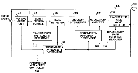
FIG.5 schematically shows the configuration of the
communication terminal 500 serving as the
transmitting station in the radio transmission
CA 02398932 2002-08-20
-12-
system of this embodiment.
The communication terminal 500 includes a
waiting queue unit 501 for accumulating the burst
signals to be transmitted, a transmission
availability controller 502, an encoder/interleaver
503, a modulator/amplifier 504, a transmitter-side
wave-splitter 505, an antenna 506, a transmission
path condition measurer 507 for measuring the radio
transmission path condition between the transmitting
station and the receiving station, and a
transmission power/rate determiner 508.
The transmission availability controller
502 includes a burst divider/combiner 509, a data
retriever 510, a transmission availability
determiner 511 for allowing or banning the burst
signal transmission on the basis of the measured
radio transmission path condition, and a
transmission unit length determiner 512 for
determining the transmission unit length as a
reference length for burst signal transmission.
Operation of the communication terminal
500 serving as the transmitting station of this
embodiment is now described. Input burst signals
are sequentially accumulated in the waiting queue
unit 501. When the burst divider/combiner 509
outputs a data retrieving request signal to the
waiting queue unit 501, the burst signal accumulated
in the waiting queue unit 501 is then retrieved and
output to the burst divider/combiner 509.
The burst signal, which is input to the
burst divider/combiner 509, is divided or combined
such that its length will match a predetermined
transmission unit length, as described in the above-
mentioned first aspect. In this context, the
predetermined transmission unit length is indicated
from a transmission unit length indication signal
that is output from the transmission unit length
CA 02398932 2002-08-20
-13-
determiner 512.
When the data retriever 510 outputs the
data retrieving request signal to the burst
divider/combiner 509, the data retriever 510
retrieves a burst signal generated after dividing or
combining, whose length equals to the transmission
unit length, and inputs it to the
encoder/interleaver 503.
Since the data retriever 510 outputs the
request signal to the burst divider/combiner 509 on
the basis of the transmission availability control
signal that is output from the transmission
availability determiner 511, switching between
transmission allowed and transmission not allowed of
the transmission unit-long burst signal is
controlled according to whether the signal is output
to the encoder or not. In other words, when the
transmission availability control signal from the
transmission availability determiner 511 indicates
"transmission allowed", the data retriever 510
retrieves the transmission unit-long burst signal
from the burst divider/combiner 509 and performs
some following transmission processes on it, while,
when the transmission availability control signal
indicates "transmission not allowed", the data
retriever 510 does not retrieve the transmission
unit-long burst signal from the burst
divider/combiner 509, and does not perform the
following transmission processes.
The transmission unit-long burst signal,
which is input to the encoder/interleaver 503, is
encoded and interleaved according to a transmission
rate that is determined by the transmission
power/rate determiner 508.
After the encoding and interleaving
processes, the transmission unit-long burst signal
is output to the modulator/amplifier 504, and is
CA 02398932 2002-08-20
-14-
modulated and amplified such that its transmission
power (when transmission power control is utilized)
and/or its transmission rate (when adaptive
modulation is utilized) equals the one determined by
the transmission power/rate determiner 508.
Alternatively, the transmission power and the
transmission rate may be measured and transmitted
from receiver-side as described later.
After the modulation and amplification
processes, the transmission unit-long burst signal
is output to the transmitter-side wave-splitter 505,
and radio-transmitted via the antenna 506 to the
receiving station.
On the other hand, a radio signal, which
is received via the antenna 506 from the receiving
station, is split and output to the transmission
path condition measurer 507 by the transmitter-side
wave-splitter 505, and then the radio transmission
path condition between the transmitting station and
the receiving station is measured. In this context,
the radio transmission path condition may be a state
quantity such as, for example, the measured
instantaneous value of path loss variation; the
transmission error rate; the transmission
throughput; the distance between the communication
terminal 500 and the receiving station; the power of
interference from other stations; the number of
other receiving stations that intend to receive
signals from the antenna 506 on the communication
terminal 500; the amount of information to be
transmitted; the average thereof; the desired
transmission time; the relative physical
relationship between the communication terminal 500
and the receiving station; or a combination thereof.
Radio transmission path condition
information, which is output by the transmission
path condition measurer 507, is input to the
CA 02398932 2002-08-20
-15-
transmission power/rate determiner 508. When the
transmission path condition is fine, smaller
transmission power and/or larger transmission rate
is output respectively to the encoder 503 and/or
modulator/amplifier 504, while, when the
transmission path condition is not fine, larger
transmission power and/or smaller transmission rate
is output respectively to the encoder 503 and/or
modulator/amplifier 504.
The radio transmission path condition
information, which is output by the transmission
path condition measurer 507, is also input to the
transmission availability determiner 511. On the
basis of such input radio transmission path
condition information and status information of the
burst signals waiting for transmission output by the
waiting queue unit 501, the transmission
availability determiner 511 determines to or not to
allow the burst signal transmission.
The transmission waiting status
information may be, for example, the amount of data
of the burst signals accumulated in the waiting
queue unit 501, or an average or maximal value of
passing time up to the present moment since each
burst signal is input to the waiting queue unit 501.
The above transmission availability
determination may be made, for example, by
calculating the time-average condition and the
instantaneous condition from the radio transmission
path condition information. After the calculation,
when the instantaneous condition is better than the
time-average condition, it is determined to allow
the transmission, while, when the instantaneous
condition is worse than the time-average condition,
it is determined not to allow the transmission.
Also, when it is observed from the transmission
waiting status information that the amount of data
CA 02398932 2002-08-20
-16-
or the waiting time of the burst signal waiting for
the transmission reaches a predetermined threshold,
it is determined to allow the transmission
regardless of whether the transmission path
condition is fine or not.
The above-described example is the case in
which the control based on the transmission waiting
status information always gets preference in the
transmission availability determination. However,
the control according to this embodiment is not
limited to such a case. For example, the above-
described threshold for the amount of data or
waiting time may vary on the basis of the radio
transmission path condition in order to take account
of both of the radio transmission path condition and
the transmission waiting status in transmission
control.
The above time-average condition may be,
for example, the median of receiving power in a
short period, and the above instantaneous condition
may be, for example, an instantaneous receiving
power. Also, the above-described case in which the
instantaneous condition is worse than the time-
average condition may be the case in which the
receiving power is caused to go down, for example,
due to fading.
On the basis of the above determination,
the transmission availability determiner 511
generates the transmission availability control
signal indicating the transmission allowed or the
transmission not allowed. This control signal is
output to the data retriever 510 and the
transmission unit length determiner 512. The
transmission availability control signal may be
generated and output each time the transmission
availability determiner 511 makes a decision or only
when the transmission availability changes (i.e.
CA 02398932 2002-08-20
-17-
from "allowed" to "not allowed", or from "not
allowed" to "allowed").
When the transmission availability control
signal is input to the transmission unit length
determiner 512, the determiner 512 determines the
transmission unit length on the basis of the control
signal, and then generates on the basis of the
determined transmission unit length the transmission
unit length indication signal, which is then output
to the burst divider/combiner 509.
In the above transmission unit length
determination, the control according to the above-
described first aspect is intended to be realized.
In a specific example, for example, a predetermined
threshold may be predefined to determine whether the
radio transmission path condition is fine or not.
Then the transmission availability is switched
between the transmission allowed and the
transmission not allowed in order to transmit the
signals only under the circumstances that the
condition is fine. A cycle of such switching is
observed, and the transmission unit length is varied
according to the length of the observed switching
cycle such that the ratio of the length of the
switching cycle to the transmission unit length (i.e.
the switching cycle length / the transmission unit
length) is kept constant, in order to set the
transmission unit length according to the radio
transmission path condition. This is detailed later.
The change of the transmission unit length may be
made periodically, or when the accumulated number of
times of switching reaches a threshold.
The configuration of the burst
divider/combiner 509 of this embodiment is now
described with reference to FIG.6. FIG.6
schematically shows the configuration of the burst
divider/combiner 509 of this embodiment.
CA 02398932 2002-08-20
-18-
As shown in FIG.6, the burst
divider/combiner 509 includes a storage 601 having a
plurality of data storing areas, and a transmission
unit generator 602. A burst signal read out into
the burst divider/combiner 509 is temporarily stored
in the storage 601, and then output to the
transmission unit generator 602 after being divided
if necessary.
In the transmission unit generator 602,
the attachment information is added to the burst
signal and the surplus is filled in to form a signal
as shown in FIG.4, which is then output to the data
retriever 510.
The receiving station according to this
embodiment is now described with reference to FIG.7.
FIG.7 schematically shows the configuration of the
communication terminal 700 serving as the receiving
station in the radio transmission system of this
embodiment.
The communication terminal 700 includes an
antenna 701, a receiver-side wave-splitter 702, a
channel splitter/demodulator 703, a
deinterleaver/decoder 704 for deinterleaving and
decoding the received signal, a burst
combiner/divider 705, a receiver-side transmission
path condition measurer 706, and a control signal
modulator/amplifier 707.
The channel splitter/demodulator 703
demodulates the received signal, and outputs
information associated with the transmission path
condition that can be observed at receiver-side to
the receiver-side transmission path condition
measurer 706. The above information may be, for
example, an instantaneous receiving power output
from the channel splitter/demodulator 703;
transmission throughput; power of interference from
other stations; or transmission error rate output
CA 02398932 2002-08-20
-19-
from the decoder 704. The receiver-side
transmission path condition measurer 706 outputs
such information or averaged or quantized data
thereof to the control signal modulator/amplifier
707.
An operation of the communication terminal
700 serving as the receiving station of this
embodiment is now described. The receiver-side
wave-splitter 702 outputs a radio signal, which is
received via the antenna 701, to the channel
splitter/demodulator 703.
In the channel splitter/demodulator 703,
the data channel received signal is demodulated, and
output to the deinterleaver/decoder 704, while the
information associated with the radio transmission
path condition between the transmitting station and
the communication terminal 700 obtained from the
received signal is output to the receiver-side
transmission path condition measurer 706.
In the deinterleaver/decoder 704, the
demodulated signal is deinterleaved and decoded to
recover the transmission unit-long burst signal,
which is then output to the burst combiner/divider
705. In the burst combiner/divider 705, the decoded
signal that is the transmission unit-long burst
signal is recovered into the original burst signal
on the basis of the information included in the
attachment information as shown in FIG.4.
The receiver-side transmission path
condition measurer 706, as described above, does
nothing to or averages or quantizes the information
associated with the transmission path condition that
is output from the channel splitter/demodulator 703,
and then outputs it to the control signal
modulator/amplifier 707. The control signal
modulator/amplifier 707 then modulates the
information input, and transmits it via the
CA 02398932 2002-08-20
-20-
receiver-side wave-splitter 702 and the antenna 701
to the transmitting station.
A transmission unit length determination
process according to this embodiment is now
described with reference to FIG.8. FIG.8 shows an
example of the process flow in the transmission unit
length determiner 512 of this embodiment.
In the example shown, the transmission
unit length is adjusted on the basis of the number
of times of switching the transmission availability
during a predetermined period that corresponds to a
result by multiplying the transmission unit length
by a constant.
When the transmission availability control
signal is input to the transmission unit length
determiner 512 and the transmission unit length
determination process starts, 0 is then assigned to
variables T and N to initialize (S801), where T
represents a counter indicating time, and N
represents a counter indicating the number of times
of switching between transmission allowed and
transmission not allowed in the transmission
availability control signal.
The following processes in S802-S814 are
repeated in a constant cycle T-delta. First, it is
monitored which the transmission availability
control signal indicates: transmission allowed or
transmission not allowed. Comparing with the
indication of the last transmission availability
control signal, it is then determined whether the
transmission availability is switched (S802). Only
when it is switched, N is incremented by 1(S803).
After the T-delta is added to T (S804), T
is compared with a predetermined observation period
(Tu*M) (S805), where Tu represents the transmission
unit length, and M represents a predetermined
constant. If T>=(Tu*M) is not satisfied, it is
CA 02398932 2002-08-20
-21-
considered that the predetermined observation period
is not passed and the procedure goes back to S802.
If the observation period is passed, the
procedure enters into the following transmission
unit length adjustment processes in S806-S809. A
lower threshold N_ and an upper threshold N+ are
employed for the number of times of switching the
transmission availability intended to be within a
period of the transmission unit length Tu, and M
times of each threshold is compared with N. If N is
smaller than M times of the lower threshold N- (M*N-
) ("YES" at S806), Tu is then extended (S809), while,
if N is larger than M times of the upper threshold
N+ (M*N+) ("YES" at S807) , Tu is then shortened
(S808).
The above extension and shortening
processes may be, for example, calculated using
addition, subtraction, multiplication or division
with an adjuster P (where P is a positive integer).
In other words, for example, in the extension
process in S809, the adjuster P is added to the
transmission unit length Tu or Tu is multiplied by P
(Tu <- Tu+P, or Tu <- Tu*P), while, in the
shortening process in S808, the adjuster P is
subtracted from the transmission unit length Tu or
Tu is divided by P (Tu <- Tu-P, or Tu <- Tu/P).
After the transmission unit length is thus
adjusted, the procedure then enters into the
following transmission unit length limitation
processes in S810-S813. A lower threshold Tumin and
an upper threshold Tumax are employed for the
transmission unit length Tu, and each threshold is
compared with Tu. If Tu is smaller than the lower
threshold Tumin ("YES" at S810 ), Tumin is then
assigned to Tu (S813), while, if Tu is larger than
the upper threshold Tumax ("YES" at S811) Tumax is
then assigned to Tu (S812).
- - ---- - -----
CA 02398932 2002-08-20
-22-
After the transmission unit length is thus
adjusted and limited, a final transmission unit
length is determined. The procedure then clears T
and N (S814), and goes back to S802 to perform the
same determination process for the next observation
period.
The flow of the burst division/combination
processes according to this embodiment is now
described with reference to FIG.9. FIG.9 shows an
example of the process flow in the burst
divider/combiner 509 of this embodiment.
When the procedure starts, 0 is assigned
to variables Nb and Ts (S901), where Nb represents a
serial number assigned to each burst signal, which
corresponds to the burst signal number 402 in FIG.4,
and Ts represents the length of an unprocessed part
of the burst signal stored in the storage 601.
The data storing area in the transmission
unit generator 602 is then cleared, and a value Tu
is assigned to a variable Tr (S902), where Tr
represents the length of free space of the data
storing area in the transmission unit generator 602,
and Tu represents the transmission unit length.
Ts is then compared with 0(S903). If Ts
does not equal to 0, the procedure goes to the
after-mentioned S909, while, if Ts equals to 0, the
burst divider/combiner 509 outputs the data
retrieving request signal to the waiting queue unit
501 (S904). If the burst divider/combiner 509
receives the burst signal from the waiting queue
unit 501 in response to the request ("Yes" at S905),
the procedure goes to the after-mentioned S908.
If the burst signal is not input at S905
("No" at S905), Tr is compared with Tu (S906). If
Tr does not equal to Tu, it is considered that the
burst signal or fragment is already stored in the
transmission unit generator 602, and the procedure
CA 02398932 2002-08-20
-23-
goes to the after-mentioned S915 to enter into the
output process in order to avoid causing
transmission delay of the stored burst signal or
fragment.
If Tr equals to Tu at S906, it is
considered that the burst signal or fragment is not
yet stored in the transmission unit generator 602,
and the procedure waits for the burst signal input
from the waiting queue unit 501 (S907).
When the burst signal is input from the
waiting queue unit 501, it is temporarily stored in
the storage 601, and its length Tpac is assigned to
Ts. Also, a new burst signal process starts, the
variable Nb is incremented by 1, and 1 is assigned
to a variable Nf (S908), where Nf represents a
serial number indicating a fragment number, which
corresponds to the fragment number 403 in FIG.4.
In the following processes in S909-S914,
the burst signal or fragment stored in the storage
601 is sent to the transmission unit generator 602.
First, a result by adding the length I of
the attachment information (c.f. FIG.4) to the
variable Ts is compared with Tr (S909). If
(Ts+I)=<Tr is satisfied, it is considered that the
total length of the data and the attachment
information is fitted in the free space in the
transmission unit generator 602, and the burst
signal or fragment temporarily stored in the storage
601 is sent to the transmission unit generator 602
without the division process (S910). Then, the
attachment information is added to the data, which
consists of, as shown in FIG.4, the burst signal
number Nb, the fragment number Nf, the data length
Ts, and the continuation identifier. In the case
without the division process, the continuation
identifier indicates "not continued".
A result by subtracting (Ts+I) from the
CA 02398932 2002-08-20
-24-
variable Tr, and 0 are then assigned respectively to
Tr and Ts (S911), because a space corresponding to
(Ts+I) in the free space of the transmission unit
generator 602 is filled.
Tr is then compared with a predetermined
threshold (Tu-Th) (S912), where the value Th is the
lower length of an effective part used as the data
or the attachment information in the transmission
unit length Tu. If Tr=<(Tu-Th) is not satisfied,
the procedure goes back to S904 to add the burst
signal or fragment to the transmission unit. If
Tr=<(Tu-Th) is satisfied, the procedure goes to S915
to enter into the transmission process for the
present transmission unit.
On the other hand, if (Ts+I)=<Tr is not
satisfied at S909, it is considered that total
length of the data and the attachment information is
not filled in the free space of the transmission
unit generator 602, and the burst signal or fragment
temporarily stored in the storage 601 is then
divided.
That is, the first (Tr-I)-long part from
the beginning of the burst signal or fragment stored
in the storage 601 is abstracted and sent to the
transmission unit generator 602, which adds the
attachment information (S913). In this case, the
continuation identifier 405 indicates "continued".
The variable Nf is then incremented by 1
and (Tr-I) is subtracted from Ts (S914), because the
(Tr-I)-long part of the data stored in the storage
601 is processed as a fragment.
In the following processes in S915-S917,
the transmission unit-long burst signal, which is
generated in the transmission unit generator 602, is
output to the data retriever 510.
First, an unused space (i.e. a surplus) of
the data storing area in the transmission unit
-------------
CA 02398932 2002-08-20
-25-
generator 602 is filled in with "0"s or "1"s (S915).
This surplus can be detected by the burst
combiner/divider 605 at receiver-side.
The procedure then waits for the data
retrieving request signal from the data retriever
510 (S916). When the request signal is input, the
transmission unit-long burst signal, which is
generated in the transmission unit generator 602, is
output to the data retriever 510 (S917).
The procedure for one transmission unit-
long burst signal is finished after the process in
the burst divider/combiner 509, and the procedure
goes back to S902.
Thus, according to this embodiment, before
being transmitted, the burst signals are
divided/combined to coordinate their lengths with
the transmission unit that is set on the basis of
the radio transmission path condition between the
transmitting station and the receiving station in
order to transmit them in units of the transmission
unit. Therefore, regardless of the lengths of the
burst signals, transmitting the burst signal under
the circumstances that the radio transmission path
condition is not fine can be avoided.
Also, since the transmission unit length
is updated each time the predetermined observation
time is passed regardless of the cycle of switching
between transmission allowed and transmission not
allowed, the transmission unit length is updated at
a proper frequency even when the switching cycle is
very long.
In this embodiment, if the indication of
the transmission unit length, which is output from
the transmission unit length determiner 512, is
provided to always represent one predetermined value,
the control according to the above-described third
aspect will be achieved.
CA 02398932 2002-08-20
-26-
Alternatively, the transmission unit
length may only take one of a predetermined
plurality of values in this embodiment. Thus, the
signal length of the transmission unit-long burst
signal, which is output from the data retriever 510,
can fall within the predetermined values,
simplifying the following encoding and interleaving
processes. In this case, the shortening and
extension processes of the transmission unit length
(S808 and S809 in FIG.8) are achieved by selecting
one-size longer or shorter transmission unit length.
Although this embodiment is described as a
case in which the fragment number Nf 403 is used as
a part of the attachment information, the present
invention is not limited to such a case. For
example, any other information indicating the
location of the fragment such as the number of bits
or bytes from the beginning of the original burst
signal or the results by dividing them by a
predetermined value may be used. Here, the
predetermined value may be, for example, a greatest
common divider of all possible values of the value
(Tu-I) in the transmission unit length Tu. When
such fragment location information other than the
fragment number is used, the fragment can be further
divided/combined at any location in the burst signal
to which it belongs. This enables that, for example,
even though the transmission unit length Tu is
changed when retransmitted by the automated
retransmission (ARQ) control, the fragment to be
retransmitted can be further divided/combined to
match a new transmission unit length Tu.
The radio communication system and its
burst signal transmitting method according to the
second embodiment of the present invention are now
described with reference to FIGs.10 and 11. This
embodiment basically has configuration and operation
CA 02398932 2002-08-20
-27-
similar to the ones of the first embodiment, however
it is intended to achieve not only the transmission
availability control according to the above-
described second aspect of the present invention but
also the one of the fourth aspect.
First, the configuration of the
communication terminal according to this embodiment
is described with reference to FIG.10. FIG.10
schematically shows the configuration of the
communication terminal 1000 serving as the
transmitting station included in the radio
transmission system according to this embodiment.
Components similar to the transmitting station of
the first embodiment (i.e. the communication
terminal 500 in FIG.5) have consistent reference
numbers, and are not detailed here for convenience.
Also, since the communication terminal serving as
the receiving station included in the radio
communication system according to this embodiment
has the same configuration and operation as the ones
of the receiving station of the first embodiment
(i.e. the communication terminal 700 in FIG.7), it
is not shown or detailed here for convenience.
The communication terminal 1000 of this
embodiment has a transmission availability
controller 1001 newly having a transmission
availability control signal switch 1002. The
transmission availability control signal switch 1002
normally outputs the transmission availability
control signal, which is output from the
transmission availability determiner 511, to the
data retriever 510 without any processing.
The transmission unit length determiner
1003 of this embodiment monitors the determined
transmission unit length. When the transmission
unit length becomes shorter, for example, than a
predetermined threshold, it is considered that the
CA 02398932 2002-08-20
-2$-
cycle of switching between the transmission allowed
period and the transmission not allowed period
becomes too short (i.e. the switching becomes too
frequent), and the transmission unit length
determiner 1003 outputs a control signal
(hereinafter referred to as a transmission
availability control suspending signal) indicating
the transmission availability control signal switch
1002 such that the transmission availability control
signal is not input to the data retriever 510 in
order to suspend the transmission availability
control.
When the transmission availability control
suspending signal is input, the transmission
availability control signal switch 1002 suspends the
output of the transmission availability control
signal from the transmission availability determiner
511 to the data retriever 510. As described in the
fourth aspect, during this suspension, the burst
signal may be always allowed for transmission, or
all transmission may be suspended. In the case in
which the burst signal can be transmitted while the
transmission availability control is suspended, the
transmission unit may have any length, preferably
being sufficiently long.
The transmission unit length determiner
1003 continues monitoring the transmission unit
length even during the suspension of the
transmission availability control. When the
transmission unit length becomes longer, for example,
than a predetermined threshold, it is considered
that the cycle of switching between the transmission
allowed period and the transmission not allowed
period becomes not too short (i.e. the switching is
not too frequent), and the transmission unit length
determiner 1003 outputs a control signal
(hereinafter referred to as a transmission
CA 02398932 2002-08-20
-29-
availability control restarting signal) indicating
to the transmission availability control signal
switch 1002 such that the transmission availability
control signal is input to the data retriever 510 in
order to restart the transmission availability
control.
When the transmission availability control
restarting signal is input, the transmission
availability control signal switch 1002 restarts to
output, as usual, the transmission availability
control signal from the transmission availability
determiner 511 to the data retriever 510.
The transmission unit length determination
process of this embodiment is now described with
reference to FIG.11. FIG.11 shows an example of the
process flow in the transmission unit length
determiner 1003 of this embodiment. Processes of
S1101-S1109 in FIG.11 are the same as the ones of
the first embodiment (S801-S809 in FIG.8), and are
not detailed here for convenience.
Upon being adjusted by the processes until
S1109, the transmission unit length is entered into
the following transmission unit length limitation
processes in S1110-S1119. First, the transmission
unit length Tu is compared with the lower threshold
TUmin (S1110) . If Tu is smaller than Tllmin. it is
determined whether a flag F equals 1(S1111), where
F represents which the last transmission
availability control indicates: the control
suspended or the control restarted, wherein F equals
to 1 when the transmission availability control is
suspended.
If F equals to 1 at Sllll, the procedure
finishes the transmission unit length limitation
process and goes to S1120. If F does not equal to 1,
it is considered that the transmission availability
control is active, and the transmission availability
CA 02398932 2002-08-20
-30-
control suspension signal is output to the
transmission availability control signal switch 1002
(S1112), while 1 is assigned to the flag F(S1113).
In the case in which the transmission is always
allowed during the suspension of the transmission
availability control, a predetermined arbitrary
length is output to the burst divider/combiner 509.
On the other hand, if Tu is not smaller
than Tumin at S1110, it is determined whether the
flag F equals to 1(S1115). If F does not equal to
1, the transmission availability control remains
active, and the procedure goes to the following
(S1118-) transmission unit length processing. If F
equals to 1, it is considered that the transmission
availability control is being suspended, and the
transmission availability control restart signal is
output to the transmission availability control
signal switch 1002 (S1116), while 0 is assigned to
the flag F (S1117).
While the transmission availability
control is thus active, the transmission unit length
Tu is then compared with the upper threshold Tumax
(S1118). If Tu is larger than the upper threshold
Tumax, TUmax is assigned to Tu (S1119) .
Thus, after the transmission availability
control suspension/restart processes, and the length
adjustment and limitation processes, the final
transmission unit length is determined. This
procedure clears T and N(S1120), and goes back to
S1102 to perform the same determination process for
the next observation period.
As described above, according to this
embodiment, under the circumstances that the
determination of the radio transmission path
condition is too frequently switched between better
and worse (i.e. the variation cycle is very short),
making processing too much and too complicated in
CA 02398932 2002-08-20
-31-
order to follow such fast variation can be avoided,
and the processes can be simplified.
Although this embodiment is described as
the one in which the transmission availability
control is suspended under the circumstances that
the variation cycle is very short, the transmission
availability control can be additionally or
alternatively suspended under the circumstances that
the variation cycle is very long, using
configuration and processes similar to the above-
described ones.
In other words, when the variation cycle
of the transmission path condition is very long, the
transmission unavailable period becomes long, and
thereby the transmission waiting time of the burst
signals to be transmitted, which are accumulated
during such period, also becomes long. Therefore,
by suspending the transmission availability control,
such transmission delays of the burst signals can be
reduced.
In this embodiment, if the transmission
unit length, which is output from the transmission
unit length determiner 512, is fixed, the control
according to the above-described third aspect will
be achieved as well.
Further, in the case in which the burst
signal may be transmitted while the transmission
availability control is suspended, a channel error
control code length and an interleaving code length
can be made longer by setting the transmission unit
length relatively long. This can reduce the
transmission path error rate, compared to the case
in which the transmission unit length is relatively
short.
The radio communication system and its
burst signal transmitting method according to the
third embodiment of the present invention are now
CA 02398932 2002-08-20
-32-
described with reference to FIGs.12 and 13. This
embodiment basically has configuration and operation
similar to the ones of the first or second
embodiment, however it is intended to determine the
transmission unit length additionally on the basis
of the transmission waiting status information
and/or media information of the burst signals. As
an example, the communication terminal and its
operation of this embodiment are herein described in
the case in which it is implemented based on the
communication terminal 500 (FIG.5) of the first
embodiment.
First, the configuration of the
communication terminal according to this embodiment
is described with reference to FIG.12. FIG.10
schematically shows the configuration of the
communication terminal 1200 serving as the
transmitting station included in the radio
transmission system according to this embodiment.
Components similar to the transmitting station of
the first embodiment (i.e. the communication
terminal 500 in FIG.5) have consistent reference
numbers, and are not detailed here for convenience.
Also, since the communication terminal serving as
the receiving station included in the radio
communication system according to this embodiment
has the same configuration and operation as the ones
of the receiving station of the first embodiment
(i.e. the communication terminal 700 in FIG.7), it
is not shown or detailed here for convenience.
In this embodiment, in addition to the
transmission availability control signal output from
the transmission availability determiner 511, the
transmission waiting status information output from
the waiting queue unit 501 and the media information
associated with the burst signal to be transmitted
are input to the transmission unit length determiner
CA 02398932 2002-08-20
-33-
1202.
In this context, the media information may
be, for example, information related to the amount
of information to be transmitted, information
related to the priority of transmission for each
burst signal provided from the upper layer, or
information related to acceptable delay time for
each burst signal.
The transmission unit length determiner
1202 sets the shorter transmission unit length when
more immediate transmission is required, for example,
when the amount of data waiting for transmission is
large, or when the transmission waiting time is long,
or when the acceptable delay time is short. The
transmission unit length determiner 1202 can thus
transmit the transmission unit-long burst signal
during a shorter transmission available period, in
order to increase the frequency of transmission and
transmit immediately the burst signal.
The transmission unit length determination
process of this embodiment is now described with
reference to FIG.13. FIG.13 shows an example of the
process flow in the transmission unit length
determiner 1202 of this embodiment. Processes other
than that of S1306 in FIG.13 (i.e. S1301-S1305 and
S1307-S1315) are the same as the ones of the first
embodiment (S801-S814 in FIG.8), and are not
detailed here for convenience.
When it is determined that the
predetermined observation time is passed in S1305,
the value of N is corrected on the basis of the
transmission waiting status information output from
the waiting queue unit 501 and the media information
associated with the burst signal to be transmitted.
In this correction, N may be, for example, increased
when the required delay time of the burst signal is
small or when the waiting time in the waiting queue
CA 02398932 2002-08-20
-34-
unit 501 is long, and decreased in other cases.
After this correction of N, as well as the
first embodiment, the transmission unit length
adjustment processes (S1307-S1310) and the
transmission unit length limitation processes
(S1311-S1314) are performed.
As described above, according to this
embodiment, the transmission unit length is
determined on the basis of, not only how long the
cycle of switching between the transmission allowed
and the transmission not allowed is, but also of the
transmission waiting status and the media
information provided from the upper layer of the
burst signal to be transmitted. Thus, the burst
signal can be transmitted using the effect of
increasing and decreasing of the amount of burst
signals that can be transmitted, for example, when
the burst signal waiting for transmission increases,
or when the acceptable delay time is changed.
In this embodiment, the transmission unit
length may be changed, for example, periodically, or
each time that a particular event occurs (e.g. the
waiting time of the burst signal in the waiting
queue unit 501 becomes longer than a predetermined
threshold).
Also, although, in this embodiment, as an
example, the communication terminal and its
operation of this embodiment is described in the
case in which it is implemented based on the
communication terminal 500 (FIG.5) of the first
embodiment, the communication terminal and its
operation of this embodiment can be implemented
based on the communication terminal 1000 (FIG.10) of
the second embodiment.
The radio communication system and its
burst signal transmitting method according to the
fourth embodiment of the present invention are now
CA 02398932 2002-08-20
-35-
described with reference to FIGs.14 and 15. This
embodiment basically has configuration and operation
similar to the ones of the first or second
embodiment, however it is intended not to be encoded
and interleaved in units of the transmission unit-
long signal but in units of the burst signal. As an
example, the communication terminal and its
operation in this embodiment are herein described in
the case in which it is implemented based on the
communication terminal 500 (FIG.5) of the first
embodiment.
FIG.14 schematically shows the
configuration of the communication terminal 1400
serving as the transmitting station included in the
radio transmission system according to this
embodiment, while FIG.15 schematically shows the
configuration of the communication terminal 1500
serving as the receiving station included in the
radio transmission system according to this
embodiment. Components similar to the ones of the
transmitting station and the receiving station of
the first embodiment (i.e. the communication
terminal 500 in FIG.5 and the communication terminal
700 in FIG.7) have consistent reference numbers, and
are not detailed here for convenience.
In the communication terminal 1400, an
encoder/interleaver 1401, which is provided between
the transmission availability controller 1402 and
the waiting queue unit 501, forwards the data
retrieving request signal for the waiting queue unit
501, which is output from the burst divider/combiner
1403, to the waiting queue unit 501 without
processing, and also encodes and interleaves the
burst signal retrieved from the waiting queue unit
501 in units of the burst signal.
Concurrently, in the communication
terminal 1500 serving as the receiving station, a
CA 02398932 2002-08-20
-36-
burst combiner/divider 1501 is provided subsequently,
to the channel splitter/demodulator 703, and a
deinterleaver/decoder 1502 is provided subsequently
to the burst combiner/divider 1501. The channel
splitter/demodulator 703 demodulates the
transmission unit-long burst signal. Then the burst
combiner/divider 1501 recovers the original burst
signal and the deinterleaver/decoder 1502
deinterleaves and decodes in units of the burst
signal.
As described above, according to this
embodiment, rather than encoding/decoding and
interleaving/deinterleaving the burst signals in
units of the transmission unit, the burst signal is
encoded/decoded and interleaved/deinterleaved,
before being divided and/or combined, in units of
the original burst signal. Therefore, even when the
transmission unit length is short, and thereby the
code length and the interleave length become short,
the effect of lowered error rate being reduced can
be avoided.
Also, although, in this embodiment, as an
example, the communication terminal and its
operation of this embodiment are described in the
case in which it is implemented based on the
communication terminal 500 (FIG.5) of the first
embodiment, the communication terminal and its
operation of this embodiment can be implemented
based on the communication terminal 1000 (FIG.10) of
the second embodiment.
The radio communication system and its
burst signal transmitting method according to the
fifth embodiment of the present invention are now
described with reference to FIGs.16. This
embodiment basically has configuration and operation
similar to the ones of the first, second, third, or
fourth embodiment, however it is intended to adjust
CA 02398932 2002-08-20
-37-
the transmission unit length by means of a
predetermined function regardless of how long the
transmission unit length is.
Since the transmitting station and the
receiving station of this embodiment have the same
configuration as the ones of the first, second,
third, or fourth embodiment, they are not shown or
described. The communication terminal and its
operation of this embodiment are in an example below
described in the case in which they are implemented
based on the communication terminals 500 (FIG.5) and
700 (FIG.7) of the first embodiment.
The transmission unit length determination
process of this embodiment is now described with
reference to FIG.16. FIG.16 shows an example of the
process flow in the transmission unit length
determiner of this embodiment.
In FIG.13, processes other than that of
S1606 are the same as the ones of the first
embodiment (S801-S809 and S814 in FIG.8), and are
not detailed here for convenience. In this
embodiment, in the transmission unit length
adjustment process of S1606 (corresponding to S806-
S809 in FIG.8), the transmission unit length is
adjusted to an appropriate value estimated by means
of a predefined function regardless of how long the
transmission unit length is.
In S1606, Q represents the number of times
of switching between transmission allowed and
transmission not allowed intended to be within the
period of the transmission unit length Tu, and a
result by multiplying the observation time (Tu*M) by
(Q/N) is assigned to Tu for adjustment.
As described above, according to this
embodiment, the transmission unit length is
determined on the basis of an arbitrary value rather
than of the previous transmission unit length.
CA 02398932 2002-08-20
-38-
Therefore, it can immediately increase or decrease
the transmission length in order to avoid occurring
longer delay even when the variation cycle of the
transmission path condition rapidly varies.
Alternatively, in the process in S1606, it
is possible to pre-hold a look-up table representing
a predetermined relationship between an old Tu and a
new Tu and to obtain the new Tu by making reference
to the table rather than the above calculation, in
order to simplify the processing.
Also, in this embodiment, if the
transmission unit length Tu is limited to a few
predetermined values, the new Tu may be cut up or
cut down in S1606.
The radio communication system and its
burst signal transmitting method according to the
sixth embodiment of the present invention are now
described with reference to FIG.17. This embodiment
basically has configuration and operation similar to
the ones of the first, second, third, or fourth
embodiment, however it is intended to adjust the
transmission unit length on the basis of time
required for reaching a predetermined number of
times of switching between transmission allowed and
transmission not allowed, rather than of the
observation time.
Since the transmitting station and the
receiving station of this embodiment have the same
configuration as the ones of the first, second,
third, or fourth embodiment, they are not shown or
described. The communication terminal and its
operation of this embodiment are in an example below
described in the case in which they are implemented
based on the communication terminals 500 (FIG.5) and
700 (FIG.7) of the first embodiment.
The transmission unit length determination
process of this embodiment is now described with
CA 02398932 2002-08-20
-39-
reference to FIG.17. FIG.17 shows an example of the
process flow in the transmission unit length
determiner of this embodiment.
In FIG.17, processes in S1701-S1704 and
S1710-S1714 are the same as the ones of the first,
second, third, or fourth embodiment, and are not
detailed here for convenience.
After switching between transmission
allowed and transmission not allowed, it is
determined whether N reaches a predetermined Nmax
(S1705).
If N reaches Nmax, T is then compared with
a predetermined lower threshold T_ and a
predetermined upper threshold T+. If T is smaller
than T_ ("YES" at S1706), the transmission unit
length is shortened, while, if T is larger than T+
("YES" at S1707), the transmission unit length is
extended.
The above increase/decrease process may be
implemented by an arbitrary method, such as by
adding, subtracting, multiplying, or dividing by a
predetermined value, or by a predetermined function
of T and N.
As described above, according to this
embodiment, when the number of times of switching
between transmission allowed and transmission not
allowed reaches the predetermined value (e.g. Nmax in
this example), the transmission unit length is
adjusted. Therefore, even when the cycle of
switching is long, and thereby the observed number
of times of switching N is low, degrading the
accuracy of updating the transmission unit length Tu
can be avoided.
Although, in this embodiment, as an
example,-the communication terminal and its
operation of this embodiment are described in the
case in which it is implemented based on the
CA 02398932 2002-08-20
-40-
communication terminal 500 (FIG.5) of the first
embodiment, the communication terminal and its
operation of this embodiment can be implemented
based on the communication terminal of the second,
third, or fourth embodiment.
The seventh embodiment of the present
invention is now described with reference to
FIGs.18-20. This embodiment is intended to
implement the above-described first aspect. This
embodiment has configuration similar to the one of
the fourth embodiment, however it is intended not to
determine or set the transmission unit length, but
to divide and/or combine the burst signals
adaptively for the transmission available period in
order to transmit the burst signals from when the
transmission path condition becomes fine until when
it becomes not fine.
The control of this embodiment is now
outlined with reference to FIG.18. FIG.18
schematically shows the outline of the burst signal
processing of this embodiment. It is here assumed
that there is, for example, a burst signal 1801 as
shown in FIG.18(a). This embodiment employs
modification of the above-described fifth aspect,
that is, it adds only a burst signal length 1802
(corresponding to the data length 404 in FIG.4) to
the burst signal 1801 as the attachment information.
The attachment information is thus simplified
because, as detailed later, the transmission unit
length is not set and the burst signals are not
divided or combined.
It is here assumed that the transmission
available periods, where it is determined that the
radio transmission path condition is fine, are
defined as periods 1803a-1803c shown in FIG.18(c).
The burst signal 1801 is divided in conformity to
the periods 1803a-1803c into the transmission units
CA 02398932 2002-08-20
-41-
1804a-1804c as shown in FIG.18(d). Then, the
transmission unit 1804a, the transmission unit 1804b,
and the transmission unit 1804c are respectively
transmitted during the period 1803a (from tll to t12)
the period 1803b (from t13 to t14) , and the period
1803c (from t15 to t16) .
In this case, in connection with the
transmission available period used for the burst
signal transmission, terminal signals 1805 are
transmitted at the end of the transmission available
period (t12 and t14 in the example shown) and the
beginning of the transmission available period (t13
and t15 in the example shown) . The terminal signal
1805 representing that the burst signal is cut along
the way, may be, for example, characterized in
arrangement of data and distinguished from the burst
signal 1801 and the burst signal length 1802. The
terminal signal can inform the receiving station
that there is a following transmission unit.
Alternatively, a pair of the terminal signals to be
coupled in order to recover the original burst
signal (the pair of the terminal signals 1805a and
1805b, and the pair of the terminal signals 1805c
and 1805d, in the example shown) may be
distinguished from other pairs.
The configuration of the communication
terminal of this embodiment is now described with
reference to FIG.19. FIG.19 schematically shows the
configuration of the communication terminal 1900
serving as the transmitting station included in the
radio transmission system according to this
embodiment. Components similar to the ones of the
transmitting station of the fourth embodiment (i.e.
the communication terminal 1400 in FIG.14) have
consistent reference numbers, and are not detailed
here for convenience.
The transmission availability controller
CA 02398932 2002-08-20
-42-
1901 of this embodiment includes only the
transmission availability determiner 511, and a data
retriever/divider 1902 having a memory capable of
internally storing data. The data retriever/divider
1902 retrieves the burst signal from the
encoder/interleaver 1401, and divides and outputs it
to the modulator/amplifier 504, on the basis of the
transmission availability control signal that is
output from the transmission availability determiner
511.
The transmission availability control of
this embodiment is now described with reference to
FIG.20. FIG.20 shows an example of the process flow
in the data retriever/divider 1902 of this
embodiment.
Upon starting the process, the data
retriever/divider 1902 outputs the data retrieving
request signal to the encoder/interleaver 1401
(S2001). Upon the burst signal from the
encoder/interleaver 1401 being input, the data
retriever/divider 1902 adds the burst signal length
1802 (c.f. FIG.18) information to the head of the
burst signal, and stores the burst signal and the
burst signal length information added thereto in the
internal memory (S2002).
The data retriever/divider 1902 then waits
for the transmission availability control signal
input from the transmission availability determiner
511 (S2003). If it is input, the data
retriever/divider 1902 outputs only a portion of
untransmitted part of the burst signal and the burst
signal length information added thereto (hereinafter
collectively referred to as a burst signal) stored
in the internal memory to the modulator/amplifier
504 (S2004). This portion may be defined in units
of, for example, a symbol, a bit, or a slot, and may
be set arbitrarily.
CA 02398932 2002-08-20
-43-
It is then determined whether all burst
signals stored in the internal memory are output to
the modulator/amplifier 504 or not (S2005). If so,
the procedure goes back to S2001, and enters into
the process for the next burst signal.
If the burst signal still remains in the
internal memory ("NO" at S2005), the data
retriever/divider 1902 then waits for the
transmission availability control signal indicating
transmission not allowed that is input from the
transmission availability determiner 511 (S2006).
If there is no indication of transmission not
allowed ("NO" at S2006), the procedure goes back to
S2004, and the data retriever/divider 1902 outputs
the next portion.
If the transmission availability control
signal indicates that the transmission is not
allowed ("YES" at S2006), the data retriever/divider
1902 suspends outputting the burst signals to the
modulator/amplifier 504 at that time, and also
outputs the terminal signal to the
modulator/amplifier 504 in order to inform the
receiving station that the transmission is suspended
along the way of one burst signal (S2007).
Subsequently, while the transmission is
suspended, the data retriever/divider 1902 waits for
the transmission availability control signal
indicating that the transmission is allowed, which
is input from the transmission availability
determiner 511 (S2008). If it is input, the data
retriever/divider 1902 again outputs the terminal
signal to the modulator/amplifier 504 (S2009), and
the procedure goes back to S2004 and continues the
transmission process.
As described above, according to this
embodiment, the transmission unit determination and
setting processes can be dispensed with to use
CA 02398932 2002-08-20
-44-
effectively the transmission available periods for
the burst signal transmission.
Alternatively, this embodiment can be
implemented along with the transmission availability
control according to the above-described fourth
aspect.
The eighth embodiment of the present
invention is now described with reference to FIG.21.
This embodiment has configuration similar to any one
of the configurations of the first through seventh
embodiments, however it is intended that the
receiving station determines the radio transmission
path condition and transmits it to the transmitting
station. FIG.21 schematically shows an example of
the configuration of the receiver-side transmission
path condition measurer of the communication
terminal 2100 serving as the receiving station
included in the radio transmission system of this
embodiment.
The receiver-side transmission path
condition measurer 2100 includes a receiver-side
transmission availability determiner 2101, and a
transmission unit length determiner 2102.
The receiver-side transmission
availability determiner 2101 calculates, on the
basis of the radio transmission path condition
information that is output from the channel
splitter/demodulator, the time-average information
such as the median of the short-term receiving power,
and the instantaneous information such as the
instantaneous receiving power. If the instantaneous
condition is better than the time-average condition,
the receiver-side transmission availability
determiner 2101 generates the transmission
availability control signal indicating that the
transmission is allowed, while it generates the
transmission availability control signal indicating
CA 02398932 2002-08-20
-45-
that the transmission is not allowed in the other
cases. The receiver-side transmission availability
determiner 2101 then outputs each control signal to
both of the control signal modulator/amplifier and
the transmission unit length determiner 2102.
The transmission unit length determiner
2102, which may have the same configuration and
operation as any one of the transmission unit length
determiners of the above-described embodiments,
determines the transmission unit length on the basis
of the transmission availability control signal that
is output from the receiver-side transmission
availability determiner 2101, and outputs the
transmission unit length indication signal
indicating the determined transmission unit length
to the control signal modulator/amplifier.
The control signal modulator/amplifier
radio-transmits each input signal to the
transmitting station as a transmission path
condition measured at the receiver-side, and
determined or provisionally-determined transmission
availability control signal and transmission unit
length. The transmitting station utilizes the
received information determined by the receiving
station as a parameter for the transmission
availability control. The transmitting station may
perform the control on the basis of only the
information from the receiving station, or of both
the receiver-side information and the transmitter-
side information.
As described above, according to this
embodiment, since the transmission availability
control signal indicating transmission allowed or
transmission not allowed and the transmission unit
length are determined or provisionally-determined at
the receiving station, and are provided to the
transmitting station, information to be transmitted
CA 02398932 2002-08-20
-46-
to the transmitting station can be reduced compared
with the case in which all information of the
transmission path condition has to be transmitted.
In particular, this effect can be enhanced in the
case in which the information is transmitted only
when the transmission availability that the
transmission availability control signal indicates
is changed.
If the information of the transmission
path conditions of a plurality of the transmitting
stations are input to the receiver-side transmission
path condition measurer 2100, a transmitting and
receiving system can be easily made that allows,
among the plurality of transmitting stations, only
ones staying under the fine transmission path
condition to transmit the burst signal.
Alternatively, only one kind of
information from the above-described information
(the transmission availability control signal
indicating the transmission allowed or the
transmission not allowed, and the transmission unit
length) may be transmitted.
Also, in the case in which the
transmitting station performs the transmission
availability control on the basis of only the
receiver-side information, the transmitting station
may dispense with components and/or functionality to
determine such information.
As described above, according to the first
through eighth embodiments of the present invention,
in the burst signal transmission availability
control, transmitting the burst signal under the
circumstances that the transmission path condition
in not fine can be avoided.
In the division/combination process in
every above embodiment, by performing only the
division process, transmitting the burst signal
CA 02398932 2002-08-20
-47-
under the circumstances that the transmission path
condition is not fine can be avoided. However, by
performing the combination process together, the
transmission available period can be utilized more
effectively, enabling an increase in the efficiency
of transmission. Of course, only the combination
process may be performed under the circumstances
that the burst signal length is always shorter than
the transmission unit length.
The present invention is not limited to
the specifically disclosed embodiments, and
variations and modifications may be made without
departing from the scope of the invention.