Note: Descriptions are shown in the official language in which they were submitted.
CA 02399156 2002-08-02
WO 01/59602 PCT/USO1/04698
NESTED RELATIONAL DATA MODEL
COPYRIGHT NOTICE
A portion of the disclosure of this patent document contains material that
is subject to copyright protection. The copyright owner has no objection to
the facsimile
reproduction by anyone of the patent document or the patent disclosure as it
appears in
the Patent and Trademark Office patent file or records, but otherwise reserves
all
copyright rights whatsoever.
FIELD OF THE INVENTION
The present invention relates to information management in general and
more particularly to methods for using Nested Relational Data Models (NRDMs)
to
manage information.
BACKGROUND OF THE INVENTION
Information is commonly managed in units of documents. For example,
sales, distribution and manufacturing information might be contained within
documents
such as sales invoices or orders. Increasingly, documents pass between parties
in
electronic form, in a process generally referred to as EDI (Electronic Data
Interchange).
In electronic form, the documents are not limited to the text and images shown
on the
printed page, but can include formatting and "metadata" (data about the data).
One
example of a format for an electronic document that contains metadata is the
Extended
Markup Language (XML).
Several products on the market allow mapping of XML documents to SQL
tables or vice versa and several products on the market allow mapping of EDI
documents
to relational tables or vice versa, but these products typically require
procedural
specifications of how to perform the conversion, such as programming code.
Traditional
Relational Database Management Systems (RDMS's) such as described by Date or
Unman or implemented by Oracle, IBM, Microsoft and others as well as
distributed
databases as described in Ceri or U.S. Patent Nos. 5,884,310 and 5,596,744,
implement
declarative transformations of relational data.
A class of systems called intelligent gateways (such as Sybase's
OmniServer system) allow declarative rules to be transparently applied to
heterogeneous
relational databases. Another class of systems called Replication Servers
(such as
CA 02399156 2002-08-02
WO 01/59602 PCT/LTSO1/04698
described by U.S. Patent No. 5, ~ 37,601 or implemented as Sybase's
Replication Server,
Oracle's Replication Server, or tie like) can provide homogeneous or
heterogeneous data
replication.
Additional class of systems called the ETL (Extraction, Transformation,
Loading) systems such as Microsoft DTS, Informatica PowerMart and D2K Tapestry
provide extraction, transformation and loading of heterogeneous data between
relational
database systems. Some of these products support converting hierarchical files
into a
relational form by "flattening" the hierarchical files, making multiple passes
through a
hierarchical file and, at each pass, pulling out different parts of the
hierarchy.
Yet another class of systems that address mapping of relational data to a
programming object, as exemplified by U.S. Patent Nos. 6,175,837, 6,163,781,
6,134,559, 5,907,846, 5,873,093, 5,832,498, or products from Persistence, Bea
and
others. This class of tools maps persistently stored relational data to an
object-oriented
memory representation as well as mapping the data from an object-oriented
memory
representation to a set of persistent relational tables.
Another class of prior art exists that provides object-oriented access to
non-relational databases, as described in U.S. Patent Nos. 5,799,313,
5,778,379, and
5,542,078. This class of systems addresses the mapping of data from
hierarchical
databases such as IMS, object oriented databases and relational databases to
an
object-oriented programming object or database.
Considerable research has been done on Nested Relational Data Models as
described in , "Lecture Notes in Computer Science Volume 595: M. Levene - The
Nested Universal Relation Database Model" and , "Lecture Notes in Computer
Science Volume 361: S. Abiteboul et al. - Nested Relations and Complex Objects
in
Databases". That research focused mainly on defining the data model and
specific
operations on it.
It is known to graphically map disparate schemas to each other. See, for
example, U.S. Patent Nos. 5,850,631 and 5,806,066. It is also known to map
data
between different structures. See for example, U.S. Patent Nos. 5,627,972 and
5,119,465.
SUMMARY OF THE INVENTION
In one embodiment of data processing system according to the present
invention, hierarchical documents or hierarchical messages are mapped to a
Nested
Relational Data Model to allow for transformation and manipulation using
declarative
2
CA 02399156 2002-08-02
WO 01/59602 PCT/LTSO1/04698
statements. The resulting nested data can be converted to a relational format
and mapped
to multiple relational tables, and/or converted from a nested relational
format to an
external hierarchical format, such as XML.
The system can specify and execute declarative rules to extract, transform,
integrate, load and update hierarchical and relational data. The system can
also be used
for extending documents with relational and non-relational data and applying
updates
based on these documents to relational database targets. The system can also
be used for
mapping Nested Relational Data to function calls that accept tables as
parameters and
return multiple scalar and table parameters as output.
BRIEF DESCRIPTION OF THE DRAWINGS
Fig. 1 shows a table that is related to a single row of another table.
Fig. 2 shows the data of Fig. l, organized as multiple rows in a single
table.
Fig. 3 shows the data of Fig. 1, organized as multiple tables related by a
join.
Fig. 4 illustrates multiple levels of nested tables contained in one column.
Fig. 5 illustrates a more general example of multiple levels of nested tables
contained in more than one column.
Fig. 6 is a block diagram of a database system according to one
embodiment of the present invention.
Fig. 7 illustrates schema relating to nested tables; Fig. 7A shows input
tables and Fig. 7B shows an output schema.
Fig. 8 illustrates a process of grouping values across nested tables.
Fig. 9 illustrates a process of unnesting data; Fig. 9A shows how a table
with a nested table would be unnested into a cross-product of the parent table
and a child
(nested) table; Fig. 9B illustrates unnesting into separate tables; Fig. 9C
illustrates
unnesting at multiple levels.
Fig. 10 illustrates a case where unnesting might produce unintended
effects.
Fig. 11 graphically illustrates an unnesting process and its effects on a
query.
Fig. 12 illustrates a process of converting a DTD to tables.
Fig. 13 illustrates the XML encoding of a DTD definition.
3
CA 02399156 2002-08-02
WO 01/59602 PCT/USO1/04698
Fig. 14 illustrates various real-time data flows.
Fig. 15 illustrates an operation of joining two inputs in a query.
Fig. 16 illustrates real-time data flows that use supplementary information.
Fig. 17 illustrates data flows depending on cached values.
Fig. 18 illustrates branching data flows based on rules.
Fig. 19 is an illustration of a complex real-time data flow.
Fig. 20 is an illustration of a GUI for specifying a data flow.
Fig. 21 is a block diagram of a schema conversion system.
Figs. 22-26 are tables illustrating various aspects of an NRDM system.
DESCRIPTION OF THE SPECIFIC EMBODIMENTS
In a specific embodiment a Nested Relational Data Model (NRDM) is
designed to support hierarchical and relational components used to represent
business
data. Business documents are typically hierarchical with multiple repeating
sets. For
example, an order contains a set of repeating line items. It may also have a
set of
customers associated with it.
Business documents used to exchange data between software systems
within an enterprise or between enterprises need to be represented as complex
hierarchical documents. The industry and the research community use well-known
representations such as EDI and XML to capture and represent such documents.
The
system described herein provides methods for mapping such documents to a
Nested
Relational format, methods for transforming and manipulating of these
documents
represented using the Nested Relational Data Model, converting such documents
to
relational format and mapping them to multiple relational tables, and a method
of
converting the data in a nested relational format back to an external
hierarchical format
such as XML.
The system provides a method to apply declarative rules to map the
hierarchical (e.g., XML or EDI) data to relational tables and vice versa;
declarative rules
to enrich hierarchical data with data from other relational or hierarchical
sources;
declarative rules to perform mufti-stage transformations. The system allows
declarative
transformations to be applied to hierarchical data, and the ability to
transparently apply
rules to heterogeneous databases and files; as well as in the ability to apply
mufti-stage
transformations. Delcarative specifications (such as SQL) describe what to do
with data,
as opposed to procedural specifications (such as C++ code) that described how
to do it.
4
CA 02399156 2002-08-02
WO 01/59602 PCT/USO1/04698
"Nested data" is data in a table that is related to a single row of another
table. Sales orders are often presented using nesting: the line items in a
sales order are
related to a single header. For a table of sales order headers, each row
includes its own
table of line items. An example of this is shown in Fig. 1. Of course, the
same data could
be represented without nested tables. For example, the data could be
represented as
multiple rows in a single table as shown in Fig. 2, or as multiple tables
related by a join as
shown in Fig. 3.
One source of data for a nested table is the result of a query using the
values in the related row in the parent table. As used herein, "parent table"
refers to a
table within which another table is nested and "child table" or "nested table"
refers to a
table that is nested in a column of a parent table. A nested table is said to
have a
relationship with the table within which it is nested and where levels are
associated with
tables, a parent table would have a level that is designated with a number one
higher than
the child tables nested in that parent table. For example, Fig. 4 shows a
parent table 10, a
nested (child) table 12 one level below table 10 and nested tables 14(a)-(b)
that are nested
in table 12 and are two levels below table 10.
Preferably, a unique instance of each nested table exists for each row at
each level of a relationship. As illustrated in Fig. 5, each row at each level
can have any
number of columns containing nested tables.
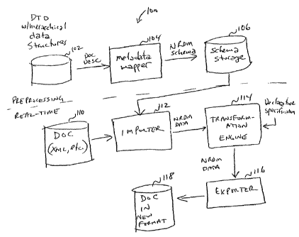
Fig. 6 shows various aspects of a database system 100 that handles NRDM
data. System 100 is shown comprising a metadata mapper 104 that maps DTD 102
w/hierarchical structures to NRDM schema that are stored in schema storage
106. These
components are shown as being part of a preprocessing section, with other
portions being
part of a real-time section, but it should be understood that all of the
process or none of
the processing might be done in real-time without departing from the essence
of the
invention. Notwithstanding that caveat, the descriptions below reference an
example
wherein DTDs are converted to NRDM schema and stored and documents are
converted
by system 100 in real-time after such conversion.
One such real-time process involved a document 110 being passed to an
importer, then to a transformation engine (TE) 114 and an exporter 116 to
result in a
document in a new format 118 (in some cases, the formats of document 110 and
document 118 might be the same, but some transformation has occurred).
Document 110
is a structured document, such as an XML document, an HTML page, a document
having
other structure, or other structured data object.
5
CA 02399156 2002-08-02
WO 01/59602 PCT/USO1/04698
Importer 112 cor verts the document into NRDM data so that TE 114 can
operate on data in the NRDM sl ace, thus simplifying many transform
operations, as
described below. TE 114 accep a data in NRDM format as its input and outputs
data in
NRDM format. Of course, data in NRDM (Nested Relational Data Model) format
need
not have nested data (for example, if the input data can be structured such
that nesting is
not needed). Because TE 114 operates on NRDM structures, the transformations
performed by TE 114 can be expressed simply as a declarative specification,
thus greatly
simplifying the process of transforming complex data. In effect, importer 112
converts a
hierarchical document into a relational database form to which declarative
statements can
be applied.
Exporter 116 exports the data in a suitable form, such as XML documents,
relational tables or flat files.
Data Flows
In a graphical interface used to build data flows and/or nested data
structures, such as the ActaWorksTM system developed by Acta, Inc. structures
of nested
data in input and output schemas of sources, targets, and transforms in data
flows are
presented to a designer. An example of an input schema 60 is shown in Fig. 7A
and an
example of an output schema 62 is shown in Fig. 7B. Input schema 60 shows a
table A
that has columns columnl, column2 and a column for a nested table B, which in
turn has
columns column4 and columns. Input schema 60 also shows a table Z that has
columns
columnl l, columnl2 and a column for a nested table Y, which in turn has
columns
columnl4 and columnl5. In Fig. 7A, and others, nested tables appear with a
table icon
paired with a plus sign, which indicates that the object contains columns (a
minus sign
indicates that the object is open and if it has columns, those columns are
visible.
In a relational database system (RDS) using a declarative language such as
SQL, a query transform might take the form of a SELECT statement that is
executed by
the RDS. When working with nested data in an nested relational data model
(NRDM)
system according to some aspects of the present invention, the query can
specify
SELECTS at each level of a relationship defined in the output schema. Thus,
while a
SELECT statement might be constrained to include only references to relational
data sets,
a query that includes nested data might include a SELECT statement to define
operations
on each table in the output--each context for the input data set is
transformed.
In such an NRDM system, the FROM clause descriptions and the behavior
of the query are the same with nested data as with relational data, but the
new interface of
6
CA 02399156 2002-08-02
WO 01/59602 PCT/USO1/04698
contexts allows the data flow designer to distinguish multiple SELECTs from
each other
within a single query. At any context, the FROM clause can contain any top-
level table
from the input or any table that is a column of a table in the FROM clause of
the next
higher context.
When rows of one table (a child table) are nested inside another table (a
parent table), the data set produced in the nested table is the result of a
query against the
first table using the related values from the second table. For example, if
sales
information is available as a header table and a line-item table, the sales
information can
be organized as a parent table of header information and a child table
containing line-item
data here the line-items are nested under the header table. The line items for
a single row
of the header table are equal to the results of a query including the order
number, as might
be found using the following statement:
SELECT * FROM LineItems
IS WHERE Header.OrderNo = LineItems.OrderNo
Correlation can be used to construct a nested table from columns from a
higher-level context. In a nested-relational model, the columns in a nested
table are
implicitly related to the columns in the parent row. To take advantage of this
relationship, the parent table can be used in the construction of the nested
table. The
higher-level column is a correlated column. Including a correlated column in a
nested
table may serve at least two purposes: 1 ) the correlated column is a key in
the parent table
and 2) making the correlated column an attribute in the parent table.
Including the key in
the nested table allows for the maintenance of you a relationship between the
two tables
after converting them from the nested data model to a relational model.
Including the
attribute in the nested table allows for the use of the attribute to simplify
correlated
queries against the nested data.
Correlated columns can include columns from the parent table and any
other tables in the FROM clause of the parent table. If the correlated column
comes from
a table other than the immediate parent, the data in the nested table includes
only the rows
that match both the related values in the current row of the parent table and
the value of
the correlated column.
Values can be grouped across nested tables. Thus, when a statement
includes a Group By clause for a table with a nested table, the grouping
operation
combines the nested tables for each group. For example, to assemble all the
line items
7
CA 02399156 2002-08-02
WO 01/59602 PCT/USO1/04698
included in all the orders for each state from a set of orders, the designer
would set the
Group By clause in the top-level of the data set to the state column
(Order.State) and
create an output table that includes State column (set to Order.State) and
LineItems nested
table. The result of such an operation might result with the table shown in
Fig. 8. The
result is a set of rows (one for each state) that has the State column and the
LineItems
nested table that contains all the LineItems for all the orders for that
state.
Nested data can also be unnested. When loading a data set that contains
nested tables into a relational (non-nested) target, the nested rows will be
unnested. Take,
for example, a message containing a sales order that uses a nested table to
define the
relationship between the order header and the order line items. To load the
data into
relational tables, the mufti-level must be unnested. Unnesting a table
produces a
cross-product of the top-level table (parent) and the nested table (child), as
shown in Fig.
9A. Different columns from different nesting levels might be loaded into
different tables.
A sales order, for example, may be flattened so that the order number is
maintained
separately with each line item and the header and line item information loaded
into
separate tables, as shown in Fig. 9B.
Any number of nested tables can be unnested at any depth. No matter how
many levels are involved, the result of unnesting tables is a cross product of
the parent
and child tables. When more than one level of unnesting occurs, the inner-most
child is
unnested first, then the result--the cross product of the parent and the inner-
most child--is
then unnested from its parent, and so on to the top-level table, creating the
result shown in
Fig. 9C.
Unnesting all tables (cross product of all data) may not produce the results
intended. For example, if multiple customer values are included in an order,
such as
ship-to and bill-to addresses, flattening a sales order by unnesting customer
and line item
tables produces rows of data that may not be useful for processing the order.
This is
illustrated in Fig. 10. Using the GUI, the specification of the data flow is
shown in Fig.
11.
A DTD (document type definition) describes the data schema of an XML
message or file. Real-time data flows read and write XML messages based on a
specified
DTD format. One DTD can describe multiple XML sources or targets. Batch data
flows
can read and write data to files based on a specified DTD format.
DTDs can be imported into the NRDM system, either directly or by
importing an XML document that contains a DTD. During import, the NRDM system
CA 02399156 2002-08-02
WO 01/59602 PCT/USO1/04698
converts the structure defined in the DTD into an internal nested-relational
data model.
Elements below the root-level that contain other elements become nested tables
and
elements that do not contain other elements become columns. Attributes become
columns in the corresponding element's schema.
The NRDM system applies the following rules to convert the DTD to
tables, columns, and nested tables:
- Any element that contains PCDATA only and no attributes becomes a column.
- Any element with attributes or other elements (or in mixed format) becomes a
table.
- An attribute becomes a column in the table corresponding to the element it
supports.
- Any occurrence of choice operators is converted to strict ordering.
- Any occurrence of optional operators is converted to strict ordering.
- Any occurrence of ()* or ()+ becomes a table with an internally generated
name--an
implicit table.
After these rules have been applied, the NRDM system optimizes the
format using two more rules, except where doing so would allow more than one
row at
the root element:
- If an implicit table contains one and only one nested table, then the
implicit table can
be eliminated and the nested table can be attached directly to the parent of
the implicit
table. For example, the SalesOrder element might be defined as follows in the
DTD:
<!ELEMENT SalesOrder (Header, LineItems*)>
When converted, the LineItems element with the zero or more operator would
become an implicit table under the SalesOrder table. The LineItems element
itself
would be a nested table under the implicit table, as shown in Fig. 12A.
Because
the implicit table contains one and only one nested table, the format would be
optimized to remove the implicit table, as shown in Fig. 12B.
- If a nested table contains one and only one implicit table, then the
implicit table can
be eliminated and its columns placed directly under the nested table. For
example, the
nested table LineItems might be defined as follows in the DTD:
<!ELEMENT LineItems (ItemNum, Quantity)*>
When converted, the grouping with the zero or more operator would
become an implicit table under the LineItems table. The ItemNum and Quantity
elements
would become columns under the implicit table, as shown in Fig. 12C. Because
the
9
CA 02399156 2002-08-02
WO 01/59602 PCT/USO1/04698
LineItems nested table containe d one and only one implicit table, it would be
optimized
to remove the implicit table, as shown in Fig. 12D.
If the DTD contains a~n element that uses an ancestor element in its
definition, the definition of the ancestor can be expanded for a fixed number
of levels.
For example, given the following definition of element "A":
A: B, C
B: E, F
F : A, H
The system produces a table for the element "F" that includes an expansion of
"A." In this
second expansion of "A," "F" appears again, and so on until the fixed number
of levels.
In the final expansion of "A," the element "F" appears with only the element
"H" in its
definition.
Real-Time Sources
A real-time source in a real-time data flow determines the message that the
real-time data flow will process. The source object represents the schema of
the expected
messages. Messages received are fit to the schema. Real-time data flows accept
real-time source types such as Extensible Markup Language formatted (XML)
messages
or intermediate documents, such as IDocs published from an SAP R/3 application
server.
The format of the XML message is specified by a document type
definition (DTD). The DTD describes the schema of data contained in the
message and
the relationships among the elements in the data. For a message that contains
information
to place a sales order--order header, customer, and line items--the
corresponding DTD
includes the order structure and the relationship between data, as shown by
the example
in Fig. 13.
The following examples provide a high-level description of how real-time
data flows address typical real-time scenarios. Fig. 14A shows a real-time
data flow as
might be used to load transactions into an ERP system, such as SAP R/3. A real-
time
data flow can receive a transaction from an electronic commerce application
and load it to
an ERP system. Using a query transform, one can include values from a data
warehouse
to supplement the transaction before applying it against the ERP system.
Fig. 14B shows a real-time data flow for collecting ERP data into a
warehouse. Real-time data flows can receive messages from the ERP through
IDocs.
Each IDoc contains a transaction that the real-time data flow can load into a
data
CA 02399156 2002-08-02
WO 01/59602 PCT/USO1/04698
warehouse or a data mart. In this way, IDocs can be used to keep the data in a
warehouse
current.
Fig. 14C shows a real-time data flow for retrieving values from a cache or
and ERP system. This allows for real-time data flows that use values from a
data
warehouse to determine whether or not to query the ERP system directly.
Supplementary Sources
When more data is needed than what is provided in the content of a
message to complete the message processing, supplementary sources might be
used. For
example, processing a message that contains a sales order from an electronic
commerce
application that contains the customer name might require that, when the order
is applied
against your ERP system, more detailed customer information is needed. Inside
the
real-time data flow, the message is supplemented with the customer information
to
produce the complete document to send to the ERP system. The supplementary
information may come from the ERP system itself or from a cache containing the
same
information cached. Examples of such data flows are shown in Figs. 15, 16A,
16B.
Tables and files (including XML files) as sources in real-time data flows
can provide this supplementary information. The real-time data flow extracts
data from
the supplementary source as indicated by the logic defined in the real-time
data flow.
Tables or files that are used as sources and have a cache option allow for
the data extracted to be stored in memory until the data flow processing is
complete. In
real-time data flows, sources should not be cached unless the data being
cached is small
and is unlikely to be updated in the life of the real-time data flow.
In batch data flows, caching can improve the performance of data flow
processing by reducing the number of times a set of data is read from the
database or file
source. In real-time data flows, however, the improvement in performance
provided by
caching is minimized by the likelihood that the real-time data flow reads only
a small
amount of data from the source for any given message. In addition, because the
real-time
data flow reloads cached data only when an access server shuts it down and
restarts it,
cached data may become stale in memory.
Tables can be sources in real-time data flows after their metadata is
imported into the repository. When the real-time data flow starts, it opens a
connection to
the source database. This connection remains open as long as the real-time
data flow is
running. If a table is included in a join with a real-time source, the data
set from the
real-time source is included as the outer loop of the join.
11
CA 02399156 2002-08-02
WO 01/59602 PCT/USO1/04698
R/3 tables can be sources in real-time data flows after their metadata is
imported into the repository. When the real-time data flow performs a query
against the
R/3 table, it executes an R/3 function call to extract the data through the
SAP R/3
application server. This method of extracting data from SAP R/3 is
particularly well
suited to extracting a small amount of specific data (on the order of 1 to 10
rows) in a
real-time system, but might not work well as a substitute to using R/3 data
flows to
produce ABAP programs to extract large amounts of data in a batch system.
Data from XML files can be used as sources in real-time data flows, if a
DTD that describes the data in the file is imported.
Supplementing Message Data
The data included in messages from real-time sources may not map
exactly to requirements for processing or storing the information. If not,
steps can be
defined in the real-time data flow to supplement the message information. One
technique
for supplementing the data in a real-time source includes these steps in a
real-time data
flow:
1. Include a table or file as a source. In addition to the real-time source,
include the
files or tables that supply the supplementary information.
2. Use a query to extract needed data from the table or file. Use the data in
the
real-time source to find the needed supplementary data. A join expression can
be
used in the query so that only the specific values required from the
supplementary
source are extracted.
Fig. 16A shows an example where a message includes sales order information
with the
ultimate goal to return order status. In this case, the business logic uses
the customer
number and priority rating to determine the level of status to return. The
message
includes only the customer name and the order number. The real-time data flow
is then
defined to retrieve the customer number and rating from other sources before
determining
the order status.
A real-time data flow might include logic to determine when responses can
be generated from data in a cache and when they must be generated from data in
an ERP
system. One technique for constructing this logic includes the steps in the
real-time data
flow (illustrated in Figs. 17-20):
12
CA 02399156 2002-08-02
WO 01/59602 PCT/USO1/04698
1. Determine the rule for when to access the cache and when to access the ERP
system.
2. Compare data from the real-time source with the rule.
3. Define each path that could result from the outcome. Consider the case
where the
rule indicates ERP access, but the ERP system is not currently available.
4. Merge the results from each path into a single data set.
5. Route the single result to the real-time target.
This example describes a section of a real-time data flow that processes a new
sales order.
The section is responsible for checking the inventory available of the ordered
products--it
finds an answer to the question, "is there enough inventory on hand to fill
this order?" The
rule controlling access to the ERP system indicates that the inventory (Inv)
must be more
than a pre-determined value (IMargin) greater than the ordered quantity (Qty)
to consider
the cached inventory value acceptable. The comparison is made for each line
item in the
order.
1 S Fig. 18 illustrates a branch in the data flow based on a rule. An XML
source contains the entire sales order, yet the data flow compares values for
line items
inside the sales order. The XML target that ultimately returns a response
requires a single
row at the top-most level. Because this data flow needs to be able to
determine inventory
values for multiple line items, the structure of the output requires the
inventory
information to be nested. The input is already nested under the sales order;
the output can
use the same convention. In addition, the output needs to include some way to
indicate
that the inventory is or is not available.
Fig. 19 illustrates several ways to return values from the ERP. For
example, a lookup function or a join on the specific table could be used in
the ERP
system. The example uses a join so that the processing can be performed by the
ERP
system rather than the NRDM system. As in the previous join, if a value might
not be
returned by the join, an outer join can be defined so that the line item row
is not lost.
Fig. 20 illustrates a GUI used to specify transformations and a specific
transformation specified with that GUI.
Fig. 21 is a block diagram of a schema converter. In the example shown,
an NRDM schema is converted to a DTD schema.
13
CA 02399156 2002-08-02
WO 01/59602 PCT/USO1/04698
Other Uses
One of the advantages of operating a transformation engine on NRDM
data structures, as described abcve, is that the transformation engine can
operate on
hierarchical data as if it were a relational table. Thus, hierarchical
documents, such as
XML documents can be operated on using declarative statements, such as SQL,
regardless of how many levels of hierarchy are present. One method of
effecting such a
benefit is to nest child tables into columns of parent tables and use a
transformation
engine that handles NRDM data as its input and as its output. The
transformation engine
can be sandwiched between an importer that converts hierarchical documents
into NRDM
data structures and an exporter that generates hierarchical documents from
NRDM data
structures.
There are various ways to implement NRDM data structures. For
example, conventional relational tables can be used, where a column of the
parent table
stores a pointer to a child table. A separate child table could exist for each
row of the
parent table that does not have a NULL value for that row and column, or where
the child
tables for each row have corresponding formats, the data representing the
child tables
could be implemented as subtables of one child data-holding table. Regardless
of the
underlying structure, the transformation engine deals with the data structures
as nested
tables and applies declarative statements accordingly.
Other aspects of the system described herein might find uses apart from
NRDM data structures and systems. For example, requests received from
applications for
data processing and/or transformation might operate on nested tables, but
might also
operate on conventional relational tables.
The applications often provide application programming interfaces (APIs)
through with other programs interact with the application. Often, the designer
of a
program that interacts with the application must know the interfaces and
correctly specify
the parameters of a particular function call. However, some applications might
accept as
an input NRDM data or a hierarchical document. In some cases, the application
interface
could be such that the semantics of the function call are in a document
submitted as a
parameter and then one generic interface is all that is needed to call the
application.
Example Implementation
An example of an NRDM system according to various aspects of the
present invention will now be described. It should be understood that the
invention is not
limited to this specific example. The example system supports hierarchical
data models
14
CA 02399156 2002-08-02
WO 01/59602 PCT/USO1/04698
such as IDoc and XML and provides for a hierarchical structure to support a
hierarchical
data model represented as a single row that contains scalar columns and
repeating
groups) of embedded rows forming nested table(s), where nesting can be
arbitrarily deep
and an implicit relationship is not required between embedded rows and parent
(i.e., the
S children rows do not need to contain a key to join it back to the parent
row).
The NRDM system can capture an entire business transaction in a single
hierarchical structure and transform a hierarchical structure as a single
entity using
relation operators that can be applied at any level of the hierarchy. A
hierarchical
structure when applied as a single database transaction can be loaded to a set
of tables
belonging to a single datastore.
Data Model
In NRDM, the first normal form requirement that a column be a scalar is
removed. In NRDM, a column can be a scalar or a relation value, which we refer
to as a
nested table. A scalar column definition has a name, type (including length,
precision,
1 S domain info, etc.) and, at run time, contains either a value or a NULL
indicator. A nested
table definition has a name, schema (e.g., a list of column definitions) and,
at run time,
contains either one or more rows of the schema specified in the nested table
definition or
an empty table indicator (e.g., ISEMPTY).
DDL Operations
AL NESTED TABLE is used below to define a nested table for DDL
operations. For example, creating a view with nested table might be done by
the
following statements:
CREATE VIEW V1
ORDER_ID INT,
2S PROD_INFO AL_NESTED_TABLE(
PROD_ID INT,
QTY INT,
VENDOR_INFO AL_NESTED_TABLE(VNDR_ID CHAR(5),
VNDR_CITY CHAR(65))
),
CID INT,
CCITY CHAR(65)
);
Fig. 22 illustrates a data table that might result for the above statements.
3S DML Operations
Relational operations such as select, project, etc. can be used on NRDM
data. Nested relations can be accessed as regular relations in the context
(scope) of their
parents. In other words, wherever a scalar column is used, a nested table can
be used. If
a parent table is used in a FROM clause, all the nested tables can be used in
the SELECT
1S
CA 02399156 2002-08-02
WO 01/59602 PCT/USO1/04698
and WHERE clauses and nested subqueries as full-fledged tables. If two parent
tables
having a same name for a nested table are used in a relational operation, the
nested tables
should be qualified with the parent tables.
Nested subqueries allow for accessing and transforming data inside nested
S relations. Nested subqueries can transform data in nested relations, nest,
unrest and join
data in nested relations with the data in its parents and handle operations
such as
ISEMPTY, AL NEST, AL NEST-SET and AL LTNNEST for NRDM data. The
AL,-NEST operator creates partitions based on the formation of equivalence
classes to
generate nested tables. It operates on a row basis. AL,-NEST SET operator is
similar to
AL NEST but operates on a set basis. The AL,-UNNEST operator transforms a
relation
into one, which is less deeply nested by concatenating each tuple in the
relation being
unnested to the remaining attributes in the relation.
The AL NEST operator creates partitions based on the formation of
equivalence classes to generate nested tables. Two tuples are equivalent if
they have the
1 S same values for attributes, which are not being nested. AL-NEST operates
on a row
basis. Nesting can be done in two ways using a user interface (such as the GUI
described
above). A nested table can be dragged from the input to the output of a query
transform
and placed at the same or deeper level, or a nested schema can be created and
columns
from the input can be dragged and dropped into the newly created schema.
An explicit FROM clause might be needed where two views are coming
into a query transform, and columns are selected from only one the views. The
generated
language is to select from both the views. For nesting of two input views
containing only
scalar columns, selecting from the both the views at the same level might not
be desired.
The following example illustrates this. Given a flat view V 1 as:
2S CREATE VIEW ORDERS (ORDER_ID INT, PROD_ID INT, QTY INT,
CID INT, CCITY VARCHAR(65))
CREATE VIEW VENDORS (PROD_ID INT, VNDR-ID VARCHAR(5),
VNDR CITY VARCHAR(65))
the table of flat relations shown in Fig. 23 results. A two level nesting to
include vendor
information using a JOIN can be demonstrated by the following example:
CREATE VIEW V2 (ORDER ID INT,
PROD-INFO AL NESTED-TABLE (PROD-ID INT,
3S QTY INT,
VENDOR_INFO
AL_NESTED_TABLE
VNDR_ID CHAR(5),
VNDR CITY CHAR(65)
16
CA 02399156 2002-08-02
WO 01/59602 PCT/USO1/04698
),
CID,
CCITY
$ )
AS SELECT ORDER_ID,
AL NEST (CREATE VIEW PROD_INFO (PROD-ID INT, QTY INT)
AS SELECT PROD ID,
QTY,
1O AL_NEST (CREATE VIEW VENDOR_INFO
(VNDR ID CHAR(5),
VNDR_CITY CHAR(65)) AS
SELECT VNDR_ID, VNDR_CITY
FROM VENDORS
IS WHERE VENDORS.PROD ID = L1.PROD ID
) _
AS VENDOR_INFO
FROM ORDERS L1
WHERE L1.ORDER_ID = LO.ORDER_ID AND
2O L1.CID - LO.CID AND
L1.CCITY - LO.CCITY
AS PROD_INFO,
CID,
2$ CCITY
FROM ORDERS LO
The explicit FROM clause prevents the usage of the VENDORS in the
outermost select. This may produce a nested table as shown in Fig. 22, except
with three
30 rows with ORDER ID equal to 100, two rows with ORDER ID equal to 200 and
one
row with ORDER ID = 300, because AL NEST operates on a row basis, which can
produce duplicates.
The AL NEST operator may be used to perform nesting on a set of rows
also. If there is a GROUP BY, the set formed by the GROUP BY is used. If there
are
3$ aggregate functions and a GROUP BY is specified, the set formed by the
GROUP BY is
used. If there are aggregate functions and a GROUP BY is not specified, then
the default
grouping is the entire table. All nested tables in the set operated by the AL
NEST may
be merged.
Using AL NEST SET with an A~~eaate Function
40 This operation may take in a view with nested tables and produce a single
row, which has count of ORDER ID's and the merge of all nested tables
CREATE VIEW V2 (NUM ORDERS INT,
PROD_INFO AL_NESTED_TABLE (PROD ID INT,
QTY INT
4$ >
AS SELECT COUNT(ORDER_ID),
AL_NEST_SET (CREATE VIEW PROD_INFO (PROD ID INT,
QTY INT) AS
17
CA 02399156 2002-08-02
WO 01/59602 PCT/USO1/04698
SELECT PROD_ID, QTY
FROM PROD INFO
AS PROD INFO,
S
FROM V1
Such a query might produce the table shown in Fig. 24. If the nested tables)
SELECTS)
have WHERE clauses, the nested tables) might first be merged and the filters
applied to
the merged table(s).
AL LTNNE S T
The AL_UNNEST operator transforms a relation into one that is less
deeply nested by concatenating each tuple in the relation being unnested to
the remaining
attributes in the relation. To unrest the vendor information from the nested
table in Fig.
22, the following ATL might be defined:
IS CREATE VIEW V2 (ORDER ID INT,
PROD_INFO AL_NESTED_TABLE (PROD ID INT,
QTY INT,
VNDR_ID CHAR(5)))
AS SELECT ORDER_ID,
AL_NEST (CREATE VIEW PROD_INFO (PROD ID INT, QTY INT) AS
SELECT V1.PROD_INFO.PROD_ID,
V1.PROD_INFO.QTY
AL_UNNEST (CREATE VIEW VDR_INFO
(VNDR ID INT) AS
2S SELECT
V1.PROD INFO.VENDOR INFO.VNDR ID
FROM V1.PROD_INFO.VENDOR_INFO)
FROM V1.PROD_INFO)
AS PROD_INFO
FROM V1
WHERE clauses can be applied in the SELECT for unnesting by drilling
into the nested table which would produce a query transform, specifying the
condition
there, as shown in the following example:
CREATE VIEW V2 (VNDR ID CHAR(5), VNDR_CITY CHAR(65))
3S AS SELECT DISTINCT AL_UNNEST (CREATE VIEW
UNEST1(VNDR_ID CHAR(5),
VNDR_CITY CHAR(65))
AS SELECT
AL_UNNEST (CREATE VIEW
UNEST2(VNDR_ID CHAR(5),
VNDR_CITY
CHAR(65))
AS SELECT VNDR_ID, VNDR_CITY
FROM VENDOR_INFO)
4S FROM PROD INFO
Project
FROM V1
An example of a simple projection from one hierarchical structure to
50 another would be:
18
CA 02399156 2002-08-02
WO 01/59602 PCT/USO1/04698
CREATE VIEW V2
ORDER_ID INT,
PROD-INFO AL NESTED TABLE(PROD-ID INT, QTY INT)
S AS SELECT ORDER_ID,
AL NEST(CREATE VIEW PROD-INFO(PROD_ID INT, QTY INT)
AS SELECT V1.PROD_INFO.PROD-ID, V1.PROD-INFO. QTY
FROM V1.PROD_INFO)
AS PROD_INFO
1O FROM V1
The qualifier V1.PROD INFO in the nested relation is not really needed; the
nested
query could have been written using just PROD INFO. The result might be the
table
shown in Fig. 2S.
Select
1S Filter conditions can be applied at various levels. Consider the example of
view V 1 (Fig. 22) that has three levels of nesting. A filter on the nested
relation
PROD INFO might be implemented as follows:
CREATE VIEW V3 (ORDER ID INT,
PROD_INFO AL NESTED TABLE(PROD ID INT, QTY INT)
20 )
AS SELECT
ORDER_ID,
AL_NEST (CREATE VIEW PROD_INFO(PROD_ID INT, QTY INT)
AS SELECT V1.PROD_INFO.PROD_ID,
2S V1.PROD_INFO.QTY
FROM V1.PROD_INFO
WHERE V1.PROD_INFO.QTY > 50)
AS PROD_INFO
FROM V1
This may select all the rows from V l, but for the nested table PROD INFO,
only those
rows are chosen where the quantity ordered QTY is greater than S0, resulting
in the table
shown in Fig. 26.
Alternate Support For Filters In The WHERE Clause
3S For a nested table to be used in a WHERE clause sub-query, support
within a WHERE clause should be available. If such support is not available,
it can be
overcome by using two stages and the ISEMPTY operator for nested tables.
Nested
tables can be used in a WHERE clause only with the ISEMPTY operator. The
following
example illustrates the use, selecting all the rows from V 1 that have ORDER
ID greater
than 100 and that have at least one product with a quantity ordered greater
than SO.
CREATE VIEW V3 (ORDER ID INT,
PROD-INFO AL NESTED TABLE(PROD_ID INT, QTY INT),
TEMP-PROD_INFO AL NESTED TABLE(PROD_ID INT, QTY
INT)
4S )
AS SELECT
ORDER ID,
19
CA 02399156 2002-08-02
WO 01/59602 PCT/USO1/04698
AL NEST(CREATE VIEW PROD INFO(PROD ID INT, QTY INT)
AS SELECT V1.PROD_INFO.PROD_ID,
V1.PROD_INFO.QTY
FROM Vl.PROD_INFO
S )
AS PROD_INFO,
AL_NEST(CREATE VIEW PROD_INFO(PROD_ID INT, QTY INT)
AS SELECT V1.PROD_INFO.PROD_ID,
V1.PROD_INFO.QTY
IO FROM V1.PROD_INFO
WHERE V1.PROD_INFO.QTY > 50)
AS TEMP PROD INFO
1S
FROM V1 WHERE V1.ORDER ID > 100
CREATE VIEW V4 (ORDER ID INT,
PROD INFO AL NESTED TABLE(PROD ID INT, QTY INT)
) _ - -
AS SELECT
2O ORDER_ID,
AL_NEST(CREATE VIEW PROD_INFO(PROD_ID INT, QTY INT)
AS SELECT V1.PROD_INFO.PROD_ID,
V1.PROD_INFO.QTY
FROM V1.PROD_INFO
2S )
AS PROD INFO
Join
FROM V3 WHERE !ISEMPTY(TEMP PROD INFO)
30 Nested relations can be joined with any other relations. An example is
given below:
CREATE VIEW ORDERS (ORDERID INT, PRODUCTS
AL NESTED TABLE (PRODID INT, PRODNAME VARCHAR (10)));
3S CREATE VIEW VENDORS (PRODID INT, VENDORID INT,
VENDORNAME VARCHAR (10));
CREATE VIEW ORDERS_WITH_VENDORS (ORDERID INT,
PRODUCTS AL_NESTED_TABLE (PRODID INT,
4O PRODNAME VARCHAR (10),
VENDORID INT)
AS
SELECT ORDERID,
AL_NEST (CREATE VIEW PRODUCTS(PRODID INT,
45 PRODNAME VARCHAR(10),
VENDORID INT)
AS SELECT PRODID, PRODNAME, VENDORID
FROM PRODUCTS, VENDORS
WHERE PRODUCTS.PRODID = VENDORS.PRODID)
SO AS PRODUCTS
FROM ORDERS GROUP BY ORDERID
CA 02399156 2002-08-02
WO 01/59602 PCT/USO1/04698
Nested Table Transform
A system transform is available that takes in a flat view and produces a
singleton that has a N integer scalar column with a value 1, and a nested
table containing
the input view.
Tables as Parameters
Tables can be used as parameters for imported functions. Given a function
get orders with an input parameter customer id and an output parameter orders:
CREATE FUNCTION get orders (cust-id int,
orders AL_NESTED_TABLE(order_id int, ...)
IO OUTPUT,
cust_info AL_NESTED_TABLE(cust_name,..)
OUTPUT);
Get orders for each customer by calling the orders function:
I$ CREATE VIEW customer_orders (customer id int,
orders AL_NESTED_TABLE (order id
int, ...) )
AS SELECT customer_id,
AL NEST (get orders (customer-id)::orders)
20 As orders
FROM customers;
if the function has multiple tables as outputs, and all or some of them are
required, then
the function has to be invoked multiple times: once for each output.
CREATE VIEW customer_orders(customer_id int,
2$ cust_info AL_NESTED_TABLE(cust_name,..),
orders AL_NESTED_TABLE (order id
int, ...) )
AS SELECT customer_id,
AL NEST (get orders (customer_id)::cust-info) AS
30 cust_info
AL NEST (get orders (customer-id)::orders) AS orders
FROM customers;
As an optimization, the system could invoke the function only once and use
thos.-~, rc:;ults
for different instances within the query transform. For mapping a function
returning
35 table, a user would create a nested table column and map the nested table
column to the
function returning a table. The schema of the nested table may then be
identical to the
schema returned by the function. This is a concept of a "generated table". The
schema
definition of generated table cannot be modified, and it should disappear when
the
function is removed from the mapping. It should be represented differently in
the UI so
40 that a user can distinguish between a generated table and a non-generated
table.
Hierarchical File Reader
A hierarchical file reader reads data generated by data flows that have
functions that return tables. There are two main alternatives: model the file
reader as an
21
CA 02399156 2002-08-02
WO 01/59602 PCT/USO1/04698
XML file reader or model the f 1e reader using a proprietary format to
represent
hierarchical data.
Effect of NRDM on System Tr,Lnsforms
System transforms such as Table Comparison, Hierarchy Flattening, etc.
accept only rows with scalar columns.
Table Comparison: The output schema of the table comparison transform
is a generated schema and is same as the schema of the table being compared
against.
This transform may silently ignore columns that are nested tables.
History Preserving: The output schema of the history preserving transform
is same as the input schema, and this transform may preserve history only
scalar columns
and may act as pass through for columns that are nested tables.
Effective Date: The transform may act as pass through for columns that are
nested tables.
Key Generation: The output schema of the key generation transform is
same as the input schema, and this transform may act as pass through for
columns that are
nested tables.
Map Operation: The output schema of the map operation transform is
same as the input schema, and this transform may not allow operations to be
mapped for
columns as nested tables and may act as pass through for them.
Hierarchy Flattening: Columns as nested tables cannot be a parent or child
column of a hierarchy, but they can be dragged and dropped attribute columns
and thus
can appear in the output schema.
Pivot: The output schema of the hierarchy flattening transform is a
generated schema and columns, as nested tables may be ignored.
A Case Study
A case study of a Sales Order IDoc using NRDM was performed. The
IDoc was captured in a NRDM and perform transformations, to arnve at the same
result
as if the NRDM was not used, but with simplified specification of the
transformations.
An IDoc is divided into a control record, data records and a status record.
Each control record and status record has numerous fields. For our purpose of
validating
the NRDM, we treated control records and status records as single varchar
columns. The
ATL to represent a Sales Order (some of the columns associated with nested
tables might
be omitted in the listing) is:
22
CA 02399156 2002-08-02
WO 01/59602 PCT/US01104698
CREATE VIEW
V1
CONTROL_R ECORD VARCHAR(100),
STATUS_RE CORD VARCHAR(100),
E2CMCC0 AL
NESTED
TABLE
S _ .. ,
_
ZEITP VARCHAR
(2),
E2CVBUK _NESTED_TABLE
AL
SUPKZ VARCHAR (1), ..,
E2CVBAK
AL_NESTED_TABLE
SUPKZ VARCHAR (1), ..,
1O E2CVBK0 AL_NESTED_TABLE
SUPKZ VARCHAR (1),
)
.
E2CVBP0 AL_NESTED_TABLE
SUPKZ VARCHAR
1S (1>,
)
,
E2CVBAP AL_NESTED_TABLE
SUPKZ VARCHAR (1),
E2CVBA2
2O AL_NESTED _TABLE(
SUPKZ
VARCHAR(1),
)
.
E2CVBUP
2S AL_NESTED _TABLE(
SUPKZ
VARCHAR(1),
)
,
E2CVBPF
3O AL_NESTED _TABLE(
SUPKZ
VARCHAR ( 1 )
)
,
E2CVBKD
3S AL_NESTED_TABLE(
SUPKZ
VARCAAR ( 1 ) ,
)
,
E2CKONV
4O AL_NESTED_ TABLE(
SUPKZ
VARCHAR (1),
)
,
E2CVBPA
4S AL_NESTED_ TABLE(
SUPKZ
VARCHAR ( 1 ) ,
)
.
E2CVBFA
SO AL_NESTED_ TABLE(
SUPKZ
VARCHAR (1),
)
.
E2CFPLT
SS AL_NESTED_ TABLE(
SUPKZ
VARCHAR (1),
),
E2CVBEP
6O AL NESTED TABLE(
23
CA 02399156 2002-08-02
WO 01/59602 PCT/USO1/04698
SUPKZ
VARCHAR ( 1 ) ,
).
). # E2CVBAP
S ), # E2CVBAK
), # E2CVBUK
# E2CMCC0
# V1
The ATL corresponding to the population of the sales order fact table from
the above view may be (with some columns omitted for illustration purposes):
CREATE VIEW VZ ( SO_NUM, # VBAK.VBELN
SOLD_T0, # VBAK.KUNNR
IS LINE_ITEM_ID, # VBAP.POSNR
CREATE_DATE, # VBAP.ERDAT
SHIP_T0, # VBPA.KUNNR
DELIVERY STATUS # VBUP.LFGSA
2O AS SELECT AL_UNNEST
(SELECT AL_UNNEST
(SELECT AL_UNNEST
(SELECT VBELN, KUNNR,
AL_UNNEST (SELECT POSNR, ERDAT,
2S AL_UNNEST (SELECT KUNNR FROM
E2CVBPA
WHERE PARVW =
'WE'),
AL_DNNEST (SELECT LFGSA FROM
30 E2CVBUP)
FROM E2CVBAP
FROM V1.E2CMCCO.E2CVBUK.E2CVBAK
3S FROM V1.E2CMCCO.E2CVBUK
FROM V1.E2CMCC0
FROM V1
24