Note: Descriptions are shown in the official language in which they were submitted.
CA 02400062 2002-08-13
[stamp:] Country: PCT
Submitted on: Feb. 15. 2001
-1-
Device for the monitoring-and the prognosis of the failure probability of
inductive
~roximi~ sensors
The invention relates to a device for the monitoring and prognosis of the
failure
probability of inductive proximity sensors for monitoring of the position of
movable
switch rails or rail components, in which the proximity sensor has at least
one coil
supplied by an oscillator, and the sensor current flowing by means of variable
attenuation
is measured and then fed to an evaluation circuit.
For the monitoring of the assembly, or disassembly of tongues on jaw rails,
inductive
sensors may be used, for example. In order to grasp the assembly of the tongue
on a jaw
rail, the inductive sensor may be attached in the rack of the jaw rail,
whereby either the
non-attenuated condition of this sensor, or an additional, specifically
designed inductive
sensor may be used for the assembly of the tongue. Such sensors deliver a
certain current
depending on the attenuation, and the current reception of the sensor can be
monitored,
and the distance information can be gained in this way. A method fox the
monitoring of
the condition of switch rails is known from AT 399 851 B, in which additional
signals
gained during the riding of the switch rails are evaluated, and the smallest
reading of each
distance is stored, whereby the change of the smallest reading measured, as
well as at
least a first threshold reading for the smallest distance are compared to one
another. A
premature wear in the area of the tongue rail of a switch rail should be able
to be
recognized in this way. It was recommended in WO 97133784 to design the sensor
as a
continuous proximity sensor, and to perform two separate evaluations, whereby
one
evaluation is to yield each distance, and the second evaluation a functional
control of the
sensor, whereby the predetermined tolerance windows of the characteristic line
are
considered the standard.
CA 02400062 2002-08-13
-2-
Generally, the sensors designed as continuous proximity sensors are mostly
designed as
inductive sensors, whereby a coil with a freely oscillating oscillator is
used, the resonant
amplitude of which changes with the proximity of ferromagnetic, or
electrically
conductive material, whereby a corresponding change of the current consumption
can be
measured. The corresponding proximity information can be gained in an
evaluation
circuit from the measured currency consumption.
In order to monitor the correct function of inductive proximity sensors, it
has already
been recommended in DE-C-31 50 212 to use test signals. By means of such test
signals,
an electric attenuation, or de-attenuation should be achieved, whereby the
evaluation of
the change in the signal with engaged test signal, and without test signal
should result in
an evaluation of the availability of the proximity sensor. With such circuit
arrangements
it can be principally recognized whether a sensor was correctly connected, and
particularly, whether a sensor is defect, as the engagement of a test signal
does not show
any changes in this case, that can be evaluated.
The invention aims to create a device for the monitoring and the prognosis of
the failure
probability of inductive proximity sensors for the monitoring of the position
of movable
switch rails or rail components, in which the principle of the known test
attenuation is
used, but whereby a self test device is to be created for inductive proximity
sensors for
the entire signal behavior, in order to generate a failure prognosis for the
sensor from the
changes of a possible characteristic line course. Possible causes for an
increased failure
probability are particularly a decrease in the isolation resistance between
the conductors
by water penetration, and therefore a formation of parasitic resistances,
mechanical
damage, or damage to the assembly components in the circuit, as well as errors
in the
sensor electronics, which lead to a change in the proximity current
characteristic line,
whereby the wrong proximity information would be gathered. The inventive
CA 02400062 2002-08-13
-3-
device should show such changes in a timely fashion so that the maintenance,
or the
exchange of a sensor can occur long before its actual failure. In order to
solve this task,
the inventive device essentially consists of the fact that characteristic
lines of the sensor
are stored in the electric not additionally attenuated condition, and in the
electric
additionally attenuated condition for the course of the sensor currents in
dependency of
the distance of the movable switch rails, or rail components, i.e. the
mechanical
attenuation, and that the measuring currents corresponding to the mechanical
attenuation
condition, as well as to the respective additionally electric attenuated
condition are cyclic
scanned, and the respective measuring currents, or measurement reading pairs
are fed to a
comparison and evaluation circuit, in which the differences due to the
characteristic line
are compared to the measured differences. Inductive sensors are usually
removed after
the adjustment, whereby a characteristic line of the sensor is received for
the various
positions of the tongue relative to the jaw rail. Due to the fact that this
characteristic line,
as well as an additional characteristic line, in which the sensor was
additionally
electrically attenuated, are received, and both of these characteristic lines
are stored, it is
subsequently possible to make predictions for the failure probability
independently of the
respective position of the tongue relative to the jaw rail. Normally, a
defective sensor in a
non-attenuated condition will have a clearly distinguishable signal as opposed
town intact
sensor. In a maximum mechanically non-attenuated condition of such a sensor it
has been
shown, however, that the signals of a defective sensor essentially cannot be
differentiated
from the signals of an intact sensor. Not until the actual checking of the
measurement
readings for an electrically attenuated circuit arrangements can the
differences between
intact sensors and defective sensors be clearly recognized, if a respective
comparison
with the original characteristic lines of the intact sensor is performed for
this purpose. For
this purpose, the invention suggests that the measuring currents corresponding
to a
mechanical attenuation condition, as well as the corresponding additional
electrically
attenuated measuring currents
CA 02400062 2002-08-13
-4-
are cyclic scanned, and the respective measuring currents, or the measurement
reading
pairs are fed to a comparison and evaluation circuit. In such a comparison and
evaluation
circuit, an evaluation can subsequently be performed by means of the stored
characteristic lines, whereby the differences to the differences due to the
characteristic
lines of the intact sensors enable a corresponding prognosis of the failure
probability.
In a particularly advantageous way, the embodiment is chosen so that the
signals of the
measurement reading pairs for at least two different mechanical attenuations
are fed to
the evaluation circuit. It was shown across the entire signal course that the
difference of
the measurement readings for an intact sensor and a defective sensor in the
electrically
non-attenuated condition depends on the actual position, and thereby on the
distance of
the measurement object. It was particularly shown that this difference is
larger with
maximum mechanical attenuation, than with minimum mechanical attenuation, i.e.
with a
disassembled tongue. This behavior of the characteristic line of the intact,
and that of a
defective sensor without electric attenuation directly results in the fact
that exact
statements on the extent of a defect cannot be made across a large partial
area of the
characteristic line, as the difference between the signals of an intact and
that of a
defective sensor is not significant. Significant changes only appear in the
maximum
mechanically attenuated position, however whereby here, without the assistance
of the
characteristic line of an electrically attenuated sensor, the wrong proximity
readings
could be achieved, as particularly a measuring current that is too low would
already
signalize an attachment position already at a distance to the attachment, and
corresponds
to the measuring current that corresponds to the attachment of a tongue on a
jaw rail in an
intact sensor. Not until the comparison with the measurement readings and the
characteristic lines of an additional electrically attenuated sensor, are such
differences
able to be evaluated, and allow the corresponding conclusions to the errors
and the failure
probability.
CA 02400062 2002-08-13
-5-
In a particularly simple way, the electric attenuation may occur by means of
an increase
in supply voltage. This is especially recommended for the use of the so-called
two-wire
technology, in which a statistical decrease of the failure probability occurs
due to the
decrease of the amount of electric wires. The circuit for the determination of
the
additional electric attenuated signal can be advantageously designed so that
the electric
attenuation occurs by means of a tap of the sensor coil, whereby a transistor
is
advantageously intended that controls the electric attenuation by means of a
resistance at
the tap of the sensor coil, the base of which is connected to the voltage
source by means
of a Z diode. By simply increasing the supply voltage, the direct switching in
of the
electric attenuation, and obtaining merely the measuring reading for an
exclusive
mechanical attenuation by means of decreasing the supply voltage can be
achieved in a
simple way. In an advantageous way it is proceeded in such a way that at least
one
evaluation of the difference of the measurement reading pairs occurs in a
mechanically
non-attenuated position, whereby the evaluation may occur in such a way that a
respective constant current is measured at a respective distance.
By means of the cyclic switching in of a resistance to the resonant circuit,
an attenuation
of the resonant circuit defined in size therefore occurs, and by means of the
switching in
by increasing the supply voltage, the reach may be found with merely two
wires.
Functionally seen, the attenuation by the sensor housing, assembly and
measurement
objects, is the loss of eddy currents that lead to a decrease of the resonant
amplitude of
the oscillator as losses of effect, and therefore to a decrease of current
consumption.
The effect of a resistance parallel to the resonant circuit equals the effect
of eddy current
losses, and almost every sensor error leading to a change in the signal
behavior can be
determined by means of a cyclic test attenuation, and a corresponding
evaluation of the
sensor current in this way.
CA 02400062 2002-08-13
-6-
By means of making a comparison with the corresponding characteristic lines, a
prognosis may also be achieved with regard to the sensor behavior in the
attenuation by
the measurement object, i.e. in the attenuation by the tongue moving from the
assembly
to the disassembly. When such a prognosis does not achieve the expected sensor
current,
a sensor error may be the conclusion.
The invention is explained in further detail below according to the drawings.
They show
in fig. 1 a schematic measurement arrangement of an inductive sensor, fig. 2
shows a
detailed circuit diagram, fig. 3 shows the characteristic line course for the
dependency of
the sensor current from the distance to the measurement object to the sensor
measurement
surface with different conditions of the sensor in the electrically non-
attenuated and
electrically attenuated conditions of the sensor, and fig. 4 shows the signal
behavior with
the cyclic switching in with the electric attenuation.
Fig. 1 shows an inductive proximity sensor 1 that has two electric supply
lines 2 and 3.
The measurement object, such as a switch rail tongue, which must consist of
ferromagnetic, or electrically conductive material, is schematically implied
by the
number 4. Due to the currents measured, the distance a between the measurement
object
and the sensor surface can be closed by means of the sensor 1.
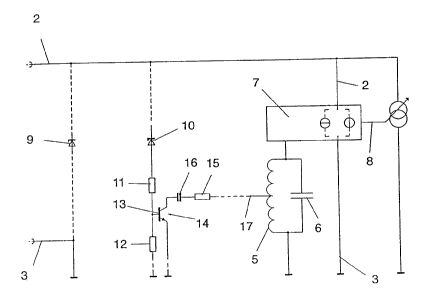
A principal circuit arrangement is illustrated in fig. 2.
Fig. 2 shows a resonant circuit coil identified by the number 5, whereby the
LC member
characteristic for the resonant circuit has a condenser 6. A proximity of a
measurement
object to the coil 5 leads to a mechanical attenuation, whereby the oscillator
is
schematically identified by the number 7, and depending on the resonant
amplitude,
supplies a corresponding constant current that is supplied by means of the
signal line 8.
In the measurement operation of this sensor in two-wire circuit, the
oscillator 7 is
supplied by a constant current source, or a constant voltage source,
CA 02400062 2002-08-13
_7_
and therefore shows no substantial changes with a change in the supply
voltage. The
supply voltage is fed via the line 2 and 3, whereby the first decimal. diode 9
is intended,
with which voltage peaks are to be eliminated, which could lead to failures in
the circuit
arrangement. This first decimal diode 9 is laid out for a higher forward
voltage, than the
second decimal diode 10 illustrated in fig. 2.
By increasing the supply voltage from typically 12 to 18 V to 22 V, for
example, current
can now flow across the resistances 11 and 12 forming a voltage separator, at
a
corresponding layout of the decimal diode 10, and the base 13 of the
transistor 14 can be
made conductive in this way so that now current can flow across the resistance
15, the
condenser 16, as well as the collector and the emitter of the transistor 14.
As this
resistance 15 is connected to the line 17 at a disassembled state of the coil
5, an electric
attenuation of the resonant circuit occurs in this case, by which the measured
amplitude is
changed, and additional signals may be gained by means of the line 8.
The constant current source, or the constant voltage source, respectively,
controls an
amplifier that sounds the sensor signal in the form of an active current
signal on the
supply line. This amplifier also has no dependency on the voltage. Energy is
withdrawn
from the resonant circuit by means of tapping of a sensor coil at a switched
in electric
attenuation, whereby this energy loss that physically corresponds to a loss,
which may be
caused by eddy current and re-magnetizing losses at the sensor coil, leads to
a change of
the current readings before and after the defined attenuation, which may then
be
compared to the respective desired characteristic lines between both points.
Controlled voltage changes simultaneously allow a limited test of the sensor
circuit, as
well as of the cable routing.
CA 02400062 2002-08-13
_g_
A change in the current signal after the increase or decrease of the supply
voltage would
mean that either a defect in the cable routing, or in a circuit component of
the sensor is
present. If the sensor is cyclic tested, the amount of components responsible
for the
undetected failures of the sensor can be substantially reduced. Controlled by
the decimal
diode 10, the transistor 14 is thereby used as a circuit that diverts energy
from the
resonant circuit via the resistance with a defined increase of the supply
voltage. Such a
circuit operation for the cyclic scanning of the electric attenuated
measurement readings
can be caused by the temporary increase of the sensor supply voltage. Any
undesired
parasitic resistances would lead to a current increase with the increased
supply voltage,
whereby such errors also become recognizable by the circuit arrangement.
The characteristic line courses are illustrated in fig. 3 and fig. 4.
Fig. 3 shows the first characteristic line 18, which mirrors the course of the
current
consumption in dependency of the mechanical attenuation. In a defective
sensor, or one
that is becoming defective, this current measurement reading decreasing
according the
curve 19, whereby it is simultaneously clear that the change in measurement
readings at
the maximum distance, i.e. in the mechanical non-attenuated condition of the
sensor,
becomes significantly low, and does not become noticeably measurable until the
distance
is decreased, and therefore the mechanical attenuation is increased. A
defective sensor,
the characteristic line course of which, for instance, corresponds to the
curve 19, would
then, however, if it is not recognized that the sensor is defective in a
timely fashion, lead
to the wrong proximity values, as the minimum current with the assembly of a
tongue at
point 20 would already be achieved at point 21 with an intact sensor on the
characteristic
line of the defective sensor, which would therefore result in too large of a
distance in the
corresponding evaluation.
CA 02400062 2002-08-13
-9-
The curve line 22 corresponds to an intact sensor with simultaneous additional
electric
attenuation. It has now been shown that that significant differences occur in
a defective
sensor with switched in electric attenuation corresponding to the curve course
of the
curve 23, even with the disassembly of the tongue, which point to a defective
sensor. The
difference, as measured for the disassembly of the tongue between the
conditions without
and with electric attenuation, corresponds here to the difference of the
measurement
currents b, while in the case of a defective sensor, this difference is
significantly higher,
and corresponds to c.
If now, as illustrated in fig. 4, the electric attenuation is cyclically
switched in, a signal
course occurs for each intact sensor, which corresponds to the curve course 24
in fig. 4,
whereby clearly the decrease of the current consumption respectively
registered with the
circuitry of the transistor is evident. This decrease is indicated by the
respective partial
areas 25, 26, 27 28, 29, and 30, whereby this difference is simultaneously
differs for the
different mechanical attenuations of the sensor.
If a defective sensor is present, then the difference at the stated points of
the curve course
increases, whereby the additionally measured current difference is indicated
by the curve
course at the points 31, 32, 33, 34, 35, and 36. In this case, however, the
difference is no
longer based on the original characteristic line 24, but instead is
recognizable as a
measurement reading exactly based on the characteristic line 19 of the
defective sensor.
From all of these signal difference, the required prognosis can be made, and
particularly
the failure probability of inductive proximity sensors for the monitoring of
the position of
movable switch rails or rail components can be quantified.