Language selection

Search

Patent 2400225 Summary

Third-party information liability

Some of the information on this Web page has been provided by external sources. The Government of Canada is not responsible for the accuracy, reliability or currency of the information supplied by external sources. Users wishing to rely upon this information should consult directly with the source of the information. Content provided by external sources is not subject to official languages, privacy and accessibility requirements.

Claims and Abstract availability

Any discrepancies in the text and image of the Claims and Abstract are due to differing posting times. Text of the Claims and Abstract are posted:

  • At the time the application is open to public inspection;
  • At the time of issue of the patent (grant).
(12) Patent Application: (11) CA 2400225
(54) English Title: CHAIR BASE
(54) French Title: PIED DE SIEGE
Status: Deemed Abandoned and Beyond the Period of Reinstatement - Pending Response to Notice of Disregarded Communication
Bibliographic Data
(51) International Patent Classification (IPC):
  • A47C 7/00 (2006.01)
(72) Inventors :
  • DEISIG, WOLFGANG (Germany)
(73) Owners :
  • TK CANADA LIMITED
(71) Applicants :
  • TK CANADA LIMITED (Canada)
(74) Agent: SMART & BIGGAR LP
(74) Associate agent:
(45) Issued:
(86) PCT Filing Date: 2001-02-16
(87) Open to Public Inspection: 2001-08-23
Examination requested: 2005-01-18
Availability of licence: N/A
Dedicated to the Public: N/A
(25) Language of filing: English

Patent Cooperation Treaty (PCT): Yes
(86) PCT Filing Number: PCT/CA2001/000190
(87) International Publication Number: WO 2001060206
(85) National Entry: 2002-08-14

(30) Application Priority Data:
Application No. Country/Territory Date
200 02 799.9 (Germany) 2000-02-16

Abstracts

English Abstract


An anti-tipping chair base has a central support member (2) with a generally
upright axis, and a plurality of arms (3) that extend generally radially
outwardly from the axis and each of which is provided with a caster (4). An
outer end portion (3A) of the arm has a shape that curves downwardly around
the caster to an end edge (3B) outwardly of the caster. As seen in plan, the
outer end portion of the arm has side edges (3C) that diverge in a direction
towards the end edge and between which the end edge extends generally normal
to the radial direction of the arm. The end portions (3A) of the arm comprise
support elements that contact a surface on which the base is disposed in the
event that the base tips in use.


French Abstract

L'invention concerne un pied de siège anti-basculement comportant un support central dont l'axe est en règle générale vertical et une pluralité de bras qui, en règle générale, s'étendent radialement vers l'extérieur à partir de l'axe, chacun d'eux étant doté d'une roulette. L'extrémité extérieure desdits bras a une forme incurvée vers le bas entourant la roulette et se terminant par un bord terminal extérieur à la roulette. Comme l'indique le schéma, l'extrémité extérieure d'un bras est dotée de bords latéraux divergeants, orientés vers le bord terminal et entre lesquels ce dernier s'étend, en règle générale, perpendiculairement au rayon du bras. Les parties terminales des bras comportent des éléments supports qui s'appuient sur la surface où le pied de siège est posé lorsque celui-ci bascule.

Claims

Note: Claims are shown in the official language in which they were submitted.

-5-
I CLAIM:
1. An anti-tipping chair base comprising a central support
member having a generally upright axis, and a plurality of arms that extend
generally radially outwardly from said axis and each of which is provided
with a caster adjacent an outer end portion of the arm, wherein said outer
end portion of each arm has a shape that curves downwardly around the
caster to an end edge outwardly of the caster and that is defined as seen in
plan by side edges that diverge in a direction towards said end edge and
between which said end edge extends generally normal to the radial
direction of the arm, said end portions of the respective arms comprising
support elements for contact with a surface on which the base is disposed
in the event that said base tips in use.
2. A chair base as claimed in claim 1, wherein the outer end
portion of each arm comprising a said supporting element is fork-shaped,
comprising a pair of divergent limbs and a transverse bar connecting outer
ends of said limbs.
3. A chair base according to claim 2, wherein the connecting bar
is arcuate in a direction outwardly from the axis of the central support
member.
4. A base according to any one of the preceding claims, wherein
the outer end portion of each arm comprising said support element is a
component separate from the remainder of the arm.

Description

Note: Descriptions are shown in the official language in which they were submitted.


CA 02400225 2002-08-14
WO 01/60206 PCT/CA01/00190
-1-
Title: CHAIR BASE
FIELD OF THE INVENTION
The present invention concerns a so-called "anti-tipping" chair
base, for example for an office chair.
BACKGROUND OF THE INVENTION
DE-GM 73 44 658 discloses a chair base having a plurality of
arms which extend radially outwardly from a central support column, and
each of which has a caster at its outer end. Each caster is surrounded by a
bell whose outer contour has one or several lower edges that function as
support elements if the chair tips. A disadvantage here is that the respective
lower edges of the supporting elements, in the normal position of the chair
base, are low to the ground and support in an undefined position when the
chair tips.
SUMMARY OF THE INVENTION
An object of the invention is to improve the effectiveness of the
chair base in the tipped position.
According to the invention, there is provided an anti-tipping
chair base comprising a central support element having a generally upright
axis and a plurality of arms that extends generally radially outwardly from
the
axis and each of which is provided with a caster adjacent an outer end
portion of the arm. The outer end portion of each arm has a shape that
curves downwardly around the caster to an end edge outwardly of the caster
and that is defined as seen in plan by side edges that diverge in a direction
towards the end edge and between which the end edge extends generally
normal to the radial direction of the arm. The end portions of the respective
arms comprise support elements for contact with a surface on which the
base is disposed in the event that the base tips in use.
One embodiment of the invention envisions a support element
that is fork-shaped with the two fork ends connected by an essentially
horizontal connecting bar. In this way, each support element forms with an
adjacent arm, a defined resting point in any given tipped position of the

CA 02400225 2002-08-14
WO 01/60206 PCT/CA01/00190
-2-
chair, which means that the chair is securely supported on the floor in any
tipped position of the chair, even when the casters are turned inwards.
The connecting bar may be arcuate in a direction outwardly
from the centre of the base. This protects the user of the chair against
accidentally trapping a foot between the two fork ends.
BRIEF DESCRIPTION OF THE DRAWINGS
In order that the invention may be more clearly understood,
reference will now be made to the accompanying drawings which illustrate
a particular preferred embodiment of the invention by way of example, and in
which:
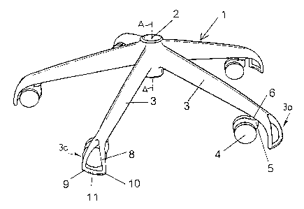
Fig. 1 is a perspective view from above of a five-arm chair base
in accordance with the invention;
Fig. 2 is a plan view corresponding to Fig. 1;
Fig. 3 is a plan view of an outer end portion of one of the arms
with the caster turned inwardly;
Fig. 4 is a side elevational view corresponding to Fig. 3;
Fig. 5 is a front elevational view corresponding to Fig. 3;
Fig. 6 is a front elevational view of the base showing one
caster turned inwardly and one caster turned outwardly; and,
Fig. 7 is view similar to Fig. 6, showing the base in a tipped
position.
DESCRIPTION OF PREFERRED EMBODIMENT
The anti-tipping chair base in accordance with the invention
includes a central support element 2 having a generally upright axis A-A and
a plurality of arms 3 that extend generally radially outwardly from axis A-A.
Each arm is provided with a caster 4 adjacent an outer end portion 3a of the
arm.
As best seen in Figs. 4, 6 and 7, the outer end portion 3a of
each arm has a shape that curves downwardly around the caster to an end
edge 3b outwardly of the caster. The shape of the outer end portion as seen
in plan is defined by side edges 3c that diverge in a direction towards the
end edge 3b and between which the end edge 3b extends generally normal

CA 02400225 2002-08-14
WO 01/60206 PCT/CA01/00190
-3-
to the radial direction of the arm. The end portions 3a of the respective arms
accordingly provide support elements for contact with a surface on which the
base is disposed in the event that the base tips in use.
As will be described in more detail below, the drawings show
an embodiment of the invention in which the outer end portion 3a
(supporting element) of each arm is generally fork-shaped with a bar that
extends between the outer ends of the limbs of the fork. However, this fork
shape is not essential to the invention. In another embodiment, the outer
end portion 3a of each arm could be of plain (imperforate) generally
triangular shape.
Referring now more specifically to the drawings, the central
support element 2 of the base 1 is designed to receive a support column for
the seat and back assembly of the chair (not shown); typically, element 2 will
be of hollow cylindrical form.
The chair base 1, element 2 and arms 3 can be made of metal
or plastic and may be made in one piece. Casters 4 have conventional
double-roll wheels which turn on respective horizontal axes B-B (Fig. 2).
Each caster also has a pin 5 which is set on a vertical axis 6 of the
respective arm 3, so that the caster can turn about axis 6.
The supporting element (3a) of each arm 3 may be made in
one piece with the arm 3 or separately and may be made of metal or plastic.
In this embodiment, the supporting element 3a is fork-shaped and the two
fork limbs diverge at about 60° to form two horizontally spaced support
points 9, 10 (Figs. 3, 4 and 5). Points 9, 10 may be located at a distance d
(Fig. 4) of 3 to 10 mm from the floor when the center axis A-A of the chair
base 1 is in a vertical position. The support points 9, 10 of two
neighbouring, opposed fork ends 8 of adjacent arms 3 form a virtual
standing surface that provides the required stability of the base of the chair
(in particular an office chair) in the tilted position of the chair base 1.
The
two forked ends 8 are connected by a horizontal connecting bar 11 that is
outwardly arcuate in relation to the centre axis A-A of the chair base 1.
A chair base 1 according to the invention having fork-shaped

CA 02400225 2002-08-14
WO 01/60206 PCT/CA01/00190
-4-
support elements 3a meets the German Industrial Standard for the stability
of rotatable office chairs (DIN 445/52). The measure of stability is
determined as the smallest distance between a line connecting two
neighbouring support points 9, 10 to the rotary axis A-A of the chair.
Support points 9, 10 are those points of movable or rigid parts
of the chair that are always in contact with the floor. When using casters the
caster position which is least favourable to stability must be the starting
point. Apart from the measure of stability required here, stability is
increased by the fork-shaped supporting elements 3a of the chair base 1,
because the bearing structure of each arm is extended somewhat past the
relevant caster 4. In this case, the fork ends 8 of the supporting elements 7
are spaced 3 to 10 mm above the floor. In an extreme seated position with
the casters 4 (Fig. 7) turned inwardly towards the central axis A-A of the
base
1, the base 1 and therefore the office chair are prevented from tipping.
The support elements 3a can be made of the same material
as the arm 3 and may be formed in one piece from plastic, aluminum or
steel. The support elements 3a can also be separate components made
from aluminum, steel or plastic and attached to the main part of the arm 3
on which the caster 4 is mounted.
It will of course be appreciated that the preceding description
relates to a particular preferred embodiment of the invention only and that
many modifications are possible within the broad scope of the invention.
Some of those modifications have been indicated previously and others will
be apparent to a person skilled in the art. Clearly, the overall form of the
base shown in the drawings is an example only. The anti-tipping feature of
the invention may be applied to bases of other configurations (different
numbers and shapes of arms and different types of casters).

Representative Drawing
A single figure which represents the drawing illustrating the invention.
Administrative Status

2024-08-01:As part of the Next Generation Patents (NGP) transition, the Canadian Patents Database (CPD) now contains a more detailed Event History, which replicates the Event Log of our new back-office solution.

Please note that "Inactive:" events refers to events no longer in use in our new back-office solution.

For a clearer understanding of the status of the application/patent presented on this page, the site Disclaimer , as well as the definitions for Patent , Event History , Maintenance Fee  and Payment History  should be consulted.

Event History

Description Date
Application Not Reinstated by Deadline 2007-02-16
Time Limit for Reversal Expired 2007-02-16
Deemed Abandoned - Failure to Respond to Maintenance Fee Notice 2006-02-16
Amendment Received - Voluntary Amendment 2005-05-24
Letter Sent 2005-01-25
Request for Examination Received 2005-01-18
All Requirements for Examination Determined Compliant 2005-01-18
Request for Examination Requirements Determined Compliant 2005-01-18
Inactive: Cover page published 2002-12-05
Letter Sent 2002-12-02
Inactive: Notice - National entry - No RFE 2002-12-02
Application Received - PCT 2002-10-07
National Entry Requirements Determined Compliant 2002-08-14
Application Published (Open to Public Inspection) 2001-08-23

Abandonment History

Abandonment Date Reason Reinstatement Date
2006-02-16

Maintenance Fee

The last payment was received on 2005-01-18

Note : If the full payment has not been received on or before the date indicated, a further fee may be required which may be one of the following

  • the reinstatement fee;
  • the late payment fee; or
  • additional fee to reverse deemed expiry.

Patent fees are adjusted on the 1st of January every year. The amounts above are the current amounts if received by December 31 of the current year.
Please refer to the CIPO Patent Fees web page to see all current fee amounts.

Fee History

Fee Type Anniversary Year Due Date Paid Date
Registration of a document 2002-08-14
Basic national fee - standard 2002-08-14
MF (application, 2nd anniv.) - standard 02 2003-02-17 2002-08-14
MF (application, 3rd anniv.) - standard 03 2004-02-16 2003-12-18
MF (application, 4th anniv.) - standard 04 2005-02-16 2005-01-18
Request for examination - standard 2005-01-18
Owners on Record

Note: Records showing the ownership history in alphabetical order.

Current Owners on Record
TK CANADA LIMITED
Past Owners on Record
WOLFGANG DEISIG
Past Owners that do not appear in the "Owners on Record" listing will appear in other documentation within the application.
Documents

To view selected files, please enter reCAPTCHA code :


To view images, click a link in the Document Description column. To download the documents, select one or more checkboxes in the first column and then click the "Download Selected in PDF format (Zip Archive)" or the "Download Selected as Single PDF" button.

List of published and non-published patent-specific documents on the CPD .

If you have any difficulty accessing content, you can call the Client Service Centre at 1-866-997-1936 or send them an e-mail at CIPO Client Service Centre.


Document
Description 
Date
(yyyy-mm-dd) 
Number of pages   Size of Image (KB) 
Representative drawing 2002-12-03 1 9
Abstract 2002-08-13 2 63
Claims 2002-08-13 1 32
Drawings 2002-08-13 3 60
Description 2002-08-13 4 185
Notice of National Entry 2002-12-01 1 189
Courtesy - Certificate of registration (related document(s)) 2002-12-01 1 106
Acknowledgement of Request for Examination 2005-01-24 1 176
Courtesy - Abandonment Letter (Maintenance Fee) 2006-04-12 1 177
PCT 2002-08-13 4 111
PCT 2002-08-14 2 61
Fees 2003-12-17 1 34
Fees 2005-01-17 1 27