Note: Descriptions are shown in the official language in which they were submitted.
CA 02400349 2002-08-23
WO 01/68169 PCT/US01/02262
-1-
DRY POWDER INHALER DEVICES, MULTI-DOSE DRY POWDER DRUG
PACKAGES, CONTROL SYSTEMS, AND ASSOCIATED METHODS
Field of the Invention
The present invention relates generally to drug delivery devices and
more particularly to dose-regulated dry powder inhalers.
Background of the Invention
Delivery of drugs as inhaled aerosols is well known. Indeed,
asthma and other respiratory ailments have long been treated with inhaled
aerosols. Presently, there is also an interest in expanding this
administration
concept to locally acting agents such as antimicrobials, protease inhibitors,
and nucleic acids/oligios as well as systemic agents such as peptides like
leuprolide and proteins such as insulin. For example, inhaler based delivery
of antimicrobial agents such as antitubercular compounds, proteins such as
insulin for diabetes therapy or other insulin-resistant related disorders,
peptides such as leuprolide acetate for treatment of prostate cancer and
endometriosis and nucleic acids or ogligonucleotides for cystic fibrosis gene
therapy. See e.g. Wolff et al., Generation of Aerosolized Drugs, J. Aerosol:
Med. pp. 89-106 (1994).
Generally described, there are three types of inhaler devices used to
administer and deliver drug therapies via aerosol-based inhalation. The
most common type used (typically associated with asthma treatments) is the
pressurized metered dose inhaler (pMDI). This type of inhaler uses an
ozone-depleting CFC propellant such as freon, which is banned for most
commercial applications, but which presently has medical exemption.
Alternatives to the pMDI devices are an important area of aerosol delivery
research primarily because the number of non-CFC propellants is limited
and reformulation is difficult.
Inhalant drug aerosols can also be generated by the use of
nebulizers. Until recently, use of these nebulizer-type devices was typically
SUBSTITUTE SHEET (RULE 26)
CA 02400349 2002-08-23
WO 01/68169 PCT/USO1/02262
-2-
limited to clinical sites and the home due primarily to their power
requirements. In operation, nebulizers deliver droplets in a size range that
enables the drug to reach the periphery of the lung through the air passage
of a patient. However, because the droplets are very small (such as on the
order of less than about 2.0 pm), a relatively long treatment time is usually
required to deliver a clinically significant dose.
A third type of inhaler is a dry powder inhaler (DPI), which represents
a promising alternative to pMDI devices for delivering drug aerosols.
Typically, the DPIs are configures to deliver a powdered drug or drug
mixture which includes an excipient and/or other ingredients.
Conventionally, many DPIs have operated passively, relying on the
inspiratory effort of the patient to dispense the drug provided by the powder.
Unfortunately, this passive operation can lead to poor dosing uniformity
since inspiratory capabilities can vary from patient to patient (and sometimes
even use to use by the same patient, particularly if the patient is undergoing
an asthmatic attack or respiratory-type ailment which tends to close the
airway).
Generally described, known single and multiple dose dry powder DPI
devices use either individual pre-measured doses, such as capsules
containing the drug, which can be inserted into the device prior to
dispensing. Alternatively, DPI devices can operate based on bulk powder
reservoirs which are configured to administer successive quantities of the
drug to the patient via a dispensing chamber which dispenses the proper
dose. See generally Prime et al., Review of Dry Powder Inhalers, 26 Adv.
Drug Delivery Rev., pp. 51-58 (1997); and Hickey et al., A new millennium
for inhaler technology, 21 Pharm. Tech., n. 6, pp. 116-125 (1997).
In operation, particularly of DPI devices, it is desired that a uniform
dispersion amount and desired physical form (such as a particulate size) of
the dry powder be dispersed into a patient's airway and directed to the
desired deposit site. If the patient is unable to provide sufficient
respiratory
effort, the extent of drug penetration, especially to the lower portion of the
SUBSTITUTE SHEET (RULE 26)
CA 02400349 2002-08-23
WO 01/68169 PCT/USO1/02262
-3-
airway, may be impeded. This may result in premature deposit of the
powder in the patient's mouth or throat.
Further, a number of obstacles can desirably affect the performance
of the DPI. For example, the small size of the inhalable particles in the dry
powder drug mixture can subject them to forces of agglomeration and/or
cohesion (i.e., certain types of dry powders are susceptible to
agglomeration, which is typically caused by particles of the drug adhering
together), which disadvantageously results in poor flow and non-uniform
dispersion. In addition, as noted above, many dry powder formulations
employ larger excipient particles to promote flow properties of the drug.
However, separation of the drug from the excipient as well as the presence
of agglomeration can require additional inspiratory effort, which again, can
impact the stable dispersion of the powder within the airstream of the patient
such that it reaches its preferred deposit/destination site and reduces the
amount of the drug which is prematurely deposited elsewhere.
Further, many dry powder inhalers can retain a significant amount of
the drug within the device, which can be especially problematic over time.
Typically, this problem requires that the device be cleansed to assure that it
is in proper working order. In addition, the hygroscopic nature of many of
these dry powder drugs may also require that the device be cleansed (and
dried) at periodic intervals.
Some inhalation devices have attempted to resolve problems
attendant with conventional passive inhalers. For example, U.S. Patent No.
5,655,523 proposes a dry powder inhalation device which has a
deagglormeration/aerosolization plunger rod or biased hammer and solenoid
and U.S. Patent No. 3,948,264 proposes the use of a battery-powered
solenoid buzzer to vibrate the capsule to effectuate the release of the
powder contained therein. These devices propose to facilitate the release of
the dry powder by the use of energy input independent of patient respiratory
effort. However, there remains a need to provide improved, easy to use,
cost effective, and reliable dry powder inhalers.
SUBSTITUTE SHEET (RULE 26)
CA 02400349 2002-08-23
WO 01/68169 PCT/US01/02262
-4-
Obiects and Summary of the Invention
It is therefore an object of the present invention to provide an
improved dry powder inhaler which can disperse more uniform doses.
It is another object of the present invention to provide a DPI system to
actively facilitate the dispersion and release of dry powder drug formulations
during inhalation which can increase the quantity of fine particle fraction
particles dispersed or emitted from the device over convention DPI systems.
It is another object of the present invention to provide an economic,
disposable blister package configuration with active dispersion elements and
multiple dry powder doses positioned thereon to reduce the cleaning
difficulty and frequency of the inhaler.
It is an additional object of the present invention to provide an
integrated control system for an inhaler that can adjust the operation of the
inhaler based on actively detected or predetermined parameters.
It is yet another object of the present invention to provide control
systems which are configured to analyze predetermined conditions and/or
parameters which can dynamically adjust the operation of the inhaler during
use.
It is a further object of the present invention to provide logic-based
control systems to determine and adjust the operation of devices and/or
apparatus that employ and/or dispense dry powder substances.
These and other objects of the present invention are provided by
methods, systems, and computer program products for administering and
dispensing dry powder based drug formulations via inhalers. Preferably, a
multi-layer active drug package is configured to vibrate or oscillate in
response to the application of an excitation voltage thereto. The multi-layer
drug package is preferably a drug blister package configured to protect the
drug from humidity prior to active dispersion of the dose. The multi-layer
drug blister package employs a thin layer of piezoelectric polymer material
such as polyvinylidene fluoride ("PVDF") film with electrical traces
configured
thereon to apply the electrical excitation voltage differential thereacross at
the desired region of the package and oscillate the drug package about the
SUBSTITUTE SHEET (RULE 26)
CA 02400349 2002-08-23
WO 01/68169 PCTIUSOI/02262
-5-
drug blister region to actively assist and disperse the dry powder dose into
the air stream of a user during the inspiratory use. In addition, the inhaler
can use a fuzzy logic based control system and one or more sensors to
provide active control/feedback and dynamic adjustments to the dispersion
control system based on sensed real-time conditions (such as user air flow
rate, temperature, humidity and the like) and/or predetermined conditions
and parameters corresponding to the drug being delivered or the systemic
target of same.
As will be appreciated by those of skill in the art, the present invention
may be provided as one or combinations of devices, methods, systems, or
computer program products.
A first aspect of the present invention is directed to a multi-dose dry
powder blister package. The package includes a platform body comprising a
piezoelectric material layer with opposing first and second major surfaces.
The first major surface of the piezoelectric material layer includes a first
plurality of spatially separated metal traces disposed thereon. The first
plurality of metal traces are configured to include a transmission line and an
active pad region. The second major surface of the piezoelectric material
includes a second plurality of spatially separated metal traces disposed
thereon. The second plurality of metal traces are configured to include a
transmission line and an active pad region. Each of the second plurality of
traces are positioned such that it is aligned with a corresponding one of the
first plurality of separated metal traces to define a corresponding pair of
opposing metal traces with an individually operable electrical excitation path
therebetween. The package also includes a plurality of depressed wells
formed in the platform body. The wells are configured to hold a
predetermined quantity of dry powder pharmaceutical drug therein. Each of
the depressed wells is positioned on the platform body to substantially
overlie a respective active pad region of one pair of corresponding first and
second metal traces.
In a preferred embodiment, in operation, in response to application of
an excitation voltage differential to a selected one of the individually
SUBSTITUTE SHEET (RULE 26)
CA 02400349 2002-08-23
WO 01/68169 PCT/US01/02262
-6-
operable electrical paths, the piezoelectric material layer deforms at the
active pad region to thereby actively disperse the dry powder pharmaceutical
drug from the depressed well. The package can include one or more of a
sealed releasable polymer cap positioned to overlie the plurality of
depressed wells and a non-reactive barrier positioned in each of the
depressed wells to define a dry powder drug contact surface therein.
In a preferred embodiment, the multi-dose dry powder blister package
is configured to be received in a dry powder inhaler. The dry powder inhaler
comprises a housing and a control system positioned therein, wherein during
operation, the housing is configured to be in fluid communication with a user
and define a flow exit path therefrom. The control system comprises a
controller configured to engage with a selected one of the individually
operable electrical paths. The control system also includes a battery having
a first voltage output operably associated with the controller and a
transformer for increasing the first voltage to a desired excitation voltage
operably associated with the controller and the selected individually operable
electrical path. The control system also includes an airflow sensor
positioned in the flow exit path, and is preferably positioned upstream of the
depressed well in the flow exit path (the well is intermediate the sensor and
the use). This positioning can reduce the deposition of drug particles on the
sensor. In operation, the controller is configured to adjust the excitation
voltage corresponding to predetermined parameters associated with the
dispersion of the dry powder drug.
In a preferred embodiment, the controller is programmed with a fuzzy
logic system representing at least one of flow characteristics of the dry
powder drug and the inspiratory capability of the user such that the
excitation voltage transmitted to the selected electrical path is responsive
to
the results of the fuzzy logic system.
Similar to the first aspect of the invention described above, another
aspect of the invention is directed to a disposable multi-dose dry powder
package, with at least one integrated active element formed thereon. The
dry powder package comprises a piezoelectric polymer firm having a
SUBSTITUTE SHEET (RULE 26)
CA 02400349 2002-08-23
WO 01/68169 PCTIUSOI/02262
-7-
substantially planar profile and an upper and lower surface. A first metal
trace pattern is positioned onto the upper surface. The first metal trace
pattern has a plurality of first pad regions and a plurality of first linear
transmission lines. Each first pad region is connected to a respective one of
the first linear transmission lines. A second metal trace pattern is
positioned
onto the lower surface. The second metal trace pattern has a plurality of
second pad regions and a plurality of second linear transmission lines. Each
second pad region is connected to a respective one second linear
transmission line. The first and second metal trace patterns are aligned
across the piezoelectric polymer material layer. The package also includes
a plurality of individual quantities of dry powder drug positioned to
substantially overlie each of the first pad regions on said upper surface. A
sealant layer is positioned to overlay each of the unitized quantities of the
dry powder drug to secure it in the disposable dry powder package.
In one embodiment, the piezoelectric polymer film is a thin film PVDF,
and a backing material layer can be positioned to overlie a substantial
portion of the lower surface of the PVDF.
Another aspect of the present invention is a method of dispersing an
inhalable quantity of a dry powder pharmaceutical drug into a patient's
airstream. The method includes the steps of positioning and holding a dry
powder inhaler such that tit is in fluid communication with a user and ready
to direct a quantity of dry powder pharmaceutical drug into the air stream of
a user during inhalation, wherein the package holds at least one unitized
quantity of dry powder pharmaceutical drug in a receptacle portion of
thereon, the receptacle portion including a piezoelectric polymer material
layer. The method also includes the steps of repeatedly applying a voltage
differential across the piezoelectric polymer film in the region of the
receptacle to deform the receptacle and expelling the dry powder drug held
in the receptacle portion of the package such that it is dispersed into the
air
stream of a user during the user's inspiratory inhalation cycle.
Preferably, the deforming step is carried out by flexing the
piezoelectric material in the region of the receptacle portion. The applying
SUBSTITUTE SHEET (RULE 26)
CA 02400349 2002-08-23
WO 01/68169 PCTIUSOI/02262
-8-
step can be carried out by providing a voltage of about 100-200 volts peak to
peak across the piezoelectric layer. The voltage can be applied at various
frequencies such as at a relatively low frequency of between about 3-60Hz
and/or a higher frequency of between about 25kHZ to about 2 MHz.
The method can also include the step of measuring the inspiratory air
flow rate of a user and controlling the voltage applied during said applying
step responsive to the user's inspiratory flow rate obtained from said
measuring step. The method can also include the step of forming the exit
flow channel to provide or increase the turbulence of the airflow,
particularly
proximate the well.
The user's air flow rate can be established proximate to active
dispensing of the dry powder drug (near the start of the inhalation cycle), it
can be established based on an average air flow rate measured during prior
uses, or on air flow rates obtained dynamically through the inhalation cycle.
The method can also include the step of defining a fuzzy logic
function representing at least one predetermined condition. The at least one
condition is associated with at least one of the configurations of the dry
powder inhaler, the inspiratory ability of a user, flowability of the
formulation
of the dry powder pharmaceutical drug being administered, and respirable
particle fraction data associated with the dry powder formulation. The
method can also include the steps of determining the degree of membership
for the at least one condition to the defined fuzzy logic function and
adjusting
the excitation voltage applied during the applying step based on the defining
and determining steps.
Preferably, the fuzzy logic function controls the voltage output
delivered during the applying step. The method can also include the steps
of programming the dry powder inhaler with a computer readable program
code which identifies a range of operational excitation output pulses having
associated frequencies, amplitudes, and signal patterns associated
therewith, and programming the dry powder inhaler with computer readable
code which defines operational excitation output pulses suitable for
predetermined types of dry powder drug formulations. The predefined
SUBSTITUTE SHEET (RULE 26)
CA 02400349 2002-08-23
WO 01/68169 PCTIUSOI/02262
-9-
ranges can speed up the selection or analysis process of the controller by
limiting the range of operation of the device by narrowing the excitation
pulses selectable based on the identified dry powder drug being dispensed
and/or for particular types of systemic delivery targets.
An additional aspect of the present invention, similar to the method
described above, is directed to a method of facilitating the dispersion of a
dose of a dry powder drug into an inhalation delivery path. The method
includes the steps of positioning a quantity of dry powder drug in a package
having a piezoelectric polymer material layer, the piezoelectric polymer
material layer having a plurality of receptacle regions configured and sized
to
hold the dry powder drug (in unitized quantities) proximate thereto, the
piezoelectric polymer material layer configured with a plurality of
selectively
excitable regions corresponding to the plurality of receptacle regions. The
method also includes the step of selectively applying an excitation signal to
at least one of the selectively excitable regions to rapidly flex the
piezoelectric polymer material layer thereat to deform at least one receptacle
region to thereby facilitate the dispersal of the dry powder drug into the
inhalation delivery path.
Yet another aspect of the present invention is directed to a method of
controlling a dry powder inhaler. The method comprises the steps of
providing a dry powder inhaler having an active delivery system and an air
flow sensor positioned in the exit flow path, measuring the air flow rate
associated with the inspiratory efforts of a user using dry powder inhaler
proximate to the desired administration of the dry powder drug, and
adjusting the energy directed to the active delivery system responsive to the
measuring step to thereby facilitate increased dose dispersion uniformly
corresponding to the capabilities of a use.
An additional aspect of the present invention is a method of
controlling the active delivery of a dry powder drug in an inhaler configured
with an active energy assisted drug dispersion system. The method
comprises the steps of establishing a priori a flowability characterization of
a
plurality of dry powder drug formulations. The airflow rate of a user using
SUBSTITUTE SHEET (RULE 26)
CA 02400349 2002-08-23
WO 01/68169 PCT/US01/02262
-10-
the dry powder inhaler is measured. A degree of membership of the
flowability of the drug to be dispersed is determined utilizing a first fuzzy
logic function. A degree of membership of the measured airflow rate of the
user with a second fuzzy logic function is determined. The excitation signal
directed to the active energy system of the inhaler is controlled based on the
determined degrees of membership.
Another aspect of the present invention is directed to a method of
fabricating a disposable multi-dose dry powder package which has at least
one (and preferably a plurality of individually activatable elements)
integrated
active element formed thereon. The method comprises the steps of forming
a package with at least one piezoelectric polymer film layer into a desired
geometric shape with an upper and lower surface, dispensing a quantity of
dry powder drug to substantially overlie a plurality of spatially separate
selected upper surface regions of the piezoelectric polymer film layer, and
sealing the dispensed dry powder drug to secure it against the dry powder
package.
The method can also include the steps of forming a first metal trace
pattern on the upper surface, the first metal trace pattern having a plurality
of
pad regions, and a plurality of linear transmission lines, a respective one
connected to each of said pad regions; and forming a second metal trace
pattern onto the lower surface, the second metal trace pattern having a
plurality of pad regions, and a plurality of linear transmission lines, a
respective one connected to each of said pad regions.
In addition, the method can include forming two piezoelectric polymer
film layers, the layers separated by an intermediately positioned pliable
core,
all of which are concurrently deformable by the application of voltage
thereacross.
The present invention can also employ a baffle or irregular shaped
walls in the entrainment tube (exit flow channel) of the inhaler to facilitate
turbulent air flow to increase the fraction of the powder emitted or dispersed
from the device to the user.
SUBSTITUTE SHEET (RULE 26)
CA 02400349 2002-08-23
WO 01/68169 PCT/USO1/02262
-11-
Yet an additional aspect of the present invention is a computer
program product for directing the operation of a dry powder inhaler to
actively facilitate the dispersion of a dry powder drug into the exit flow
path
of the inhaler and into the inhalation flow path of the user. The computer
program product comprises a computer readable storage medium having
computer readable program code embodied in the medium, the computer-
readable program code comprising computer readable program code which
controls an excitation pulse transmitted to an active delivery mechanism in a
dry powder drug inhaler configured with an active energy assisted drug
dispersion system. The computer readable program code also comprises
computer readable program code which defines a fuzzy logic analysis model
to control the amount of energy delivered to the active energy system and
computer readable code which determines the degree of membership of a
dry powder drug to be administered to a first fuzzy logic function associated
with the flowability of the dry powder drug. The computer readable program
code also includes computer readable code which adjusts at least one of the
type, frequency, or size of the excitation signal directed to the active
energy
system of the inhaler based, at least partially, on the determined degree of
membership to the first fuzzy logic function.
In a preferred embodiment, the computer program product also
includes computer readable program code which measures the airflow rate
of a user's inspiratory efforts proximate to active dispersion of the dry
powder drug into the exit flow path of the inhaler, and also includes
computer readable program code which defines the fuzzy logic analysis
model to adjust the excitation signal delivered to the active energy system
includes computer readable code means for analyzing the user's measured
airflow rate.
The computer program product can also include computer readable
program code which considers one or more of the type of excipient used in
the dry powder formulation, the cohesiveness of the dry powder drug, the
geometry of the inhaler, and the systemic delivery target in determining the
excitation pulse to be transmitted.
SUBSTITUTE SHEET (RULE 26)
CA 02400349 2002-08-23
WO 01/68169 PCT/US01/02262
-12-
Advantageously, the present invention may provide more reliable and
uniform inspiratory delivery of dry powder drug treatments with improved
operational characteristics. The DPI, the PVDF blister package, and the
fuzzy logic control system of the instant invention can provide one or more of
the following advantages over conventional DPIs: reproducible dosing,
emission of a high percentage of particles in a respirable size range,
reduced opportunity for accidental multiple dosing, ease of operation,
protection of the drug powder mixture from humidity, and reduced cleansing
requirements.
Brief Description of the Drawings
Figure 1 is a perspective view of a DPI according to the present
invention.
Figure 2 is a top view of a dry powder blister package that is
insertable into the DPI of Figure 1according to the present invention.
Figure 3A is a partial section view taken across line 3A-3A in Figure
2.
Figure 3B is a schematic diagram of an individually selectable
electrical excitation path configured on a dry powder blister package with a
single piezoelectric substrate layer according to the present invention.
Figure 3C is a schematic diagram of an alternate embodiment of an
individually selectable electric excitation path on a dry powder drug package
with multiple piezoelectric substrate layers according to the present
invention.
Figure 3D is a schematic diagram of yet another embodiment of an
individually selectable electrical excitation path drug package with multiple
piezoelectric substrate layers according to the present invention.
Figure 4 is a perspective view of an alternate embodiment of a DPI
according to the present invention.
Figures 5A-5C are top views of alternate embodiments of linear
platform multi-dose blister packages according to the present invention.
SUBSTITUTE SHEET (RULE 26)
CA 02400349 2002-08-23
WO 01/68169 PCT/US01/02262
-13-
Figures 6A and 6B are top views of alternate embodiments of
circular platform blister packages according to the present invention.
Figure 7A and 7B are side perspective views of endless linear
platform blister packages according to additional embodiments of the
present invention.
Figures 8A, 8B, and 8C are cutaway views of alternative DPI
embodiments configured to receive endlessly configured blister packages
such as those shown in Figures 7A and 7B therein.
Figure 9 is a graph illustrating an exemplary excitation signal having
adjustable frequency and/or amplitude according to the present invention.
Figures IOA-IOC are perspective views of alternate embodiments of
DPI inhalers configured to enclose a blister package such as those shown in
Figures 2, 6A, and 6B therein.
Figure 11A is a side cutaway view of a DPI illustrating an integrated
control system according to the present invention.
Figure 11B is a side cutaway view of the DPI shown in Figure 11A
with the blister package raised to be positioned in the inhaler airstream exit
passage so that the dry powder drug is actively dispersed into the inspiratory
air path and directed out of the inhaler.
Figure 11 C is a top view of an alternate embodiment of a circular
platform blister package according to the present invention showing seals
positioned around the perimeter of the drug wells.
Figure 12 is a block diagram of a control system for a DPI according
to the present invention.
Figure 13 is a block diagram of a method of controlling the dispersion
of a dry powder drug according to the present invention.
Figure 14 is a block diagram of a method for controlling the operation
of a DPI according to the present invention.
Figure 15 is a schematic diagram of a fuzzy inference system for
determining the degree of membership of selected fuzzy membership
functions and adjusting the operation of a DPI according to the present
invention.
SUBSTITUTE SHEET (RULE 26)
CA 02400349 2002-08-23
WO 01/68169 PCTIUSOI/02262
-14-
Figure 16 is a graph of a fuzzy membership function for airflow rate
modeling airflow rate as low, medium, and high according to the present
invention.
Figure 17 is a graph of a fuzzy membership function for powder
flowability modeling powder flowability of the formulation as poor, good, or
otherwise, according to the present invention.
Detailed Description of the Invention
The present invention now will be described more fully hereinafter
with reference to the accompanying drawings, in which preferred
embodiments of the invention are shown. This invention may, however, be
embodied in many different forms and should not be construed as limited to
the embodiments set forth herein; rather, these embodiments are provided
so that this disclosure will be thorough and complete, and will fully convey
the scope of the invention to those skilled in the art. Like numbers refer to
like elements throughout. In the figures, components, layers, or regions may
be exaggerated for clarity.
Generally described, the present invention is directed to dry powder
inhalers with integrated, active energy, patient-assisted dispersal systems
which are configured with control systems that provide adjustable energy
output to the active dispersal element responsive to a user's inspiratory
capabilities and/or the flowability of the dry powder drug being administered.
The inhalers can be used for nasal and/or oral (mouth) respiratory delivery.
Preferably, the inhalable dry powder dose is packaged in a multi-dose dry
powder drug package which includes a piezoelectric polymer substrate
(such as PVDF) that flexes to deform rapidly and provide mechanical
oscillation in an individually selectable signal path on the package. The
signal path directs the signal to the region of the drug receptacle or well to
cause the well to oscillate in cooperation with a user's inspiratory effort,
and,
thus, actively direct the dry powder out of the well and up into the exit flow
path. As a result, the powder is actively dispersed into the exit flow path of
the inhaler during the user's inspiratory activity. The dry powder inhaler can
SUBSTITUTE SHEET (RULE 26)
CA 02400349 2002-08-23
WO 01/68169 PCT/US01/02262
-15-
also employ control systems with fuzzy logic models of the flowability of
particular drug formulations (which may also be able to compensate or allow
for the particular type of excipient or other additive used) and systems which
can adjust for the real-time measured inspiratory effort's of the user.
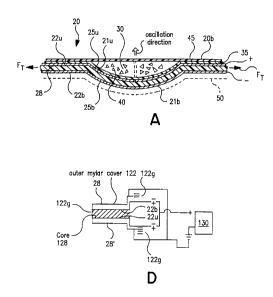
Referring now to Figure 1, one embodiment of a DPI 10 configured to
receive and orally dispense the inhalable dry powder from a multi-dose dry
powder drug package 20 is illustrated. Examples of suitable dry powder
drug packages 20 are also shown in Figures 2 and 3A. As shown, the
multi-dose dry powder drug package 20 includes a platform body 20b with
integrated active elements formed by corresponding upper and lower metal
trace patterns 22u, 22b, which are disposed on a piezoelectric substrate
material layer 28. The platform body 20b includes a first metal trace pattern
22u on the upper surface 21 u of the platform body 20b. As shown, the first
metal trace pattern 22u includes a plurality of spaced-apart pads 25u and a
corresponding transmission line 26u connected to and extending away from
each of the active pads 25u. The bottom of the platform body 21b includes
a second metal trace pattern 22b (Figure 3A). Preferably, the second metal
trace pattern 22b is substantially the same as the first 22u and symmetrically
arranged such that the patterns are aligned the first over the second with the
piezoelectric substrate layer 28 in between.
Referring now to Figures 1 and 2, a plurality of unitized or individual
doses of a dry powder formulation mixture 30 are arranged on the platform
body 20b such that each dose resides against and substantially overlies a
respective active contact pad 25u. For clarity, it will be understood that,
according to the present invention, protective films, moisture protective
barriers, drug protective barriers or coatings may also be positioned over the
substrate layer 28, the traces 22u, 22b, or other portions of the platform
body 20b. Preferably, if applied proximate the active oscillation region/wells
40, they are applied so as to be substantially transparent to the operation of
the active elements. Preferably, as shown in Figure 3A, an inert or
nonreactive barrier 35 is disposed over at least the upper pads 25u to
protect the purity and stability of the dry powder drug from potential
SUBSTITUTE SHEET (RULE 26)
CA 02400349 2002-08-23
WO 01/68169 PCT/USO1/02262
-16-
contamination of or interaction with the dry powder drug which contacts and
resides on this surface. In a preferred embodiment, the inert or non-reactive
barrier 35 is a thin polymer cover or coating material which is applied onto
the upper surface of the platform body 20b such that, in operation, it is
substantially concurrently responsive to the deformation of the piezoelectric
substrate layer 28.
Referring again to Figure 3A, it is also preferred that the first and
second metal trace patterns 22u, 22b are each in contact with, and aligned
across, the piezoelectric substrate layer 28. That is, the first metal trace
pattern 22u is oriented on a first major surface of the piezoelectric
substrate
layer 28 such that it substantially overlies the second metal trace pattern
22b
to define pairs of corresponding transmission lines 26u, 26b and active pads
25u, 25b. As schematically represented in Figure 3B, in operation, each
pair of corresponding transmission lines 26u, 26b and active pads 25u, 25b
can provide an individually excitable electrical excitation path 33.
As is also shown in Figure 3A, it is preferred that the platform body
20b is configured so as to provide a plurality of drug holding receptacles or
depressed wells 40. As shown, the wells 40 are configured to hold a dose or
single-sized bolus quantity of a dry powder drug 30. In a preferred
embodiment, the wells 40 are defined by concave contours formed in the
piezoelectric substrate layer 28. It is also preferred that the dry powder
drug
be sealed in the well by a sealant layer 45 such as a polymer cap. When
the multi-layer package is secured together after filling with the desired
drug,
the package is configured such the at the attached platform body layers,
25 including the opposing active pads 25u, 25b, and the nonreactive barrier
35,
(and optionally the backing layer 50) have a conformal concave shape. That
is, each layer substantially follows the shape of the piezoelectric substrate
layer material 28. Stated differently, in operation, each of the layers 35,
25u,
28, 25b move in concert during application of the excitation signal across the
30 piezoelectric substrate layer 28. Other non-circular receptacle
configurations can also be employed such as, but not limited to, oblate or
prolate spheroids.
SUBSTITUTE SHEET (RULE 26)
CA 02400349 2002-08-23
WO 01/68169 PCT/USO1/02262
-17-
As is also shown in Figure 3A, an optional backing layer 50 can also
be applied to the underside of the platform body 20b. Again, it is preferred
that the backing layer 50 be applied such that it is conformal to the
piezoelectric substrate layer 28 and moves in concert therewith during
activation of the selected well 40. This backing layer 50 can help amplify the
oscillation of the receptacle or well 40 caused by the application of the
excitation signal across the piezoelectric substrate layer 28 by providing
amplifying weight opposite the powder surface. Examples of materials
suitable for the backing layer 50 include, but are not limited to,
polyvinylchloride ("PVC").
As shown in Figure 1, the transmission lines 26u extend radially
inward toward the center of the package 20 where the portion of the DPI 10
holding the controller 125 and the power source 150 (see Figure 11A) is
located (preferably at least a 5Vp-p or 9V button type batter). Similarly, the
bottom transmission lines 26b also extend toward the center of the package
20. In this embodiment, the center of the package includes an aperture or
opening 20o formed therein (Figure 2). As shown in Figure 11A, the DPI
10 is configured with top and bottom portions 75u, 751 and the center
opening 20o of the package 20 allows easy electrical connection between
components held in the bottom portion of 751 with those held in the top
portion 75u. Figures 11A and 11B also illustrate that the DPI housing 75
can be configured with or without a lower portion 751.
When assembled to the DPI 10 illustrated in Figure 1, the
transmission line ends adjacent the center opening 20o in the inhaler
chamber 11 are individually electrically activatable by the controller 125 in
the DPI 10 and, thus, define the selected corresponding transmission line
pair 26u5i 26b5 and the associated electrical excitation signal path or
circuit
33. The transmission lines 26ug, 26be connect in the DPI housing 75 at an
electrical junction (schematically illustrated by box 100j) which provides the
signal/ground or +/- connections to the appropriate side (the upper or lower
transmission lines 26u, 26b) of the drug package 10. The junction can be
SUBSTITUTE SHEET (RULE 26)
CA 02400349 2002-08-23
WO 01/68169 PCT/US01/02262
-18-
formed in a number of ways such as by traces disposed onto surfaces, flex
circuits, wiring, and the like.
The control system 100, thus, preferably acts to electrically activate
selected transmission lines 26us, 26bs and the control system 100 can send
the excitation signal to selectively cause the mechanical oscillation at the
associated well 40 region of the package 10. Because only the selected
transmission lines are electrically connected to the energy source, the other
non-selected drug wells 40 remain static (not electrically activated and
electrically isolated from mechanical oscillation). As the next dose in the
sealed well 40 is rotated into the inhalation chamber 11 (which defines the
exit flow path 12 from the DPI 10), a puncturing means (not shown)
positioned proximate the inhalation chamber 11 can remove the sealant to
expose the dry powder drug 30 in the well 40 to allow the drug to be freely
dispersed when the well 40 is oscillated as described above. The rotation is
illustrated in Figure 1 by the letter "R". The direction of rotation can be
either clockwise or counter clockwise.
As noted above, the dry powder formulation mixture can be a single
ingredient or a plurality of ingredients, whether active or inactive. The
inactive ingredients can include additives added to enhance flowability or to
facilitate delivery to the desired systemic target (such as additives to
inhibit
premature deposit in the respiratory system (such as the mouth) during
inhalation). The dry powder drug formulations can include active particulate
sizes which vary. The device may be particularly suitable for dry powder
formulations having particulates which are in the range of about 0.5-50 pm,
and preferably in the range from about 0.5pm - 20.Opm, and more preferably
in the range of about 0.5Nm - 8.Opm. The dry powder formulation can also
include flow-enhancing ingredients, which typically include particulate sizes,
which are larger than the active ingredient particulate sizes. Preferably, the
flow-enhancing ingredients comprise excipients having particulate sizes on
the order of about 50-100 pm. Preferred excipients include lactose and
trehalose. Other types can also be employed such as sugars which are
approved by the United States Food and Drug Administration ("FDA") as
SUBSTITUTE SHEET (RULE 26)
CA 02400349 2002-08-23
WO 01/68169 PCT/US01/02262
-19-
cryoprotectants (e.g., mannitol) or as solubility enhancers (e.g.,
cyclodextrine) or other generally recognized as safe ("GRAS") excipients.
The dry powder treatments can be used to treat asthma, influenza,
and other respiratory ailments. As noted above, there is also an interest in
expanding this administration concept to include the delivery of antimicrobial
agents such as antitubercular compounds, proteins such as insulin for
diabetes therapy or other insulin-resistance related disorders, nucleic acids
or ogligonucleotides for cystic fibrosis gene therapy and peptides such as
leuprolide acetate for treatment of prostate cancer and/or endometriosis.
Typical dose amounts of the unitized dry powder mixture dispersed in the
inhaler will vary depending on the patient size, the systemic target, and the
particular drug. An exemplary dry powder dose amount for an average adult
is about 20mg and for an average adolescent pediatric subject is from about
5-10 mg.
Exemplary dry powder drugs include, but are not limited to, albuterol,
fluficasone, beclamethasone, cromolyn, terbutaline, fenoterol, R-agonists,
and glucocorticoids.
Advantageously, as the active elements are integral to/included as
part of the disposable drug package 20, unlike many conventional active
dispersion systems, cleansing of the active mechanism portion of the inhaler
is no longer required.
Referring again to Figure 3A, the piezoelectric substrate layer 28 is a
piezoelectric polymer material. In a preferred embodiment, the piezoelectric
polymer film is formed from a piezoelectrically active material such as PVDF
(known as KYNAR piezo film or polyvinylidene fluoride) and its copolymers
or polyvinylidene difluoride and its copolymers (such as the PVDF with its
copolymer trifluoroethylene (PVDF-TrFe)).
In a preferred embodiment, the piezoelectric substrate layer 28 is a
thin film PVDF. As used herein, the term "thin film" means that the
piezoelectric substrate layer 28 is configured as a structurally flexible or
pliable layer which is preferably sized to be about 10-200pm thick.
SUBSTITUTE SHEET (RULE 26)
CA 02400349 2002-08-23
WO 01/68169 PCT/US01/02262
-20-
The metal trace patterns 22u, 22b are preferably provided by
applying a conductive pattern onto the outer faces of the piezoelectric
substrate layer 28. For depositing or forming the metal trace patterns 22u,
22b, any metal depositing or layering techniques can be employed such as
electron beam evaporation, thermal evaporation, painting, spraying, dipping,
or sputtering a conductive material or metallic paint and the like or material
over the selected surfaces of the piezoelectric substrate (preferably a PVDF
layer as noted above). Of course, alternative metallic circuits, foils,
surfaces,
or techniques can also be employed, such as attaching a conductive mylar
layer or flex circuit over the desired portion of the outer surface of the
piezoelectric substrate layer 28. It is preferred that, if flex circuits are
used,
that they are configured or attached to the substrate layer 28 so as to be
substantially transparent to the structure of the sensor array to minimize any
potential dampening interference with the substrate layer 28. It is also noted
that while particular conductive patterns are illustrated in the figures, the
present invention is not limited thereto, as alternative conductive patterns
may also be used.
Preferably, the upper and lower surface metal trace patterns 22u, 22b
do not connect on the platform body 20b. For example, the conductive paint
or ink (such as silver or gold) is applied onto the major surfaces of the
platform body 20b such that it does not extend over the perimeter edge
portions 28e of the piezoelectric substrate layer 28, thereby keeping the
metal trace patterns on the top and bottom surfaces 22u, 22b separated with
the piezoelectric substrate layer 28 therebetween. This configuration forms
the electrical excitation path when connected to a control system 100
(Figure 12) to provide the input/excitation signal for creating the electrical
field that activates the deformation of the piezoelectric substrate layer 28
during operation. As such, the electrical path 33 for each pad 25u, 25b
extends via the respective transmission line 26u, 26b to the electrical
terminations operably connected to the controller 125 (Figure 12).
Referring again to Figures 3A and 3B, the excitation circuit
configuration 33 can be such that the upper trace operates with a positive
SUBSTITUTE SHEET (RULE 26)
CA 02400349 2002-08-23
WO 01/68169 PCT/US01/02262
-21-
polarity while the lower trace has a negative polarity or ground, or vice
versa
(thereby providing the electric field/voltage differential to excite the
piezoelectric substrate in the region of the selected well 40). Of course, the
polarities can also be rapidly reversed during application of the excitation
signal (such as + to -, + to -) depending on the type of excitation signal
used.
Figure 4 illustrates an alternative embodiment of a DPI designated
broadly at 10'. As shown, the housing of the DPI 10' is configured to receive
a linearly configured dry powder package 20 therein. Similarly, the
transmission lines 26u thereon extend laterally toward an edge of the
platform body 20e to allow electricai connection with the power source 150
and the controller 125 in the DPI 10'. In this embodiment, instead of rotating
the package 20 such that the next dose of the dry powder drug 30 is moved
into the inhalation chamber 11, the drug package 20 can be translated in a
direction which is perpendicular to the direction of the transmission lines
26u
into position. As above, a serrated edge or other tearing or puncturing
means can be positioned on or proximate the inhalation chamber to expose
the well to allow the dry powder drug to be freely dispersed. Of course, the
sealant layer 45 may also be manually removed.
Figures 5A, 5B, and 5C illustrate exemplary alternate embodiments
of a multi-dose dry powder drug package with active elements. Figure 5A
illustrates that instead of a single well ro single excitation pad used to
dispense a single use dose as describe above, the package 20 can be
configured with two separate pads 25u1, 25u2. As above, the bottom metal
trace patterns are substantially similarly configured and, preferably a
symmetrical image of the first trace pattern. These two separate pads 25u1,
25u2, (with their respective bottom pads 25b1, 25b2) as shown are aligned
along the length direction (shown as the axis marked as "L") of the inhalation
chamber 11. They can also be alternatively configured, such as, being
aligned along the width direction (shown by the axis marked as "W" in
Figure 4), and/or offset a distance about the "L" axis but configured to be
positioned within the inhalation chamber 11 to be dispersed together during
a single inspiratory dispensing activity by the user. That is, each pad 25u1,
SUBSTITUTE SHEET (RULE 26)
CA 02400349 2002-08-23
WO 01/68169 PCT/USO1/02262
-22-
25u2 (and 25b1, 25b2) via their respective transmission lines 26u1, 26u2
(26b1, 26b2), is activated concurrently to disperse their doses into the exit
flow path 12. Because smaller quantities are dispensed from two wells 40 in
the inhalation chamber 11 (dispensing the same overall single held dose),
less energy may be needed and/or a more uniform dispersion may be
achieved (or even holding two ingredients that can be jointly administered
that are separated before use).
Figure 5B illustrates that the transmission lines 26u, 26b can be
alternately located against alternating edges of the platform body 20b.
Figure 5C illustrates that the pads and transmission lines 25u, 26u (and
correspondingly 25b, 26b) can be arranged such that after doses are
dispensed along one side of the package 20, it can be turned, reinserted,
and activated along the other side (providing an increased density drug
dispensing package). Figures 6A and 6B illustrate similar configurations for
the circular package embodiment of the multi-dose package 20. Of course,
although shown in Figures 5A and 6B with two concurrently excitable pads
25u1, 25u2 (25b1, 25b2) configured to be in the inhalation chamber, the
package 20 can also employ greater numbers of pads in different
combinations (such as one or more or combinations of pads that are side by
side, serially aligned, offset, and the like). Similarly, instead of a
plurality of
separately excitable pads connected by transmission lines such as shown in
Figures 5A and 6B, a single longer pad can be used with multiple wells
formed therein (not shown).
Figures 7A and 7B illustrate yet another embodiment of a multi-dose
dry powder drug package 20 with active elements according to the present
invention. As shown the package 20 is an endless loop. Figure 7B
illustrates that the package 20 can also include sealing ridges 129
intermediate each well or upper surface pad 25u. The purpose of the
sealing ridges 129 will be discussed further below.
Figures 8A-8C illustrate exemplary embodiments of a DPI (each
designated at 10) configured to receive endless drug package 20
configurations (such as those shown at Figures 7A and 7B). As shown, the
SUBSTITUTE SHEET (RULE 26)
CA 02400349 2002-08-23
WO 01/68169 PCT/USO1/02262
-23-
DPI 10 is configured to enclose the package 20 therein. As the package 20
rotatably advances (such as via known advancement means) a puncture
means 200 proximate the inhalation chamber 11 and exit flow path 12
punctures the selected well 40. As shown, each embodiment includes an
inhalation chamber 11 which is in fluid communication with the activated
corresponding trace pair 25u, 25b, 26u, 26b. These inhalation chambers 11
can be configured with walls which extend a distance within the enclosure to
reside against the drug package 20, such as at the sealing ridges 129
described above, to seal, at least partially, the inhalation chamber 11 to
require less patient inspiratory effort. Alternatively, the entire enclosure
or
housing can define the inhalation chamber 11 (not shown).
Figures 10A-10C illustrate embodiments of a DPI (each designated
at 10) configured to enclose, and preferably, seal, the circular multi-dose
dry
powder drug package 20 shown in Figures 2, 6A, and 6B. As shown in
Figures 10B and 10C, the DPI body may be formed into whimsical shapes
which may help make pediatric patients more receptive to the use of the
device. Figure 10B illustrates a science fiction-type spaceship design while
Figure 10C illustrates a turtle shell housing design. Other configurations
such as a lady bug shell, baseball mitt and the like may also be suitable. Of
course, other circular or generally circular designs such as sea shells,
wheels, hats, animals and the like can also be employed.
Figures 11A-11B illustrate a partially sealable DPI 10. In this
embodiment, an opening 111 in the lower floor 111f of the inhalation
chamber 11 is configured to receive the drug well 40 of the package 20
therein. A user operable extension member 172 can be used to raise the
package 20 into a sealed position against the lower floor 111f of the
inhalation chamber. A seal 229 can be positioned around the perimeter of
the well 40 on the package as shown in Figure 11C. Similarly, a
corresponding seal Ills can be positioned proximate to the opening of the
inhalation chamber 111. As shown in Figure 11113, when the extension
member 172 pushes a portion of the package 20 into operative positions, the
control system 100 makes electrical contact with the signal traces 25u, 25b,
SUBSTITUTE SHEET (RULE 26)
CA 02400349 2002-08-23
WO 01/68169 PCT/US01/02262
-24-
26u, 26b to activate the dispersion of the powder 30 into the partially sealed
inhalation chamber 11, directing the dry powder formulation out into the exit
flow path 12. It may be desirable to configure the extension member 172
with a center portion which is pliable so that it can substantially conform to
the piezoelectric substrate layer 28 (acting as a backing layer assisting the
oscillation) (not shown). Alternatively, the extension member 172 may be
configured with a central opening corresponding to the active drug region of
the package to allow the well to oscillate without significantly impeding the
movement of the well 40 (also not shown).
As also shown in Figures 11A and 11B, in a preferred embodiment,
the DPI 10 includes an airflow sensor 300 positioned in the inhalation
chamber 11. The airflow sensor 300 is electrically connected to the
controller 125 in the control system 100. The airflow sensor 300 is used to
measure the inspiratory efforts of a user. One suitable type of airflow sensor
300 is a "hot wire" configuration which employs electrical current which heats
the wire corresponding to the amount of detected airflow. Other flow
sensors can also be used as will be known to those of skill in the art. For
example, flow sensors using impellers or beams can be suitable for use in
the inhaler devices. It is also preferred that the airflow sensor 300 be
configured slightly upstream of the drug well 40 (the drug well is
intermediate
the exit flow path and the sensor 300) so as not to interfere with the
dispersion of the drug into the exit flow path 12. This position will also
reduce the likelihood that (and/or the quantity) dry particles may be
deposited onto the sensor during use.
Figure 11A also illustrates the use of a baffle 302 positioned in the air
flow path 12 proximate to (preferably just upstream) to extend across a
portion of the airflow channel about the well 40. The baffle 302 disrupts the
airflow pattern providing an airstream with turbulence which can enhance or
cause a larger fraction of fine particle fraction of the powder particles to
be
emitted or dispersed from the device. The baffle 302 can be attached to the
ceiling of the air flow channel and extend therefrom across a major portion of
the airflow channel. In one embodiment, for an 17 mm wide airflow channel,
SUBSTITUTE SHEET (RULE 26)
CA 02400349 2002-08-23
WO 01/68169 PCT/US01/02262
-25-
the baffle can be a lightweight component (formed of sterilized Plexiglas or
the like) configured and sized about 12 mm wide (2mm in thickness) to fit
within the flow channel while leaving about a 5 mm gap from the bottom
(well region). Of course, other air flow channel turbulent flow configurations
or components can also be used, such as forming the inner walls
themselves with contours or shapes/features which promote/introduce
turbulence in the airstream which can increase the quantity of fine particle
fraction of particles ("FPF") emitted from the device.
Preferably, the airflow measurement is performed dynamically, during
or just prior to the active dispersing of the dry powder drug 30. In addition,
the airflow measurements taken by the DPI 10 can be stored in memory in
the controller 125 and downloaded for analysis by a physician at a later date.
This air flow measurement data can now provide real use data and can allow
adjustment as to the type of inhaler best suited for a particular user, the
type
of drug dispensed, or even the configuration of the drug package (such as
the prescription of an increased number of wells for concurrent dispersal of
the drug dose as discussed above). This data can also allow for more
customized treatment and/or delivery according to the particular inspiratory
abilities of the user. In addition, this data may allow a physician to monitor
the severity of or changes in the airflow impairment for asthmatic or
respiratory ailments.
In any event, when at least one real time or dynamic measurement is
taken, the data is fed back to the controller 125, which is programmed with
logic which can adjust the excitation signal 135 delivered to the drug well 40
to increase or decrease the amount or degree of oscillation at the well.
Alternatively, the controller 125 can receive the air flow measurement and
adjust the next active energy excitation pulse based on a running average.
Figure 12 illustrates a control system 100 according to one
embodiment of the present invention. As shown, the control system includes
a controller 125 (with a timer 125t), a battery power source 150, and a step-
up transformer 130. The control system 100 also preferably includes the
airflow sensor 300. In operation, the control system 100 controls the active
SUBSTITUTE SHEET (RULE 26)
CA 02400349 2002-08-23
WO 01/68169 PCT/US01/02262
-26-
dispersion of the drug by being able to adjust the excitation signal to the
electrical signal path 33 based on selected parameters which correspond to
the flowability of the drug. For example, the selected parameters can be one
or more of the following: the type of drug being administered (the respective
flowability of same along with the associated particulate size), the dose
quantity in the well(s), the geometry of the inhaler, the presence or absence
of additives in the drug formulation (such as excipients), the systemic
delivery target, and the inpiratory capability of the user (preferably at the
particular time of use). Many of these parameters may be defined a priori
and programmed into the controller as a computer readable "look-up" table
or operational program. Preferred control system logic systems will be
discussed further beiow.
In operation, the piezoelectric substrate 28 acts as an
electromechanical transducer and, as such, an oscillator. Generally
described, and as shown in Figure 3A, the well 40 is configured such that
when the piezoelectric substrate layer 28 is subjected to an electric
potential
or voltage it deforms to flex proportionally to the magnitude of the electric
field generated by the excitation signal across the thickness of the
piezoelectric material. By rapidly exposing the selected well 40 to a
changing voltage potential, the activated well 40 oscillates. The changing
voltage potential may be provided by a number of excitation signals (some of
which are continuous and have positive and negative polarities such as
cosine, sine and other type waves, and some of which have one polarity,
such as square waves).
It is preferred that the input excitation voltage signal provide between
about 50-300 volts peak to peak, and more preferably in the range of about
100-200 volts peak to peak voltage potential across the activated well 40
region (as shown in Figure 9). The frequency of the excitation signal (an
example of which is shown as fe in Figure 9) and/or the amplitude of the
excitation signal may vary, depending on certain factors such as the type of
powder, the dose of the powder, the configuration of the dose package, and
the presence of additives such as excipients and the like. Further, as is also
SUBSTITUTE SHEET (RULE 26)
CA 02400349 2002-08-23
WO 01/68169 PCT/US01/02262
-27-
shown in Figure 9, the frequency and/or strength (amplitude) of the
excitation signal can be adjusted feadj during the inhalation cycle (the user
typically having poorer inspiratory efforts during the latter portion of the
inhalation cycle). Of course, the adjustment can be made based on real
time airflow sensor measurements corresponding to the user's actual efforts.
In one embodiment, a low frequency excitation pulse can be used
(i.e., a frequency between about 3-100Hz, and more preferably between
about 3-60Hz). It is anticipated that this low frequency excitation signal
will
act to fluidize the dry powder into the exit flow stream. In another
embodiment, particularly where flow additives are included in the drug
formulation, it is preferred that higher frequencies be used (for example,
about 10-100kHz, and preferably about 25kHZ-2MHz). This higher
frequency may break any cohesive or agglomeration tendencies the drug
particulates may have as the drug is dispersed. For drug packages 20
concurrently dispensing drugs from more than one well 40 (such as shown in
Figure 5A) the well can be individually excited with different excitation
frequencies.
Although the preferred embodiment of the dry powder package 10 is
shown and described as employing a single piezoelectric substrate layer 28,
other configurations may also be employed. For example, as schematically
shown in Figure 3C, the platform body 20b can include two piezoelectric
substrate layers 28, 28' separated by an intermediate flexible core 128 with
each having the metal trace patterns 22u, 22b, described above. The core
is flexible and concurrently deforms along with the substrate layers 28, 28'
in
the same direction to oscillate the well of the package. In operation, all of
these (four trace patterns) would be concurrently responsive to the
application of an electric field in the region of the activated well or
receptacle(s) 40. The dual substrate configuration may amplify the
mechanical oscillation.
The core 128 can be a neoprene layer with a thin film of adhesive on
each side. The piezoelectric substrate layers 28, 28' can then easily be
secured to a respective outer surface of the core 128 to sandwich the core
SUBSTITUTE SHEET (RULE 26)
CA 02400349 2002-08-23
WO 01/68169 PCT/USO1/02262
-28-
128 therebetween. Preferably, the core 128 is sized to be greater in
thickness, and more preferably about an order of magnitude greater in
thickness, than the substrate layers 28, 28'. For example, for a substrate
layer 28, 28' having a 60 micron width, the core 128 can have a depth or
width thickness of about 600 microns.
As another alternative, as shown in figure 3D, two piezoelectric
layers can be used 28, 28' with an intermediate core 128 as above, but each
of the substrates 28, 28' may have a single signal metal trace pattern
disposed on their internal faces (the faces oriented toward the center core
128). in this embodiment, an external, common ground surface 122g for
both the top and the bottom substrate 28, 28'. The external ground surface
122g can be provided on the outer major surfaces of each piezoelectric
substrate layer 28, 28' by applying a continuous layer of conductive ink or
paint, or by overlaying and enclosing the substrates with a mylar film thereon
or other electrical conductive means as is known to those of skill in the art.
As shown in Figure 3D, for the signal traces 22b (for the top
substrate 28) and 22u (for the bottom substrate 28'), the PVDF of each
substrate layer 28, 28' is oriented in a manner that the polarity is such that
the activation of the single signal trace patterns on each substrate 28, 28'
deforms the substrates concurrently in the same direction to oscillate the
well of package 20. As shown, the PVDF is arranged onto the core such
that each displays a negative to positive polarity, and the trace is applied
to
the side of the film associated with the positive polarity. The electrical
connections can be made by extending the PVDF film a distance on each of
the piezoelectric substrate layers 28, 28' separate from the common ground
122g into the controller 125 proximate the control system 100.
In any event, as will be appreciated by those of skill in the art, in order
to appreciably "enhance" the piezoelectric effect in the PVDF material, the
material is typically exposed to an appropriate electrical poling potential
across the thickness of the film for an extended period of time to
piezoelectrically "activate" the film.
SUBSTITUTE SHEET (RULE 26)
CA 02400349 2002-08-23
WO 01/68169 PCT/CJS01/02262
-29-
Preferably, for multiple piezoelectric substrate layer configurations as
described above, the core 128 is formed by inserting a neoprene or pliable
material core material into a die. The PVDF substrate material layers 28, 28'
are preferably introduced onto the core layer 128 such that the desired
polarity of the substrate materials are in the proper orientation. For
example,
the first substrate layer 28 is layered onto the core 128 such that it has a
first
polarity and the outer layer 60 of the second substrate layer 28' is
positioned
to contact the core 128 opposing the first outer layer 50 such that it has a
second polarity, the second polarity being the reverse of the first polarity
(such as shown in Figure 3D). Alternatively, the substrate layer 28, 28'
polarities can have the same orientation, as shown in Figure 3C.
As demonstrated by the foregoing, in operation, the present invention
provides a method of dispersing an inhalable quantity of a dry powder
pharmaceutical drug to a patient's airstream, comprising the steps of
positioning and holding a DPI having at least one unitized quantity of dry
powder pharmaceutical drug in a receptacle portion of a package, the
receptacle portion configured with a bottom surface which is operably
associated with a piezoelectric polymer; repeatedly applying a voltage
differential across the piezoelectric polymer film in the region of the
receptacle to deform the receptacle; and expelling the dry powder drug held
in the receptacle such that it is dispersed into the airstream or respiratory
path of a user during the user's inspiratory inhalation cycle.
Preferably, the deforming step is carried out by flexing the
piezoelectric material in the region of the receptacle. Of course, as noted
above, the method can also include the steps of measuring the inspiratory
air flow rate of a user, and controlling the voltage applied during the
applying
step responsive to the user's inspiratory flow rate obtained from the
measuring step and/or controlling the voltage applied based on a
predetermined drug flow property of the drug being dispensed (the latter to
be discussed further below).
Another aspect of the present invention is a method of forming a
disposable dry powder drug package with active elements thereon. The
SUBSTITUTE SHEET (RULE 26)
CA 02400349 2002-08-23
WO 01/68169 PCT/USO1/02262
-30-
method includes the steps of configuring a first unitary layer of PVDF film
having first and second opposing major surfaces. Electrical traces are
formed onto the first and second major surfaces of the PVDF film layer. A
plurality of drug wells are formed in the PVDF film proximate the active pad
regions. It should be noted that during fabrication of the package,
particularly during sterilization procedures, care should be taken to reduce
the piezoelectric material's exposure to temperatures above 120 C,
particularly after the piezoelectric substrate layer has been activated.
Another aspect of the present invention is control systems for dry
powder applications, and particularly for DPI's. As noted above, the
fluidization and dispersion of the dry powder drug can be assisted by
mechanically oscillating a piezoelectric polymer material incorporated in the
drug package. Thus, the excitation path and oscillators are incorporated in
the drug packaging (i.e., a disposable multi-dose drug package with active
elements). The excitation signals directed to assist in the dispersion of the
dry powder can be dependent on flowability characteristics of a particular
drug formulation which can be established a priori as will be discussed
further below.
The control system preferably employs a "fuzzy logic" analysis
methodology which is programmed into the microcontroller. As shown in
Figure 13, a block diagram of one method of controlling the dispersion of a
dry powder drug according to the present invention is shown which employs
"fuzzy logic". The method preferably includes defining a first fuzzy logic
relationship representative or one or more flow properties of the dry powder
drug formulated for inhalation (Block 350) and preferably establishing a
second fuzzy logic relationship representative of an assessment of good and
poor inspiratory airflow desired for administration (Block 351). The method
also includes measuring the airflow rate of the user to input into at least
one
of the fuzzy logic relationships (Block 352). Data (such as density,
flowability, etc) associated with the dynamic flow property of the drug being
dispersed can be established a prior and loaded into a controller in a
computer readable look-up chart. The method can then calculate
SUBSTITUTE SHEET (RULE 26)
CA 02400349 2002-08-23
WO 01/68169 PCT/US01/02262
-31-
mathematical values characterizing the fit of the data to the two fuzzy logic
relationships (Block 354). For example, analyzing the actual air flow rate of
the user in the fuzzy logic flow rate relationship and analyzing the
flowability
of the powder and excipients being dispersed in the first fuzzy logic
relationship.
Still referring to Figure 13, a desired operating excitation signal
based, at least in part, on the characterization of the flowability of the
drug
formulation as a first fuzzy logic function, and, preferably, the user's
airflow
rate is also measured (as it relates to his/her inspiratory efforts) and also
included (considered) in the fuzzy logic analysis system (either as a part of
the first fuzzy logic function or the second fuzzy logic function) to
determine
the desired operating excitation signal (Block 356). The selected excitation
signal is then sent to the selected piezoelectric dispensing element (Block
358). The excitation signal can be adjusted based on dynamic
measurement/input of the actual airflow rate of a user (Block 360).
In operation, the controller (programmed with the fuzzy logic analysis
methodology) can then analyze the degree of membership associated with
the flowability of the drug or the airflow rate of the user to the respective
fuzzy logic function (the higher the value the larger the degree of
membership to that function). The degree of membership or values of the
flowability and/or airflow rate fuzzy logic functions are then related to a to
a
desired operating signal which is directed to the energy source/delivery
system of the drug package to output and actively assist in the dispersion of
the dry powder drug. Therefore, the excitation energy or signal output is
dependent upon the measured air flow and drug flow characteristics.
The controlled output excitation signal can provide improved
dispersions by facilitating fluidization and/or deagglomeration of the dry
powder drug during inhalation. The preferred frequencies of the excitation
signals are dependent on the powder physiochemical properties and particle
size. Thus, the preferred operational excitation signal of the present
invention can be selected to be responsive to a particular formulation. That
is, the frequencies and subharmonics of the particular formulation can be
SUBSTITUTE SHEET (RULE 26)
CA 02400349 2002-08-23
WO 01/68169 PCT/US01/02262
-32-
established, such as described below, and this information can be included
in the logic operation to determine the excitation signal to be directed to
the
piezoelectric polymer element.
The flowability characteristics for the associated "fuzzy logic"
functions/parameters associated with the formulations of a plurality of
different drugs can be established in a number of ways, such as by analysis
of similar drugs having similar particulate sizes, densities, or excipient
blends, as well as by actual analysis of the particular formulations. The
flowability can be at least partially established by evaluating the powder
formulation based on a vibrating spatula analysis. Of course, other analysis
techniques can also be employed, such as conventional powder flow
analysis via rotating drums. See Crowder et al., Signal Processing and
Analysis Applied to Powder Behavior in a Rotating Drum, Part. Part. Syst.
Charact. 16 (1999) 191-196 (describing Fourier power spectrum of the angle
of repose time sequence and the avalanche size variability as a good way to
measure a fundamental property of the bulk powder flow). This study also
examined lactose excipient blends. This type of analysis can be used to
provide flow rankings or input parameter characterizations of powder
formulations for the fuzzy logic model.
It is more preferred that measurement of microflow properties of unit
dose sized quantities of powders can be employed to rank the flowability of
the DPI based control system and provide corresponding input parameters
for the fuzzy logic system. See Crowder et al., An instrument for rapid
powder flow measurement and temporal fractal analysis, 16 Part. Part. Syst.
Charact., pp. 32-34 (1999). Using this analysis technique, the flow
properties of pharmaceutical excipients were found to be generally fractal in
nature. This suggests that small perturbations to the system in the form of
subharmonics of the fundamental frequencies of oscillation, (which can be
determined by the vibrating spatula technique), can be applied to the control
system to drive the powder to a resonance frequency to thereby improve
flow or dispersion. See Aranson et al., Controlled dynamics of interfaces in
a vibrated granular layer, 82 Phys. Ref. Lett. 731-734 (1999).
SUBSTITUTE SHEET (RULE 26)
CA 02400349 2002-08-23
WO 01/68169 PCTIUSOI/02262
-33-
Measurements of bulk flow and microflow can provide data can be
used to establish representative logic and/or to increase the dosing
uniformity in the inhaler according to the present invention. It is also
preferred that respirable fraction data (typically obtained via a cascade
impactor) analysis be included in the flowability and/or energy output fuzzy
logic model. A suitable impactor is the Andersen 8-stage non-viable
cascade impactor available from a company known as Graseby-Andersen
located in Smyrna, Georgia.
Preferably, at least one, and preferably both bulk flow and microflow
data is considered in modeling the fuzzy logic control system of the present
invention. For microflow analysis, a vibrating spatula technique is typically
employed using a 60 Hz vibration frequency. See e.g., Crowder et al., A
Semiconductor Strain Gauge Instrument for Rapid Powder Flow Rate
Measurement, 16 Particle and Particle Sys. Charac. pp. 32-34 (1999). As
noted in this reference, vibration amplitude was adjustable by a thumbwheel.
The adjustment in this analysis was not calibrated, thus amplitudes were not
recorded. The resulting fractal dimensions were 1.143+/- 0.024 for non-
spray dried lactose and 1.001 +/- 0.001 for the spray dried lactose, and
1.002 +/- 0.0004 for sieved spray dried lactose. Representative powder bulk
flow data and experimental description is discussed in, Crowder et al., Signal
Processing and Analysis Applied to Powder Behavior in a Rotating Drum, 16
Part. Part. Syst. Charact., pp. 191-196(1999).
It should be also noted that powder flow can also be influenced by
ambient conditions, particularly relative humidity. Thus, the control system
model may be defined to average the operational conditions across typical
conditions. It is anticipated that such an average or a range of typical
relative humidities should be sufficient for dispersion purposes, unless the
formulation is an especially hygroscopic powder. Of course, adjustments
can be programmed for problematic drugs or climates.
Although not required, the control system of the instant invention
preferably uses fuzzy logic because the number of variables influencing
powder dispersal is very large. Monitoring even a fraction of these variable
SUBSTITUTE SHEET (RULE 26)
CA 02400349 2002-08-23
WO 01/68169 PCTIUSOI/02262
-34-
can be cost-prohibitive as control algorithms derived from system equations
relating to the dry powder inhaler and the powder itself can be
mathematically difficult and complex. The ability of a control system to
accept partial truths or generalities is important where empirically observed
effects from a small number of monitored variables are used to provide the
basis for dry powder deliveries according to one aspect of the instant
invention.
Fuzzy logic is known as a way to express complex relationships. Dr.
Lotfi Zadeh of the University of California at Berkeley introduced fuzzy logic
in the 1960's. See Zadeh, Lotfi, Fuzzy Sets, Information and Control, 8:338-
353, 1965. Fuzzy logic is a methodology which generalizes absolute
relationships to a continuous form. Unlike conventional classical set theory,
where as et of ordered pairs can be defined and membership in the set is
absolute, and a computer reads as Boolean truths ("0" or "1 "), fuzzy logic
represents the results as membership in a function as a substantially
continuous series of discrete values of numbers between 0-1 representing
degrees of membership or "degrees of truth". Typically, fuzzy logic
membership functions do not have simple shapes. Many are "triangles
pointing up" and can even be more complex. For example, one author
describes a membership function (Tall) for a range of heights which also
depends on (a) age, and (c) weight. Thus, whether an individual is tall would
depend not only on height, but on the age and weight of the individual. See
What is fuzzy logic: www.cs.cmu.edu/Groups/AI/html/fags/ai/fuzzy/part1/
fag-doc-2.html. Therefore, data can be aggregated based on a number of
partial truths which can then be combined to define a higher truth when
certain thresholds are met or exceeded. So, for fuzzy logic models or
systems, the degrees of membership in a defined function or can be
established which includes a conventional truth table (0 and 1 where 0 is for
non-membership and 1 is for complete membership), and values in between
to represent intermediate or degrees of membership to the defined function.
SUBSTITUTE SHEET (RULE 26)
CA 02400349 2007-12-04
-35 -
As shown in United States Patent No. 4,319,155, fuzzy logic control
systems have been shown to be effective in controlling complex systems.
Referring now to Figures 15, 16, and 17, preferred fuzzy logic moaels
for dry powder controls systems having a fuzzy inference system and
membership functions are graphically shown. As shown, the fuzzy logic
system of the instant invention models are selected parameters of powder
flowability (Figure 17) and (inspiratory) airflow rate (Figure 16). As shown
in Figure 17, the powder flowability rate characterizes the powder along a
continuum of values as having poor or good flowability. The identification of
poor or good can be based on a plurality of characteristics such as
particulate size, density, excipients added thereto, doses, delivery desired
(systemic or local), the propensity for agglomeration and the like. Similarly,
as shown in Figure 16, an airflow rate value is fuzzily characterized along
the continuum extending from low to high. The airflow function in identifying
the airflow rate as high, low, or somewhere in between, can consider a
pluraiity of factors, such as age, size of the inhaler, length of the delivery
(inspiratory effort), flow rates of the user, fall off of the inspiratory
effort over
the delivery time, primary altitude of use, the systemic target, and the like.
The data or values of these inputs represent the degree of membership to
the respective fuzzy function.
As shown in Figure 16, the degree of membership values of the
flowability variable and the air flow rate variable are then input into
another
fuzzy logic-based algorithm or function/model which analyzes the data
according to preset fuzzy logic rules and determines an appropriate output
excitation signal. This fuzzy logic model can define fuzzy logic rules
relating
desired output energy values/frequencies to a particular drug formulation.
An exemplary fuzzy logic output function is stated by the following:
If the powder is cohesive and the flow rate is low, increase the energy
input. Preferably, the fuzzy logic control system preferably takes into
account (by the fuzzy logic functions used) one or more of the following: the
specific drug formulation (such as particulate size, tendency to
CA 02400349 2002-08-23
WO 01/68169 PCT/US01/02262
-36-
cohesiveness, etc.), the type of excipient, the geometry of the inhaler, and
the inpiratory ability of the user. The fuzzy logic models can bundle multiple
parameters together in a manner which is computationally less intensive and
less complex over conventional powder flow control systems.
Turning now to Figure 14, a preferred method of controlling the
delivery of a quantity of inhalable dry powder is shown. A model or
measurements of the flowability of dry powder drug formulations is
established (Block 400). The dry powder drug to be administered or
dispersed is identified (Block 410). The preferred systemic delivery target is
identified (Block 420). The operational range of selected excitation pulses
are identified (Block 430). The steps described in Blocks 400-430 can be
pre-programmed such as at a factory site. One or more of the parameters
identified in Blocks 400, 410, 420, 430 may be part of a fuzzy logic
membership function or functions. During operation, the inhaler is activated
(Block 440). A user inspiratory airflow rate can be established and input to
the control system of the device. The airflow rate can be a memory-based
measurement of the user's capabilities (average or low) (Block 442) or can
be a real time measurement proximate to the delivery of the drug (Block
444). A suitable excitation pulse is determined (Block 450). (The
determination of the excitation pulse can also be based on a fuzzy logic
function which defines airflow rate and flowability as fuzzy variables). The
piezoelectric member is excited with the determined excitation pulse (Block
460). The dry powder drug release into the inhalation chamber is facilitated
by the excited piezoelectric member (Block 470). A first dose is dispensed
into a subject via inhalation (Block 480).
It should be noted that a fuzzy logic model can be defined which can
provide information to the physician to assist in the selection of the powder
drug and the type of inhaler. For example, for a user with a systemic target
A, with an average inspiratory flow rate B, with drug allergies C, using other
medications D having potential to reduce the efficacy of a drug, and having
other identified risk factors (age, heart disease, diabetes, etc.), the fuzzy
logic model can provide the physician with an output which lists suitable
SUBSTITUTE SHEET (RULE 26)
CA 02400349 2002-08-23
WO 01/68169 PCT/US01/02262
-37-
inhaler types (geometries), and/or drugs, and/or drug formulations (such as
based on ease of flowability, effectiveness).
The control system in the DPI can be preset to operate with a
particular drug formulation, or can be programmed to receive a coded (for
security) input from a pharmacist or physician based on a UPC or other code
associated with the drug to be dispensed. Of course, the DPI may also be
configured to electronically read the flowability code based on a computer
program readable code means (bar code or memory chip) on the package
itself.
It should also be noted that control systems according to the present
invention can also be used in dry powder production systems and apparatus.
That is, where dry powder substances are dispersed in a manufacturing
process, the control system of the instant invention can provide better
process controls by the monitoring, feedback, analysis, and adjustment of
the operational inputs to the process to provide more reliable and repeatable
processes. Typically, the process inputs will be the type of dry powder being
employed and its flowability characterization, temperature, humidity, flow
rate, etc. Thus, the control systems of the instant invention may be used to
facilitate improved conveyor speeds, aperture sizes, feed times, nozzle
sizes, and the blending, milling, transport, or capsule filling of
pharmaceutical products. In addition, it is anticipated that the concept of
using signals specific to powder (and which may be specific to the particular
PVDF design) may also be used to convey powder in industrial processes.
The control systems of the instant invention can be used with other
active energy dispersion systems such as those described above, including
DPI devices with mechanical oscillators and other vibration based systems.
It will be understood that each block of the block diagrams (or block in
the flowchart illustrations), and combinations of blocks in the flowchart
illustrations (or blocks in block diagram figures), can be implemented by
computer program instructions. These computer program instructions may
be loaded onto a computer or other programmable data processing
apparatus to produce a machine, such that the instructions which execute on
SUBSTITUTE SHEET (RULE 26)
CA 02400349 2002-08-23
WO 01/68169 PCT/US01/02262
-38-
the computer or other programmable data processing apparatus create
means for implementing the functions specified in the flowchart block or
blocks. The computer program instructions may also be stored in a
computer-readable memory that can direct a computer or other
programmable data processing apparatus to function in a particular manner,
such that the instructions stored in the computer-readable memory produce
an article of manufacture including instruction means which implement the
function specified in the flowchart block or blocks. The computer program
instructions may also be loaded onto a computer or other programmable
data processing apparatus to cause a series of operational steps to be
performed on the computer or other programmable apparatus to produce a
computer implemented process such that the instructions which execute on
the computer or other programmable apparatus provide steps for
implementing the functions specified in the flowchart block or blocks and/or
block diagrams.
Accordingly, blocks of the block diagrams or in a flowchart illustration
support combinations of means for performing the specified functions and
program instruction means for performing the specified functions. It will also
be understood that each block of the block diagram or flowchart illustrations,
and combinations of blocks in the block diagrams or flowchart illustrations,
can be implemented by special purpose hardware-based computer systems
which perform the specified functions or steps, or combinations of special
purpose hardware and computer instructions.
EXAMPLE
An experimental embodiment of a DPI employing a piezoelectric
excitation element for vibrating the powder during dispersion employs a
design wherein the polymer membrane vibratory element has an associated
capacitance "C" of about 1800pf. The capacitance value corresponds to the
size i.e., area (and thus shape) of the blister or vibratory element. The
transformer used to step up the 5Vp-p input voltage is presently exhibiting
an inductance of about 23mH on the secondary side. The transformer is
used to step up the voltage to a 150Vp-p excitation voltage to the blister.
SUBSTITUTE SHEET (RULE 26)
CA 02400349 2002-08-23
WO 01/68169 PCT/USO1/02262
-39-
Thus together, the transformer and piezoelectric element define an amplifier
which can be described as having a resonant frequency expressed by the
equation:
f=1/(2rr(LC)'/2)
where "L" is the inductance of the transformer and C is the capacitance of
the polymer membrane vibratory element. This yields a calculated resonant
frequency for the experimental embodiment of about 25kHz. The resonant
frequency determined experimentally was 24kHz. At this frequency, the
output measured at about 7mm from the front of the speaker was 72.4db.
Powder was placed on the active element and the movement of the powder
was observed. The maximal displacement of the powder as determined by
observation occurred at about 31 kHz. Thus, the 31 kHz frequency was
chosen for experimental evaluations.
In order to obtain higher resonant frequencies, the transformer and/or
the piezoelectric polymer element can be reconfigured. The capacitance of
the polymer is about 250 picofarads/cm2. Preferred piezoelectric elements
can be configured to exhibit capacitances of from about 1000-2000
picofarads, and more preferably about 1500 picofarads. Stated differently,
the size of the blister is preferably such that it has an area which is from
about 4-8 cm2, and more preferably about 6cm2. This means for a circular
blister, at least an approximately 1 to 1.5 centimeter radius blister can be
employed.
A new active element has been constructed with a smaller area to
reduce the capacitance of the circuit and thereby allow for use of higher
frequency signals.
Advantageously, recent results comparing the fine particle fraction
(FPF) of particles emitted from the device when a signal was input to the
active element against that with no signal indicates that a much larger
percentage of FPF is obtained with the piezoelectric active element. The
FPF can be considered to be that part of the aerosol which, in use, would be
substantially delivered to the lungs. The experimental determination of the
FPF was conducted using an 8 stage Andersen non-viable cascade
SUBSTITUTE SHEET (RULE 26)
CA 02400349 2002-08-23
WO 01/68169 PCT/USO1/02262
-40-
impactor. For a 31 kHz signal amplitude modulated at 60 Hz, the FPF
emitted was 0.11 =/-0.0002 (n=4). With no signal, the FPF was 0.05=/-
0.0003 (n=4). Thus comparatively speaking, about twice the amount of FPF
was generated with the PVDF element. Using a one tailed test, it was
determined that the FPF was increased by the use of a signal with p<0.05. It
is anticipated that a baffle located in the airstream can cause a larger
fraction of the powder to be emitted from the device.
The foregoing is illustrative of the present invention and is not to be
construed as limiting thereof. Although a few exemplary embodiments of
this invention have been described, those skilled in the art will readily
appreciate that many modifications are possible in the exemplary
embodiments without materially departing from the novel teachings and
advantages of this invention. Accordingly, all such modifications are
intended to be included within the scope of this invention as defined in the
claims. In the claims, means-plus-function clauses are intended to cover the
structures described herein as performing the recited function and not only
structural equivalents but also equivalent structures. Therefore, it is to be
understood that the foregoing is illustrative of the present invention and is
not to be construed as limited to the specific embodiments disclosed, and
that modifications to the disclosed embodiments, as well as other
embodiments, are intended to be included within the scope of the appended
claims. The invention is defined by the following claims, with equivalents of
the claims to be included herein.
SUBSTITUTE SHEET (RULE 26)