Note: Descriptions are shown in the official language in which they were submitted.
CA 02400397 2007-02-26
INTRAOCULAR LENS MANUFACTURING PROCESS
Field of the Invention:
The present invention relates to a method of cast molding a surgical
implant produced from two or more dissimilar materials, implants so produced
and molds useful therefor. More particularly, the present invention relates to
a
method of cast molding intraocular lenses produced from two or more dissimilar
materials using disposable plastic molds.
Background of the Invention:
The use of intraocular lenses (IOLs) to improve vision through the
replacement of damaged or diseased natural lenses or to work in conjunction
with a natural lens has obtained wide acceptance since the early 1980s.
Accordingly, a wide variety of IOLs has been developed for surgical
implantation
into the posterior and/or anterior chamber of an eye. Commercially available
IOLs generally comprise an optic portion and one or more haptic elements or
plates to maintain proper positioning of the optic portion within the eye. The
optic portions of such IOLs are commonly manufactured from relatively hard or
rigid materials such as, for example, polymethyfinethacrytate (PMMA), or from
relatively soft, resilient polymeric materials such as, for example,
hydrogels,
CA 02400397 2007-02-26
acrylics or silicones. More resilient polymeric materials are advantageous in
the
production of IOLs in that such materials are deformable and foldable to allow
for
implantation of the IOL through a smaller incision than that possible if
implanting
a more rigid IOL.
To manufacture a biocompatible IOL using known molding techniques, a
polished stainless steel mold, having a mold cavity formed in a shape to
achieve
the desired refraction of light for the particular material utilized, is first
selected.
In the case of silicone for example, the uncured silicone polymer is
introduced
into the mold cavity and then cured. Several methods of molding IOLs are
known such as injection molding, liquid injection molding, compression molding
and transfer molding.
Several significant problems have been associated with known IOL
molding techniques. The first problem is that current molding processes are
labor intensive. Many elastomers used to mold IOLs, such as for example
silicone elastomers, often times leave a residue in the stainless steel molds.
Due to this residue, the molds must be cleaned between each molding cycle. In
addition to being labor intensive, the cleaning requirements result in
significant
downtime for the equipment, which further increases production costs. A second
problem associated with current known molding techniques is that of frequent
tool damage and wear due to the repeated cleanings. Accordingly, molds must
be replaced often resulting in increased production costs. A third problem
associated with such molding techniques is one of quality control with respect
to
2
CA 02400397 2007-02-26
the molded lenses. Intraocular implants such as IOLs must have smooth
polished edges for implantation within an eye. Improperly finished edges on
implants may result in damage to interior structures of the eye. In the case
of
improperly finished edges on IOLs, abrasions of the iris and tearing of the
trabecular meshwork may result. Unfortunately, steel molds typically leave
minute gaps between mold halves during the molding operation due to
construction tolerances. Consequently, material flows out through the gaps
during the molding of the IOL resulting in a phenomenon known as flash".
Flash
is unwanted material attached at the mold parting line on the molded implant.
This flash material must be ground and/or polished off the implant, which is
again labor intensive and increases production costs.
Summary of the Invention:
The present invention is a process for cast molding surgical implants,
such as but not limited to comeal inlays, shunts and intraocular lenses
(IOLs),
but most preferably IOLs, wherein in the case of IOLs, the optic portion and
haptic elements are produced using two or more dissimilar biocompatible
materials. However, if desired, the subject molds and molding techniques are
likewise useful in the manufacture of surgical implants such as in the case of
IOLs having an optic portion and haptic elements produced using the same or
similar biocompatible materials. The present cast molding process avoids the
problems noted with regard to known molding techniques through the use of
3
CA 02400397 2007-02-26
disposable plastic molds, which are less expensive and less labor intensive to
make and use.
The cast molding process of the present invention utilizes a multi-part, but
preferably in the case of more customary IOLs a four-part, disposable plastic
mold system. The first mold part of the subject mold system is a female base
mold having a positioning wall formed along the periphery of an interior
surface
thereof and a molding surface on the interior surface. The molding surface is
comprised of a center cavity used to form one surface of an IOL optic portion,
one or more but preferably two junction cavities and two or more haptic
element
cavities. The center cavity is in fluid connection with each junction cavity.
Also,
each haptic element cavity is in fluid connection with at least one junction
cavity.
The second mold part of the subject mold system is a center male mold
having a molding surface on an interior surface comprised of an optic cavity
used to form the second surface of the IOL optic portion. The center male mold
is sized to be fully received within the positioning walls of the female base
mold
and may be shaped to ensure axial and rotational alignment.
The third and fourth mold parts of the subject mold system are haptic
molds. Each haptic mold likewise has a molding surface on an interior surface
comprised of one or more junction cavities and at least one haptic element
cavity. When the haptic molds are placed in an interiocked relationship with
center male mold, junction cavities and haptic element cavities are in fluid
4
CA 02400397 2007-02-26
connection with optic cavity. Haptic molds are also male molds sized to be
fully
received within the positioning walls of the female base mold and preferably
shaped to ensure axial and rotational alignment. Each haptic mold is also
formed to have material guides or ports extending from the haptic element
cavity
and/or junction cavity through to the exterior surface of the mold.
Optionally,
center male mold and haptic molds may be formed as a unitary mold.
The subject preferably four-part mold is used to cast mold a surgical
implant, preferably an IOL, using two or more dissimilar biocompatible
materials.
An IOL having an optic portion of one preferably more resilient biocompatible
material and haptic elements of a dissimilar preferably more rigid
biocompatible
material is produced by filling the base mold center cavity with the desired
more
resilient IOL optic material. The center male mold is then inserted into the
female base mold allowing excess molding material to pass into one or more
overflow reservoirs. During this process, some molding material flows into
fluidly
connected junction cavities so as to only partially fill the same. Shields are
then
positioned over the partially filled junction cavities and the molding
material in the
center cavity is polymerized using methods of polymerization known to those
skilled in the art. Due to shielding, or any suitable method of protection,
the
molding material in the junction cavities is not polymerized. After removing
the
shields, the haptic molds are then inserted into the female base mold and a
second dissimilar relatively rigid biocompatible molding material is provided
through the material guides or ports to completely fill the junction cavities
and the
s
CA 02400397 2007-02-26
haptic element cavities. The remaining unpolymerized first molding material
and
the second molding material are then polymerized using methods of
polymerization known to those skilled in the art. Following polymerization,
all
three male molds are removed from the female mold. The IOL is removed from
the female mold through the use of solvents or vibration.
Accordingly, it is an object of the present invention to provide a cast
molding system to produce IOLs having an optic portion and haptic elements
produced from dissimilar biocompatible materials.
Another object of the present invention is to provide a_ method for cast
molding IOLs having an optic portion and haptic elements produced from
dissimilar materials which is less labor intensive.
Another object of the present invention is to provide a method for cast
molding IOLs having an optic portion and haptic elements produced from
dissimilar materials with lower production costs.
Another object of the present invention is to provide molds for cast
molding IOLs having an optic portion and haptic elements produced from
dissimilar materials.
Still another object of the present invention is to provide a method for cast
molding IOLs having an optic portion and haptic elements produced from
dissimilar materials suitable for high volume production.
These and other objectives and advantages of the present invention,
some of which are specifically described and others that are not, will become
6
CA 02400397 2007-02-26
apparent from the detailed description, drawings and claims that follow
wherein
like features are designated by like numerals.
Brief Description of the Drawings:
Figure 1 is a plan view of an intraocular lens having an optic portion and
two haptic elements; .
Figure 2 is a plan view of an intraocular lens having an optic portion and
three looped haptic elements;
Figure 3 is a plan view of an intraocular lens having an optic portion and
two plate haptic elements;
Figure 4 is an exploded view in perspective of a disposable mold system
for molding an IOL having an optic portion and haptic elements produced from
dissimilar materials, constructed in accordance with the teachings of the
present
invention;
Figure 5 is a plan side view of the female base mold of the mold system of
Figure 4;
Figure 6 is a cross-sectional side view of the female base mold of Figure
taken along lines
Figure 7 is a plan side view of the center male mold of the mold system of
Figure 4;
Figure 8 is a plan boftom view of the center male mold of Figure 7;
7
CA 02400397 2007-02-26
Figure 9 is a plan side view of the haptic mold of the mold system of
Figure 4;
Figure 10 is a cross-sectional side view of the haptic mold of Figure 9
taken along lines 10-10;
Figure 11 is an exploded view in perspective of a disposable mold system
for molding an IOL having an optic portion and haptic elements produced from
dissimilar materials, constructed in accordance with the teachings of the
present
invention;
Figure 12 is a plan side view of the female base mold of the mold system
of Figure 11;
Figure 13 is a cross-sectional side view of the female base mold of Figure
12 taken along lines 13-13;
Figure 14 is a plan side view of the center male mold of the mold system
of Figure 11;
Figure 15 is a plan bottom view of the center male mold of Figure 14;
Figure 16 is a plan side view of the haptic mold of the mold system of
Figure 11;
Figure 17 is a cross-sectional side view of the haptic mold of Figure 16
taken along lines 17-17; and
Figure 18 is a plan side view of a shield useful with the mold system of
Figure 4 or Figure 11.
8
CA 02400397 2007-02-26
Detailed Description of the Invention:
The present invention is a method of cast molding surgical implants, such
as most preferably intraocular lenses (IOLs), from dissimilar biocompatible
materials, disposable molds useful for such cast molding method and surgical
implants produced using such cast molding method. Figures 1 through 3
illustrate various IOLs that may be molded using the cast molding method of
the
present invention. Various IOLs are illustrated herein for purposes of example
only and are not intended to be in any way limiting to the scope of the
present
invention. Figure 1 illustrates an IOL 10 having an optic portion 12 and two
haptics 18. Figure 2 illustrates an IOL 10 having an optic portion 12 and
three
looped haptics 18. Figure 3 illustrates an IOL 10 having an optic portion 12
and
two plate haptics 18.
The present cast molding method is useful in the manufacture of surgical
implants, such as IOLs 10 as illustrated in Figures 1 through 3, wherein the
optic
portion 12 and haptic elements 18 are produced using two or more dissimilar
biocompatible materials. It is desirable to produce IOLs 10 from dissimilar
materials to optimize optical characteristics of the IOL 10 optic portion 12,
optimize support and flexibility characteristics of the IOL 10 haptic elements
18,
and, if desired, to also optimize support and flexibility characteristics of
the IOL
haptic attachment area 13. However, if desired, the subject molds may be
used in the manufacture of IOLs 10 having an optic portion 12 and haptic
elements 18 produced using the same or similar biocompatible materials.
9
CA 02400397 2007-02-26
Suitable biocompatible optic molding materials include but are not limited
to most preferably materials having a refractive index of 1.25 or higher and a
level of resiliency that enables the material to return to its original shape
after
having been folded or compressed in small incision implantation. Examples of
such materials include but are not limited to silicone polymers, hydrocarbon
and
fluorocarbon polymers, hydrogels, soft acrylic polymers, polyesters,
polyamides,
polyurethane, silicone polymers with hydrophilic monomer units, fluorine-
containing polysiloxane elastomers and combinations thereof. The preferred
material for the production of optic portion 12 due to desirable
characteristics is a
hydrogel made from 2-hydroxyethyl methacrylate (HEMA) and 6-hyd roxyhexyl
methacrylate (HOHEXMA), i.e., poly(HEMA-co-HOHEXMA).. Suitable haptic
molding materials include but are not limited to materials capable of
providing
support without excessive fragility. Examples of such materials include but
are
not limited to methacrylates, acrylates, more rigid hydrogels, silicone
polymers
and combinations thereof. The preferred material for the production of haptic
elements 18 due to desirable characteristics is polymethyl methacrylate
(PMMA).
Materials having characteristics suitable for the manufacture of other
ophthalmic implants formed of'dissimilar materials utilizing the method and
molds of the present invention become obvious to those skilled in the art in
light
of the present disclosure.
The cast molding method or process of the present invention utilizes a
multi-part, but preferably a four-part for manageability, disposable plastic
mold
CA 02400397 2007-02-26
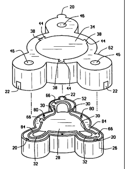
system 24 as best illustrated in Figure 4. The first part of mold system 24 is
female base mold 26 having a positioning wall 52 along periphery 56 of
interior
surface 50 and a molding surface 54 comprised of a center cavity 28, used to
'form one anterior surface 14 or posterior surface 16 of optic portion 12, one
or
more but preferably two junction cavities 30 in fluid connection with center
cavity
28 and at least one haptic element cavity 32 in fluid connection with junction
cavities 30. Surrounding center cavity 28, junction cavities 30 and haptic
element cavity 32 is extended edge 84 to eliminate material flow between molds
to prevent flash. Base mold 26 is sized as needed according to the article to
be
manufactured using the same. For the manufacture of IOLs 10, base mold 26 is
approximately 20 to 35 mm but preferably approximately 25 to 35 mm in length
for ease in handling, approximatelylO to 20 mm but preferably approximately 15
to 20 mm in width for ease in handling and approximately 10 to 20 mm but
preferably 15 to 20 mm in height for ease of handling. Each-of the molding
cavities of base mold 26 may be sized to be slightly larger in size than the
final
IOL product desired to accommodate for material shrinkage, often tirnes as
high
as 15 percent, during polymerization thereof. Altematively, overflow
reservoirs
66 may be shielded from polymerization whereby nonpolymerized rnaterial
therein may flow into adjacent cavities upon shrinkage of polymerized material
in
the adjacent cavities and be polymerized. Polymerization of material to form
an
il
CA 02400397 2007-02-26
implant is preferably carried out under pressure within the range of
approximately 50,000 pounds per square inch at extended edge 84 and edge
recess 86 to eliminate cosmetic defects in the product formed.
The second part of mold system 24 is center male mold 34 having an
interior surface 50 with a molding surface 58 comprised of an optic cavity 60
used to form the second surface, either anterior surface 14 or posterior
surface
16 of optic portion 12, surrounded by edge recess 86. Edge recess 86 is sized
to accept and work in conjunction with extended edge 84 of female base mold
26. Center male mold 34 is sized to be fully received snugly within
positioning
walls 52 of female base mold 26 and shaped to interlock for axial and
rotational
alignment. To ensure axial and rotational alignment, any of a variety of means
may be used such as for example but not limited to providing base mold 26 and
center male mold 34 with aligning pins 80 and pin recesses 82 on interior
surface 50 thereof, providing shape specific forms to base mold 26 and center
male mold 34 such as illustrated in Figure 4 and/or providing base mold 26 and
center male mold 34 with tab 20 and groove 22 alignment means as illustrated
in
Figure 11. For the manufacture of IOLs 10, center male mold 34 is
approximately 5 to 12 mm but preferably approximately 6 to 10 mm in length to
allow optic cavity 60 to be slightly larger than the final desired optic
diameter,
approximately 8 to 18 mm but preferably approximately 13 to 18 mm in width for
proper fit within positioning walls 52 and approximately 10 to 20 mm but
preferably 15 to 20 mm in height for ease of handling. As noted above, optic
12
CA 02400397 2007-02-26
cavity 60 of center male mold 34 may be sized to be slightly larger in size
than
the final optic portion 12 desired due to material shrinkage during
polymerization
thereof.
The third and fourth mold parts of mold system 24 are haptic molds 62.
Each haptic mold 62 likewise has an interior surface 50 with molding surface
64
comprised of one or more junction cavities 40 and at least one haptic element
cavity 42 in fluid connection with optic cavity 60 surrounded by edge recess
86.
Haptic molds 62 are male molds sized to be fully received within positioning
walls 52 of the female base mold 26 and shaped to interlock for axial and
rotational alignment as described above. Haptic molds 62 are also formed to
have material guides or ports 46 extending from haptic element cavity 42
and/or
junction cavity 40 through to the exterior surface 48 of the haptic mold 62.
For
the manufacture of IOLs 10, haptic mold 62 is approximately 14 to 22 mm but
preferably approximately 18 to 24 mm in length to allow proper fit within
positioning walls 52, approximately 8 to 18 mm but preferably approximately 13
to 18 mm in width to allow proper fit within positioning walls 52 and
approximately 10 to 20 mm but preferably 15 to 20 mm in height for ease of
handling. As noted above, each cavity of haptic mold 62 may be sized to be
slightly larger in size than the final corresponding product part desired due
to
material shrinkage during polymerization thereof.
13
CA 02400397 2007-02-26
Suitable materials from which mold system 24 may be manufactured
include for example but are not limited to polyurethanes, polypropylene,
polyvinyl
chloride or acrylates. In the case of ultraviolet light curing of.the IOL 10
materials, a transparent or translucent material such as polypropylene is
preferred.
The subject preferably four-part mold system 24 is useful to cast mold
intraocular implants such as preferably an IOL 10 having an optic portion 12
and
haptics 18 preferably manufactured from dissimilar biocompatible materials. An
IOL 10 is cast molded in accordance with the present invention by providing a
predetermined quantity of a suitable optic portion 12 molding material into
the
center cavity 28 of base mold 26. The center male mold 34 is then inserted
within positioning walls 52 of female base mold 26 allowing excess molding
material to pass into one or more overflow reservoirs 66. DUring this process,
some molding material flows into junction cavities 30. Shields 68 are then
placed within positioning walls 52 using handles 70 to shield interior surface
50
of base mold 26. Base 72 of shield 68 is dimensioned to be the same as that of
interior surface 50 of haptic mold 62 to ensure proper fit within positioning
walls
52. Shields 68 are preferably fabricated from the same material as rnold
system24 with the addition of an ultraviolet light absorber such as for
example
but not'limited to 2-hydroxy-5-acryloyloxyphenyl-2H-benzotriazoles or
vinylsilytalkoxyarylbenzotriazoles. The molding material between center cavity
28 and optic cavity 60 is then polymerized using methods of polymerization
14
CA 02400397 2007-02-26
known to those skilled in the art such as but not limited to ultraviolet light
or heat
curing. Due to shields 68, the molding material in junction cavities 30 is not
polymerized. Shields 68 are then removed from base mold 26 and haptic molds
62 are then placed within positioning walls 52 of female base mold 26.
Suitable haptic molding material is provided through material guides 46 of
haptic molds
62 to fill junction cavities 30 and 40 and haptic element cavities 32 and 42
with
any excess material flowing into reservoir 66. The haptic molding material is
then polymerized using methods of polymerization known to those skilled in the
art such as but not limited to ultraviolet light or heat curing. Following
polymerization, all three male molds, i.e., the center male mold 34 and both
haptic molds 62, are removed from female base mold 26. IOL 10 is removed
from female base mold 26 through the use of solvents or vibration. IOL 10 is
then optionally polished as needed, sterilized and packaged as customary in
the
art.
As described in detail above, the method of cast molding intraocular
implants such as but not limited to IOLs, the molds suitable for such cast
molding
and the IOLs so produced in accordance with the present invention provides a
relatively inexpensive method of manufacturing implants produced from two or
more dissimilar materials. The present description is provided for purposes of
illustration and explanation. It will be apparent to those skilled in the art
that
modifications and changes may be made to the preferred embodiment described
herein without departing from its scope and spirit.