Note: Descriptions are shown in the official language in which they were submitted.
CA 02400463 2002-06-25
1 Electrician's Fish Tape Reel Assembly and Fish Tape
2 Winder-Puller
3
4
S Technical Field
6 The present invention is directed to a fish tape reel assembly containing a
7 coiled, but somewhat rigid, flexible fish tape, of the type commonly used by
8 electricians to facilitate the placement of cable in conduit in new and
remodeled
9 structures.
11
12 Background Art
13 This invention relates to a fish tape reel assembly which is used to store
coiled,
14 somewhat rigid, but substantially flexible fish tape of the type used to
route electrical
1 S and telephone wire through conduit. The fish tape reel assembly is in the
nature of an
16 annular tape reel formed by mating together two substantially identical
hollow annular
17 segments. A winder-pulley mechanism is mounted between the outer lip of the
two
18 annular segments so that the fish tape contained in the assembly may be
wound and
19 unwound by rotating the winder-pulley mechanism around the periphery of the
reel.
The winder-pulley mechanism also includes a handle and a means for a grasping
the
21 fish tape so that the length of fish tape extended from the reel may be
pulled through
22 conduit using the handle.
23 Presently, fish tape is used to pull electrical, telephone, fiberoptic, or
other
24 wire through conduit. Fish tapes are made of various materials, including
steel and
2S nylon-sheathed fiberglass. The tapes are generally rigid, but flexible
enough so that
26 they may be forced through conduit which often follows an irregular path.
Fish tapes
27 are customarily of substantial length, typically at least SO feet/15.24
meters long and
28 often as long as 200 feet/60.96 meters. The leading end of the tape
customarily
29 contains a fastener to which wire can be connected. Because of their length
and in
order to preserve their rigidity and flexibility without kinking, fish tapes
are
31 customarily coiled inside a reel for storage and transporting.
32 The manner in which an electrician customarily uses the fish tape in
33 conjunction with a fish tape reel is by extending a length of fish tape by
unwinding it
1
CA 02400463 2002-06-25
1 from within a fish tape reel, then pushing the tape through conduit until
the leading
2 edge of the tape reaches the distal opening of the conduit. At the distal
opening of
3 the conduit, the leading edge of a length of wire, the remainder of which is
often
4 coiled upon a spool, is connected to the fish tape. The fish tape is then
pulled through
the conduit by the electrician.
6 The force needed to pull upon the fish tape is often substantial because of
the
7 resistance created by the weight of the length of wire being pulled, the
force required
8 to uncoil the wire from its spool, and the friction between the fish tape
and the walls
9 of the conduit, particularly where the conduit courses an irregular path. It
is often
I O difficult for the electrician, without a pulling tool, to grasp the tape
and pull with
11 sufficient force to retract the tape and the wire from the conduit.
12 Electricians occasionally use pliers to pull fish tape. In practice, the
use of
13 pliers for pulling fish tape is disadvantageous and inefficient because the
pliers slip
14 off the tape and because they can damage the surface of the fish tape or
can kink it if
I S the pulling force is applied in a direction other than directly opposite
to the tensile
16 resistance of the tape.
17 Several other types of pulling tools and devices are disclosed by the prior
art
18 which may be used by electricians. One type, exemplified by U.S. Pat. No.
19 5,484,135, requires that the electrician employ both hands to use the
pulling tool.
20 Another type, exemplified by U.S. Pat. No. 5,022,633, can be employed with
one
21 hand, but has the disadvantage of occasionally causing damage to the
surface of the
22 fish tape or may kink the fish tape if the force applied using the tool is
not directly
23 opposite to the tensile resistance of the fish tape.
24 The use of tools Iike those identified herein suffer the additional
disadvantage
25 that the electrician must customarily alternate use of the pulling tool
with the use of
26 the fish tape reel assembly.
27 Several types of fish tape reels are disclosed by the prior art. In one
type of
28 fish tape reel assembly, exemplified by U.S. Pat. No. 4,092,780, the inside
surface of
29 an outer peripheral wall of the reel is used to constrain the coiled fish
tape. The wall
30 is circumferentially split so that a slot is defined around the periphery
of the reel. The
31 halves of the wall normally meet, but are spread apart by a winder
mechanism which
32 is mounted between the halves of the outer wall. The winder can be rotated
about the
33 outer circumference of the reel in either direction so that the fish tape
is coiled therein
2
CA 02400463 2002-06-25
1 or extended therefrom. This type of fish tape reel does not provide the user
with a
2 mechanism to pull the tape through conduit and the user generally must use
both
3 hands to operate the reel. Thus, in an operation pulling wire through a
conduit, the
4 user must alternately employ a fish tape pulling tool and then employ the
reel to
S rewind the pulled fish tape. In order to avoid excess fish tape remaining
unwound,
6 several iterations of alternate uses of the pulling tool and the reel may be
required.
7 This process is inefficient.
8 A second type of fish tape reel disclosed by the prior art is exemplified by
U.S.
9 Pat. No. 5,056,731. In this type of reel an inner and outer housing are
mated together
to form a chamber. The inner and outer housing rotate relative to one another
such
11 that rotating winds or unwinds a coiled fish tape contained therein. Like
the first type
12 of fish tape reel, this mechanism requires the user to employ both hands in
order to
I3 rewind extended fish tape. Thus, in operation pulling wire through a
conduit, this
14 type of reel also requires the user to alternatively employ a fish tape
pulling tool and
the reel.
I6 A combination pulley and reel is disclosed in U.S. Pat. 5,110,992. This
17 combination stores a fish tape pulling tool in the hub of a reel like the
type disclosed
18 in U.S. Pat. No. 5,056,731. While such storage makes it convenient for the
user to
19 find the fish tape pulling tool, the mechanism still requires the user to
alternately
employ the reel and the pulling tool in an inefficient manner.
21 Prior art reels frequently are constructed with handles on the winder
22 mechanism. These handles are constructed for carrying the fish tape reel,
but they are
23 not constructed so as to allow the handle to be used to pull the fish tape
through the
24 conduit. A fish tape reel of the type with a handle permitting the
electrician to pull
2S the fish tape with the handle of the reel is disclosed in U.S. Pat. No.
6,016,609. This
26 apparatus suffers the disadvantage that pulling with the handle may result
in a bending
27 force being applied to the extended fish tape because the grip of the
handle is not
28 located so that force directly opposite to the tensile resistance of the
fish tape may be
29 conveniently applied.
31
32 Disclosure of Invention
33 It is the object of the invention to provide a fish tape reel assembly and
fish
3
CA 02400463 2002-06-25
1 tape- pulley which can be used simultaneously and efficiently to retract
fish tape
2 extended into conduit and to wind the tape within the fish tape reel. It is
a further
3 object of the invention to provide a fish tape reel assembly and fish tape-
pulley which
4 allows for extended fish tape to be retracted and rewound faster and easier.
It is a further object of the invention to provide a pulling mechanism with
the
6 fish tape reel assembly which has a handle with a grip constructed and
located to
7 allow for the efficient application of force in a direction opposite to the
tensile
8 resistance of the extended fish tape.
9 Yet another object of the invention is to provide a pulling mechanism with
the
fish tape reel assembly which grips the fish tape more securely as greater
force is
11 applied to pull the fish tape.
12 These and other objects of invention are realized by a fish tape reel
assembly
13 in which a winder-pulley is mounted between the two complementary halves of
the
14 fish tape reel assembly such that rotating the winder-pulley about the
outer
circumference of the reel spreads apart the outer lips of the halves and
unwinds a
16 length of coiled fish tape from within the reel which is extended and
protruded
17 through an aperture in the winder-pulley. The winder-pulley includes a
handle slidably
18 mounted in a sleeve formed by two complementary hollow sleeve segments.
19 In one preferred embodiment, the handle is pivotably connected to
connecting
rods which are pivotably connected to two cams mounted within the winder-
pulley.
21 The cams are rotatably mounted opposite each other to form a channel
through which
22 the extended fish tape travels and in a fashion such that rotation of the
cams narrows
23 the channel between the cams and forces them to pinch the fish tape between
their
24 surfaces.
When pulling force is applied to the grip of the handle, the handle and the
26 connecting rods cooperate to rotate each of the cams such that the channel
between
27 the cams is narrowed and the fish tape is pinched between the cams.
Increasing the
28 pulling force on the handle proportionally increases the pinching force
upon the fish
29 tape exerted by the cams.
According to another preferred embodiment of the invention the connecting
31 rods are connected to a single cam rotatably mounted within the winder-
pulley. This
32 single cam is mounted directly opposed to an anvil which is also mounted in
the first
33 sleeve segment such that a channel is formed between the face of the cam
and the
4
CA 02400463 2002-06-25
1 anvil through which the extended fish tape travels. Further, the cam is
mounted so
2 that rotation of the cam narrows the channel between the face of the cam and
the anvil
3 and pinches the fish tape between the anvil and the face of the cam.
4 In both preferred embodiments, a spring connected to the first hollow sleeve
segment and to the handle biases the handle inwardly so that when no pulling
force is
6 applied to the grip, the handle is fully inserted into the sleeve and the
cams are rotated
7 such that the channel through which the fish tape passes is at its maximum
width and
8 the fish tape may be extended unimpeded through the channel.
9
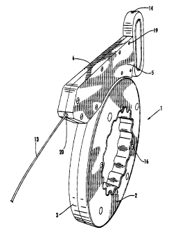
11 Brief Description of Drawings
12 FIG. 1 is a perspective view of the of the invention showing the fish tape
reel
13 assembly with a winder-pulley mechanism with a handle and a length of fish
tape
14 extending from the aperture of the winder-pulley.
FIG. 2 is a plan view of the invention with a partial cut-away view of the
16 winder-pulley mechanism and a portion of the fish tape reel assembly.
17 FIG. 3 is a partial plan view of the invention with a cut-away view of the
18 winder-pulley mechanism illustrating how the handle, connecting rods and
cams
19 cooperate to effect pinching force on the fish tape when the grip of the
handle is
pulled.
21 FIG. 4 is a cross-section of the invention taken along section 4 of FIG. 4.
22
23
24 Best Mode for Carrying Out the Invention
FIG. 1 shows a fish tape reel assembly generally at 1. The assembly is made
26 of two complementary hollow annular reel segments 2 and 3 mated together to
define
27 a hollow fish tape receiving chamber 17, as shown in FIG. 2, in which a
fish tape 13
28 with a plurality of coils is contained. The reel segments can be made of
plastic, like
29 high-density polyethylene, although other materials could be used. The reel
segments
are held in relation to each other by a plurality of bolts 16, or similar
fasteners, such
31 that the inner lip of the first reel segment is directly opposed to the
inner lip of the
32 second reel segment and the outer lip of the first reel segment is directly
opposed to
33 the outer lip of the second. The reel segments are configured such that
their outer lips
S
CA 02400463 2002-06-25
1 may be flexed apart to permit the fish tape to protrude from the fish tape
receiving
2 chamber through the outwardly flexed outer lips.
3 Preferably, the complementary halves of the reel assembly are constructed so
4 that the inner surface of the annular reel assembly provides a surface
readily grasped
by the user.
6 Turning to the winder-puller mechanism, as shown in FIG. 1, the mechanism
7 is constructed of a first sleeve segment 5 and second sleeve segment 6 which
are
8 mated together to define a hollow enclosed sleeve 18; depicted in FIG. 2.
The sleeve
9 segments may be formed of plastic, like high-density polyethylene, or some
other
suitable material and are held in relation to one another by screws 19 or
other similar
11 fastener. One end of the sleeve formed by the sleeve segments is
constructed so that a
12 handle 14 with a connecting portion can be slidably inserted into the
sleeve. The
13 other end of the sleeve is constructed so that an aperture 20 is formed
through which
14 the extended fish tape 13 may protrude.
The first and second sleeve segments are fashioned so that when they are
16 mated together the winder-puller mechanism may be rotatably mounted between
the
17 outwardly flexed outer lips of the annular reel assembly. The fish tape 13
protrudes
18 from inside the reel, through the outwardly flexed lips of the reel and
through a
19 corresponding opening 15 in the winder-puller mechanism and then through
the
aperture 20 at the end of the winder-puller mechanism opposite the handle.
21 The connecting portion of the handle 14 is pivotably connected to a
plurality
22 of connecting rods. In the preferred embodiment depicted in the drawings, a
first
23 connecting rod 10 and second connecting rod 12 are pivotably connected to a
first
24 cam 7. See FIG. 4. Two connecting rods are similarly connected to the
second cam
8. The cams can be constructed of steel or other material which will firmly
pinch the
26 fish tape, but will not damage the surface of the tape.
27 The first and second cam are rotatably mounted to the second sleeve segment
28 6 adjacent to the aperture 20 through which the fish tape 13 protrudes.
Further, they
29 are mounted directly opposite one another and form a channel between their
opposing
faces of sufficient width that the fish tape may extend through the channel
unimpeded.
31 They are also mounted such that rotation of the first and second cams
narrows the
32 channel between their opposing faces and so that the cams pinch the fish
tape
33 extending through the channel.
6
CA 02400463 2002-06-25
I The grip of the handle is configured such that when a user exerts pulling
force
2 upon it, see FIG. 3, the force is applied directly opposite to the tensile
resistance of the
3 fish tape protruding through the aperture 20 of the winder-pulley mechanism.
This
4 orientation of the grip minimizes the likelihood that a user will apply a
bending force
to the extended fish tape.
6 Accordingly, as shown in FIG. 3., when the grip of the handle 14 is pulled
in
7 the direction opposite to the extended fish tape 13, the handle 14 and the
connecting
8 rods 10 & 12 cooperate to rotate the first cam 7. Additional connecting rods
similarly
9 cooperate to rotate the second cam 8, such that the channel formed between
the
opposing faces of the first and second cams is narrowed and the cams pinch the
fish
11 tape between their opposing faces.
12 One end of a coiled metal spring 9 is connected to the first sleeve segment
6
13 and the second end is connected to the connecting portion of the handle 14
such that
14 the handle is biased inwardly.
The fish tape reel assembly and winder mechanism is operated as follows. In
16 order to unwind and extend the fish tape contained in the reel, the user
grasps a
17 portion of the inner surface of the annular reel assembly with one hand and
the top of
18 the winder-pulley mechanism with the other. The user rotates the winder-
pullet
19 mechanism about the outer circumference of the reel in the direction of the
grip of the
handle on the winder-pulier mechanism. This action uncoils a portion of the
fish tape
21 from within the reel assembly so that it may be fed within a conduit or the
like. When
22 the user desires to pull and rewind the fish tape, the user grasps the grip
of the handle
23 of the winder-pulley mechanism with one hand and pulls to retract the
extended fish
24 tape from within a conduit or the like. When a sufficient length of fish
tape is
retracted the user grasps a portion of the inner surface of the reel assembly
with the
26 other hand and pushes forward on the grip of the handle to rotate the
winder-pulley
27 mechanism around the outer circumference of the reel assembly in the
direction of the
28 aperture of the winder-pullet. This action rewinds the fish tape within the
reel
29 assembly. The user can then alternately pull on the grip, retracting the
fish tape from
within the conduit or the like and then push on the grip to rotate the winder-
pullet
31 around the reel assembly and rewind the fish tape in a convenient and
efficient way.
32
33
7
CA 02400463 2002-06-25
Industrial Applicability
2 The invention may be used by electricians and others in deploying
3 cable or wire in new or existing conduit in structures under construction or
being
4 remodeled. It is particularly useful for installing wire through existing
conduit in
structures undergoing renovation.
15
25
8