Note: Descriptions are shown in the official language in which they were submitted.
CA 02400750 2002-08-21
WO 01/65100 PCT/US01/06733
Auxiliary Power Unit
Technical Field
The present invention pertains to auxiliary power units for the co-generation
of heat
and power for indoor use wherein the auxiliary power unit includes an external
combustion
engine and in particular, a Stirling cycle engine.
Background of the Invention
An auxiliary power unit ("APU") consists of an engine and an electric
generator.
Thermal energy of a burning fuel is converted to mechanical energy in the
engine of the APU
and mechanical energy is converted to electrical energy in the generator of
the APU. One
advantage of an APU is that it is a portable size such that it can be easily
transported and used
in a remote location, such as a construction site, cell tower or cabin, that
is not connected to
the local power grid. APU's are also important for providing emergency backup
power for
businesses and homes during a power outage.
Small and portable APU's using an internal combustion engine are widely
available.
For example, a 350W APU weighs as little as 20lbs while a 1kW APU weighs
around 70lbs.
However, APU's which use an internal combustion engine cannot be used in a
closed
environment because of the toxic emissions generated by the internal
combustion engine.
Even if the exhaust fumes were vented to the outside air, the noise generated
by the internal
combustion engine makes it very unappealing to a user. The venting of the
exhaust fumes
also reduces the overall efficiency of the system by about 35% due to the loss
of the thermal
energy carried away by the exhaust gases. Internal combustion engines are
further
disadvantaged by their high maintenance costs and short lifetimes of the order
of 100
operating hours.
Also known in the prior art are co-generation units and heat pumps which use
external
combustion engines, such as Stirling cycle engines. However, these co-
generation units are
typically quite large (and therefore not portable) as dictated by the size of
the external
combustion engine. In addition, the exhaust fumes must still be vented to the
outside air. As
discussed above, venting of the exhaust fumes reduces the overall efficiency
of the system
1
CA 02400750 2008-07-03
2229/106WO
due to the loss of the thermal energy carried away by the exhaust gases and
requires
additional hardware.
One type of external combustion engine which may be used to power an APU is a
Stirling cycle engine. A Stirling cycle engine produces both mechanical energy
and heat
energy. The history of Stirling cycle engines is described in detail in
Walker, Stirling
Engines, Oxford University Press (1980). The principle of
operation of a Stirling engine is well known in the art.
One disadvantage of a Stirling cycle engine in comparison to an internal
combustion
engine is the longer response time of a Stirling cycle engine to sudden
changes in the load
placed on the engine. The response time of a Stirling cycle engine is limited
by the heat
transfer rates between the external combustion gases and the internal working
fluid of the
engine and may be on the order of 30 seconds. The response time of an internal
combustion
engine, on the other hand, is very short because the combustion gas is the
working fluid and
can be directly controlled by the fuel flow rate. Prior attempts to increase
the responsiveness
of a Stirling cycle engine provided a variable dead space for the working
fluid as described in
U.S. Patent No 3,940,933 to Nystrom and U.S. Patent 4,996,841 to Meijer or
controlled the
pressure of the working fluid as described in U.S. Patent 5,755,100 to Lamos.
However, both these approaches tend to increase the complexity, size, and
weight
of the engine design.
Summary of the Invention
In accordance with one aspect of the invention, in one of its embodiments, a
method
for providing auxiliary electrical power and heat to an indoor area of a house
includes
generating mechanical energy and thermal energy using an external combustion
engine, the
external combustion engine burning a fuel and having substantially complete
combustion and
converting the mechanical energy generated by the external combustion engine
into electrical
power using a generator coupled to the external combustion engine. The
external combustion
engine and generator are placed in the indoor area such that the thermal
energy generated by
the external combustion engine heats an area surrounding the external
combustion engine.
The external combustion engine and generator may be contained within a
portable housing.
2
CA 02400750 2002-08-21
WO 01/65100 PCT/US01/06733
In a preferred embodiment, the external combustion engine is a Stirling cycle
engine. In other
embodiments, the fuel burned by the external combustion engine may be propane
or natural
gas. In accordance with another embodiment of the invention, the electrical
power may direct
current power or alternating current power.
In accordance with another aspect of the invention, in one of its embodiments,
an
auxiliary power system for providing electrical power and heat to an indoor
area of a house
includes an external combustion engine for generating mechanical energy and
thermal energy,
the external combustion engine burning a fuel and having substantially
complete combustion
and a generator, coupled to the external combustion engine, the generator for
converting the
mechanical energy of the external combustion engine to electrical power. The
system further
includes a first power output for providing electrical power and a portable
housing
containing the external combustion engine and the generator. The thermal
energy generated
by the external combustion engine heats the an area surrounding the portable
housing. In a
preferred embodiment, the external combustion engine is a Stirling cycle
engine. The
housing may also be mounted in a window or on a wall of the indoor area.
The auxiliary power system may further include a battery for providing
starting power
to the external combustion engine and for providing power to the first power
output. A
sensor is coupled to the battery to produce an output signal. The charge level
of the battery
may be determined based in part on the output signal of the sensor. In one
embodiment, the
output signal represents the battery voltage and current. In another
embodiment, the auxiliary
power system further includes an inverter coupled to the first power output
for converting
direct current power to alternating current power and a second power output
for providing
alternating current power. In yet another embodiment, the auxiliary power
system further
includes an air conditioning module for cooling the atmosphere surrounding the
housing.
In accordance with yet another aspect of the present invention, a system for
controlling the power output of a thermal engine having a heater head,
includes a burner for
delivering heat to the heater head of the engine and having an exhaust gas
product, a fuel
supply regulator for delivering fuel to a burner at a specified rate of fuel
delivery and a blower
for delivering air to the burner. In one embodiment, the system further
includes an input for
receiving a signal related to a specified temperature of operation of the
burner, a sensor for
3
CA 02400750 2002-08-21
WO 01/65100 PCT/US01/06733
monitoring an oxygen concentration in the exhaust gas product of the burner
and a controller
for governing the rate of fuel and air delivery based at least on the input
related to the
specified temperature of operation and the oxygen concentration in the exhaust
gas product.
The input for receiving a signal may include a slew rate limiter.
In another embodiment, the system for controlling the power output of a
thermal
engine further includes a head temperature sensor for measuring the
temperature of the heater
head and a controller for governing the rate of fuel and air delivery based at
least on the
temperature of the heater head. the system may further include a sensor for
monitoring an
oxygen concentration in the exhaust gas where the controller includes a
controller based at
least on the temperature of the heater had and the oxygen concentration in the
exhaust gas
product.
In a further embodiment, the head temperature sensor is disposed in a region
of and
exterior surface of the heater head shadowed from flow of the exhaust gas. The
system may
also include an air mass flow sensor for measuring the mass of air delivered
to the burner
where the controller for governing the rate of fuel and air delivery includes
a controller based
at least on the temperature of the heater head and the mass of air delivered
to the burner.
In accordance with another embodiment of the invention, a system for
controlling;the
power output of an external combustion engine having a crankshaft includes a
generator for
regulating the speed of the external combustion engine, an amplifier for
transforming power
form the generator to a power output and providing a load on the generator and
a battery for
storing power and providing power to a power output. The speed and temperature
of the
external combustion engine are controlled in a manner to maintain a set of
desired battery
conditions.
In accordance with yet another aspect of the invention, a method for operating
the
burner of an external combustion engine includes delivering air to the burner
through a
constant cross-sectional area in transition from a radial flow inward to an
axial flow
downward, delivering the air to the burner at a speed greater than the flame
speed of a fuel-air
mixture and stabilizing a flame produced in the burner using a swirler for
conveying radially
inwardly flowing air.
An auxiliary power system for providing electrical power to a load, in
accordance
4
CA 02400750 2002-08-21
WO 01/65100 PCT/US01/06733
with another aspect of the invention, includes an external combustion engine
having an
engine temperature and having a rotating crankshaft characterized by a
velocity, a generator
for regulating the velocity of the crankshaft and producing electrical power,
an amplifier for
transferring electrical power from the generator to a load, a battery having a
charge state and a
controller for commanding the engine temperature and velocity based in part on
the charge
state of the battery.
In accordance with a further embodiment of the invention, a system for
providing
power to a personal transport vehicle having a set of wheels including at
least one member
and a wheel motor coupled to the set of wheels for causing, when powered,
locomotion of the
personal transport vehicle includes an external combustion engine for
generating mechanical
energy and thermal energy, the external combustion engine burning a fuel in a
burner and
having substantially complete combustion such that the exhaust emissions from
the external
combustion engine are below a predetermined exhaust level. The system further
includes a
fuel supply for providing a fuel to the burner at a specified rate of fuel
delivery, a generator
for converting the mechanical energy produced by the external combustion
engine to
electrical power and a battery having an input and an output, the battery
input coupled to the
generator and the battery output coupled to the wheel motor, the battery for
storing electrical
energy provided from the generator at the battery input and for providing
power to the wheel
motor at the battery output.
A mobile auxiliary power unit, in accordance with a further embodiment of the
invention, includes an external combustion engine having a crankshaft
characterized by a
velocity and a heater head characterize by a head temperature, the external
combustion engine
for generating mechanical energy and thermal energy, the external combustion
engine burning
a fuel and having substantially complete combustion such that exhaust
emissions from the
external combustion engine are below a predetermined exhaust level. A
generator having an
output, is coupled to the crankshaft of the external combustion engine and
converts the
mechanical energy produced by the external combustion engine into electrical
power, the
electrical power provided to the output of the generator. A battery having a
battery output is
coupled to the output of the generator. The battery characterized by a state
of charge and
provides starting power to the external combustion as well as power to the
battery output.
5
CA 02400750 2002-08-21
WO 01/65100 PCT/US01/06733
The mobile auxiliary power unit further includes a controller in signal
communication with
the external combustion engine, the generator and the battery. The controller
governs the
velocity of the crankshaft and the temperature of the heater head based at
least on the state of
charge of the battery. A wheel motor is coupled to the battery output and to a
set of wheels,
including at least one member such that the wheel motor when powered by the
battery, drives
the set of wheels causing the locomotion of the mobile auxiliary power unit.
In accordance
with another embodiment, the mobile auxiliary power unit may include a
platform coupled to
the set of wheels, the platform for supporting a user.
Brief Description of the Drawings
The invention will be more readily understood by reference to the following
description taken with the accompanying drawings, in which:
FIG 1 is a schematic block diagram of an auxiliary power unit in accordance
with, a
preferred embodiment of the invention.
FIG 2 is a schematic block diagram of an auxiliary power unit in accordance
with-an
alternative embodiment of the invention.
FIG 3 is a cross section view of a Stirling cycle engine in accordance with a
preferred
embodiment of the invention.
FIG. 4A is a schematic block diagram of the power control system for the
engine of
the APU of Figure 1 in accordance with an embodiment of the invention
FIG. 4B is a schematic block diagram of a method of control for the power
control
system of Figure 4A in accordance with an embodiment of the invention.
FIG. 5 illustrates the circuitry for the power control system in Figure 6 in
accordance
with an embodiment of the invention.
FIG. 6 is a schematic block diagram of the power control system of the APU of
Figure
1 including the burner controller in accordance with an embodiment of the
invention.
FIG. 7 is a schematic block diagram of the power control system of the APU of
Figure
1 including the burner controller in accordance with an alternative embodiment
of the
invention.
FIG 8a is a side view in cross section of the burner and exhaust heat recovery
6
CA 02400750 2002-08-21
WO 01/65100 PCT/US01/06733
assembly, in accordance with an embodiment of the invention.
FIG. 8b shows a perspective top view of a heater head including heat transfer
pin
arrays in accordance with an embodiment of the invention.
FIG. 9a shows a cross-sectional view from the side of a fuel intake manifold
for a
Stirling cycle engine in accordance with a preferred embodiment of the
invention.
FIG. 9b shows a cross-sectional view from the top of the fuel intake manifold
of Fig.
9a taken through cut BB.
FIG.9c is a cross-sectional view from the top of the fuel intake manifold of
Fig. 9a
taken through cut AA, showing the fuel jet nozzles.
FIG. 10 is a cross section of the burner and heater-head assembly showing the
placement of a flame detection thermocouple in accordance with an embodiment
of the
invention.
FIG. 11 is a cross section of the burner and heater head assembly showing the
placement of a flame detection thermocouple in accordance with an alternative
embodiment
of the invention.
FIG. 12 is a front view of an APU where the front panel of the enclosure has
been
removed for interior viewing in accordance with an embodiment of the
invention.
FIG. 13 is a back view of the embodiment of Figure 14 in accordance with an
embodiment of the invention.
FIG. 14 is a schematic block diagram of an auxiliary power unit and air
conditioning
system in accordance with an embodiment of the invention.
FIG. 15 is a schematic diagram of a scooter utilizing the auxiliary power unit
in
accordance with an embodiment of the invention.
Detailed Description of Preferred Embodiments
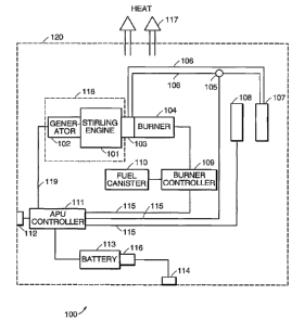
Figure 1 is a schematic block diagram of an auxiliary power unit ("APU") 100
in
accordance with a preferred embodiment of the invention. APU 100 includes an
external
combustion engine 101 coupled to a generator 102. In a preferred embodiment,
the external
combustion engine 101 is a Stirling cycle engine. The outputs of the Stirling
cycle engine
101 during operation include both mechanical energy and residual heat energy.
Heat
7
CA 02400750 2002-08-21
WO 01/65100 PCT/US01/06733
produced in the combustion of a fuel in a burner 104 is applied as an input to
the Stirling
cycle engine 101, and partially converted to mechanical energy. The
unconverted heat or
thermal energy accounts for 65 to 85% of the energy released in the burner
104. This heat is
available to provide heating to the local environment around the APU in two
forms: a smaller
flow of exhaust gas from the burner 104 and a much larger flow of heat
rejected at the cooler
103 of the Stirling engine. The exhaust gases are relatively hot, typically
100 to 300 C, and
represent 10 to 20% of the thermal energy produced by the Stirling engine 101.
The cooler
rejects 80 to 90% of the thermal energy at 10 to 20 C above the ambient
temperature. The
heat is rejected to either a flow of water or, more typically, to the air via
a radiator 107.
Stirling cycle engine 101 is of a size such that the APU 100 is portable. A
portable APU that
provides both electric power and heat to indoor areas is typically less than
5kW. Larger units
would reject too much energy to be used in an indoor area.
As shown in Figure 1, Stirling engine 101 is powered directly by a heat source
such as
burner 104. Burner 104 combusts a fuel to produce hot exhaust gases which are
used to drive
the Stirling engine 101. A burner control unit 109 is coupled to the burner
104 and a fuel
canister 110. Burner control unit 109 delivers a fuel from the fuel canister
110 to the burner
104. The burner controller 109 also delivers a measured amount of air to the
burner 104 to
advantageously ensure substantially complete combustion. The fuel combusted by
burner
104 is preferably a clean burning and commercially available fuel such as
propane. A clean
burning fuel is a fuel that does not contain large amounts of contaminants,
the most important
being sulfur. Natural gas, ethane, propane, butane, ethanol, methanol and
liquefied petroleum
gas ("LPG") are all clean burning fuels when the contaminants are limited to a
few percent.
One example of a commercially available propane fuel is HD-5, an industry
grade defined by
the Society of Automotive Engineers and available from Bernzomatic. In
accordance with an
embodiment of the invention, and as discussed in more detail below, the
Stirling engine 101
and burner 104 provide substantially complete combustion in order to provide
high thermal
efficiency as well as low emissions. The characteristics of high efficiency
and low emissions
are key to using the APU 100 indoors.
Generator 102 is coupled to a crankshaft (not shown) of Stirling engine 101.
It should
be understood to one of ordinary skill in the art that the term generator
encompasses the class
8
CA 02400750 2002-08-21
WO 01/65100 PCT/US01/06733
of electric machines such as generators wherein mechanical energy is converted
to electrical
energy or motors wherein electrical energy is converted to mechanical energy.
The generator
102 is preferably a permanent magnet brushless motor. A rechargeable battery
113 provides
starting power for APU 100 as well as direct current ("DC") power to a DC
power output
112. In a further embodiment, APU 100 also advantageously provides alternating
current
("AC") power to an AC power output 114. An inverter 116 is coupled to the
battery 113 in
order to convert the DC power produced by battery 113 to AC power. In the
embodiment
shown in Figure 1, the battery 113, inverter 116 and AC power output 114 are
disposed
within an APU enclosure 120. In an alternative embodiment, as shown in Figure
2, the
battery 113, inverter 116 and the APU power output 114 may be separate from
the APU
enclosure 120.
In the course of operation, Stirling engine 101 also produces heat 117 from,
for
example, the exhaust gases of the burner 104 as well as the supply and
extraction of heat from
a working fluid. Accordingly, when used inside of a building, the excess heat
produced by
the Stirling engine 101 may be used to advantageously heat the atmosphere
surrounding the
APU 100. In this manner, the APU 100 may be used to provide both electrical
power and
heat to an indoor area such as a building or a residence.
The operation of Stirling cycle engine 101 will now be described in more
detail with
respect to Figure 3 which is a cross-sectional view of a Stirling engine in
accordance with an
embodiment of the invention. The configuration of Stirling engine 101 shown in
Figure 3 is
referred to as an alpha configuration, characterized in that a compression
piston 300 and an
expansion piston 302 undergo linear motion within respective and distinct
cylinders:
compression piston 300 in a compression cylinder 304 and expansion piston 302
in an
expansion cylinder 306. The alpha configuration is discussed by way of example
only, and
without limitation of the scope of any appended claims.
In addition to compression piston 300 and expansion piston 302, the main
components of Stirling engine 101 include a burner (not shown), a heater heat
exchanger 322,
a regenerator 324, and a cooler heat exchanger 328. Compression piston 300 and
expansion
piston 302, referred to collectively as pistons, are constrained to move in
reciprocating linear
motion within respective volumes 308 and 310 defined laterally by compression
cylinder 304
9
CA 02400750 2002-08-21
WO 01/65100 PCT/US01/06733
and expansion cylinder liner 312. The volumes of the cylinder interior
proximate to the
burner heat exchanger 322 and cooler heat exchanger 328 will be referred to,
herein, as hot
and cold sections, respectively of engine 101. The relative phase (the "phase
angle") of the
reciprocating linear motion of compression piston 300 and expansion piston 302
is governed
by their respective coupling to drive mechanism 314 housed in crankcase 316.
Drive
mechanism 314 may be one of various mechanisms known in the art of engine
design which
may be employed to govern the relative timing of pistons and to interconvert
linear and rotary
motion.
Compression piston 300 and expansion piston 302 are coupled, respectively, to
drive
mechanism 314 via a first connecting rod 318 and a second connecting rod 320.
The volume
of compression cylinder 308 is coupled to cooler heat exchanger 328 via duct
315 to allow
cooling of compressed working fluid during the compression phase. Duct 315,
more
particularly, couples compression volume 308 to the annular heat exchangers
comprising
cooler heat exchanger 328, regenerator 324, and heater heat exchanger 322. The
burner (not
shown) combusts a fuel in order to provide heat to the heater heat exchanger
322 of a heater
head 330 of the Stirling engine. The expansion cylinder and piston are
disposed within a
heater head 330 such that the working fluid in the expansion cylinder may be
heated via the
heater heat exchanger 322.
Returning to Figure 1, the Stirling cycle engine 101 and generator 102 are
disposed
within a pressure vessel 118. The pressure vessel 118 contains a high pressure
working fluid,
preferably helium or nitrogen at 20 to 30 atmospheres pressure. The expansion
cylinder and
piston (shown in Figure 3) of the Stirling engine 101 extend through the
pressure vessel 118
and a cold collar (or cooler) 103. The end of the expansion cylinder
(including heater head
330) is contained within the burner 104. The cold collar 103 circulates a
cooling fluid
through cooling lines 106 and through radiator 107. The cooling fluid is
pumped through the
cold collar 103 by a cooling pump 105. A fan 108 forces air past the radiator
107 thereby
heating the air and cooling the cooling fluid. The heated air 117 may then be
forced through
openings in the APU enclosure 120 to heat the surrounding area such as the
room of a
building. In alternative embodiments, the excess heat 117 created by the
combustion within
burner 104 may be directly provided to the surrounding ambient air.
CA 02400750 2002-08-21
WO 01/65100 PCT/US01/06733
The pressure vessel 118 has a pass-through port for an electrical connection
119
between the generator 102 contained within the pressure vessel 118 and an APU
controller
111. The APU controller 111 supplies power to the cooling pump 105, fan 108,
and the
burner controller 109 through power supply lines 115. The APU controller 111
also controls
the power output of the APU as well as the charge level of the battery 113 by
varying the
speed and temperature of the Stirling engine. APU controller 111 provides
command signals
to the burner control unit 109 in order to control the temperature of the
Stirling engine 101.
APU controller 111 also provides command signals to generator 102 in order to
control the
speed of the Stirling engine 101.
The power output of generator 102 and Stirling engine 101 are controlled using
APU
controller 111 so as to maintain the optimal charge and voltage levels in the
battery 113.
Electrical loads will reduce the charge and voltage of the battery 113 causing
the APU
controller 111 to command additional power from the engine. Figure 4A is a
schematic block
diagram of the power control system of the APU included in the APU controller
111 (shown
in Figure 1) in accordance with an embodiment of the invention. The power
control system
controls the speed and temperature of the Stirling engine in order to provide
the necessary
power to meet the demand (or load) placed on the APU and maintain the charge
level of the
battery. The power control system as shown in Figure 4A includes a
motor/generator 402, a
motor-amplifier 405, a battery 413 and an inverter 416.
As discussed above with respect to Figure 1, the generator 402 is coupled to
the
crankshaft of a Stirling engine (not shown). The Stirling engine provides
mechanical power
(Pmecb) to the generator 402 which in turn converts the mechanical power to
three-phase
electrical power. Generator 402 also, as discussed in more detail below, acts
as an adjustable
load on the engine in order to control the speed of the engine. Generator 402
delivers the
three-phase electrical power to motor-amplifier 405. Motor-amplifier 405
transfers electrical
power produced by the motor generator 402 to a high voltage DC bus (Pamp). The
power
provided to the high voltage DC bus (Pamp) is delivered to a DC to DC
converter 406 (Pd d h)
which steps down the power to a low voltage DC bus for delivery to the battery
413 (Pba).
The DC to DC converter 406 may also be used to step up the power to the high
voltage DC
bus used for power control and AC power conversion. Alternate embodiments may
omit the
11
CA 02400750 2002-08-21
WO 01/65100 PCT/US01/06733
DC to DC converter and connect the high voltage DC bus directly to the battery
413. Battery
413 is used to start the Stirling engine and to provide power to auxiliary
circuitry 408 of the
APU such as fans, pumps, etc., as well as to provide output power when the
load on the APU
exceeds the power produced by the motor/generator 402. As described further
below, battery
413 acts as an energy reservoir during the operation of the APU.
An emergency shunt 407 may be used to remove excess power from the high
voltage
DC bus in the case of an overvoltage condition in either DC bus. In one
embodiment, the
emergency shunt resistors are located in the water of the radiator 107 (shown
in Figure 1). In
this manner, the excess heat produced by the shunt resistors when they are
utilized to remove
excess power, is advantageously absorbed by the same system used to dissipate
the excess
heat of the APU (i.e., radiator 107). An inverter 416 is used to deliver AC
power (Poõ ,) to an
external appliance or load 410. The inverter 416 draws power (P;",,) from the
DC bus.
The charge level of the battery 413 reflects changes in the output load 410.
In order to
provide the required power output, the power control system of Figure 4A
attempts to keep
the battery 413 at its optimum charge, without overcharging, in response to
changes in the
output load 410. The optimum charge is not necessarily a full charge and may
be 80-100% of
the full charge. The optimum charge is a tradeoff between keeping the battery
ready for
extended periods of discharge and increasing the battery cycle life. Charging
the battery to
nearly 100% of full charge maximizes the availability of the battery for
extended periods of
discharge but also stresses the battery, resulting in a shorter battery cycle
life. Charging the
battery to less than full charge reduces the stresses placed on the battery
and thereby extends
the battery cycle life but also reduces the energy available in the battery
for sudden load
changes. The selection of the optimum charge will depend on the expected load
variations
placed on the APU and the battery capacity and is well within the scope of one
of ordinary
skill in the power management art. In a preferred embodiment, the optimum
charge is set at
90% of full charge. Another goal of the power control system is to reduce the
fuel
consumption of the engine by maximizing the efficiency from fuel input to
power output.
The power control system of Figure 4A adjusts the engine temperature and the
engine speed
in order to produce the desired battery charge and thus, the required power
output.
The charge of the battery 413 may be roughly estimated by the battery voltage.
As
12
CA 02400750 2002-08-21
WO 01/65100 PCT/US01/06733
described above, differences between the load power (Pout) and the power
generated by the
Stirling engine (Pmech or PamP) will result in power flow to or from the
battery 413. For
example, if the engine does not produce enough power to meet the demand of the
load 410,
the battery 413 will provide the remaining power necessary to support the load
410. If the
engine produces more power than required to meet the demand of the load 410,
the excess
power may be used to charge the battery 413. The power control system
determines whether
it is necessary to command the engine to produce more or less power in
response to changes
in the load. The engine speed and engine temperature are then adjusted
accordingly to
produce the required power. When the battery 413 is being discharged (i.e. the
demand from
the load 410 is greater than the power produced by the engine for extended
periods of time),
the engine temperature and speed are adjusted so that the engine produces more
power.
Typically, the engine temperature and speed are increased in order to produce
more power.
Preferably, when more power is needed, raising engine temperature is given
preference over
raising engine speed. Conversely, when the battery 413 is being charged for
extended periods
of time (i.e., the engine is producing more power than the load 410 demands),
the engine
temperature and speed are decreased to decrease the amount of power produced
by the
engine. Typically, the engine temperature and speed are adjusted to decrease
the amount of
power produced by the engine. Preferably, when less power is needed, reducing
engine speed
is given preference over reducing engine temperature.
Once the power control system determines the desired engine temperature and
speed
based on the desired battery power, the power control system sends a
temperature command
to the burner control unit 109 (shown in Figure 1) indicating the desired
engine temperature
and a speed command to the generator 402 indicating the desired engine speed.
As
mentioned above, the speed of the engine may be controlled by modulating the
torque applied
to the crankshaft of the engine by the motor/generator 402 using the motor
amplifier 405. As
such, the generator 402 acts as an adjustable load on the engine. When the
generator 402
increases demand on the engine, the load on the crankshaft increases and
thereby slows down
the speed of the engine. The motor amplifier 405 adjusts the motor current in
order to obtain
the necessary torque in the motor and accordingly the necessary engine speed.
A Stirling cycle engine (or other external combustion engine) typically has a
long
13
CA 02400750 2002-08-21
WO 01/65100 PCT/US01/06733
response time to sudden changes in the load (i.e., there is a time lag between
the engine's
receipt of a increase or decrease temperature command and the engine reaching
the desired
temperature). The power control system, therefore, is designed to account for
the lengthy
response time of a Stirling cycle engine. For a sudden increase in the load
410, the torque
load applied by the generator 402 on the crankshaft of the engine is reduced,
thereby allowing
the crankshaft to speed up and temporarily maintain an increased power output
of the
generator 402 until an increased temperature command sent to -the burner
control unit 109
(shown in Figure 1) takes effect. For a sudden load decrease, the torque
applied by the
generator 402 on the crankshaft of the engine may be increased in order to
slow down the
crankshaft and decrease the power output until a decreased temperature command
sent to the
burner control unit takes effect. The excess charge or power produced by the
generator 402
may be used to charge the battery 413. As discussed above, any further excess
electrical
energy may also be directed to the emergency shunt 407. The process of
controlling the
temperature of the engine using the burner control unit 109 is described in
more detail below
with respect to Figures 6-11.
Figure 4B is a schematic block diagram of a method for determining the desired
engine temperature and speed in order to provide the required electrical power
to maintain the
optimal charge for the battery and meet the applied load. First, at block 420,
the power
control system estimates the state of charge of the battery. The estimated
battery state of
charge (Qest) is determined using the measured battery current (IB) as well
as, when necessary,
an adjustment current (Iadj) as shown in the following equation:
Qest(t) = Qest(t-dt) +IB(t)dt + Iadj(t)dt, (Eqn. 1)
in block 420. When the engine is first started, the initial estimated state of
charge (Qest) is set
to a preselected value. In a preferred embodiment, the initial state of charge
value is 10% of
full charge. The adjustment current is then used to correct the battery
current such that Qest
approaches a value near the actual state of charge. By selecting a low initial
value for Q,,,, at
startup, faster correction is achieved because a lower value for Qest allows
for a higher
charging current.
The adjustment current may be selected based on the known V-I characteristics
of the
battery. In a preferred embodiment, the battery is a lead-acid battery. The
determination of
14
CA 02400750 2002-08-21
WO 01/65100 PCT/US01/06733
the V-I plane for a particular battery is well within the scope of one of
ordinary skill in the art.
The V-I plane for the battery 413 (shown in Figure 4A) may be divided into
operating
regions where the state of the charge of the battery is reasonably known. The
measured
battery voltage, VB, and battery current, IB, are used to identify the current
state of the battery
in the V-I plane. The estimated charge Qest is then compared to the identified
state of charge
corresponding to the region of the V-I plane in which the measured battery
voltage and
current fall. The adjustment current, Iadj, is estimated by taking the product
of a constant,
which is a function of the measured voltage and current of the battery, and
the difference
between the estimated state of charge Qest and the state of charge estimated
using the V-I
plane and the measured battery voltage and current.
At block 422, a power error P., is determined by comparing the desired battery
power
Pbatdes and the actual battery power PB. The power error Perr is indicative of
whether the APU
must produce more or less power output. The actual battery power PB is the
measured battery
power flowing into the battery (IBVB). The desired battery power may be
estimated using two
methods. The first method is based on the charging voltage of the battery Vchg
and the second
method is based on the estimated state of charge Qest of the battery. In the
following
discussion, the desired battery power estimated using the first method will be
referred to as Pv
and the desired battery power estimated using the second method will be
referred to as PQ.
The first method estimates a desired battery power, Pv, using the charging
voltage of
the battery (Vchg). In a preferred embodiment, Pv is estimated using the
following equation:
PV = Vchg * MAX [Im;n , IB I - Ioc, (Eqn. 2).
The charging voltage Vchg is the optimum battery voltage to keep the battery
charged and is
typically specified by the manufacturer of a particular battery. For example,
in a preferred
embodiment, the lead-acid battery has a charging voltage of 2.45V/cell. Vchg
is multiplied
by the larger of either the measured battery current (IB) or a predetermined
minimum current
value (Irvin). Im;n may be selected based on the known characteristics of the
V-I plane of the
battery. For example, in one embodiment, when the measured battery voltage VB
is much less
than Vchg, Im;n may be set to a high value in order to quickly increase the
voltage of the battery,
VB, up to Vchg. If VB is near Vchg, Imin may be set to a low value as it will
not require as much
additional energy to bring the battery voltage VB up to Vchg. If VB is greater
than Vchg,
CA 02400750 2002-08-21
WO 01/65100 PCT/US01/06733
however, an overcharge current IU, may be subtracted from the greater of IB
and Im,n in order to
avoid an overvoltage condition.
The second method estimates a desired battery power PQ based on the estimated
state
of charge (Qes) of the battery (as determined in block 420). In a preferred
embodiment, PQ is
estimated using the following equation:
PQ = KQ(QG - Qest) - (111buSVbUS - IBVB), (Eqn. 3)
where:
KQ is a gain constant that may be configured, either in design of the system
or
in real-time, on the basis of current operating mode and operating conditions
as well as the preference of the user;
QG is the desired state of charge of the battery;
IbUS is the measured bus current exiting the motor amplifier;
Vbus is the measured bus voltage; and
i1 is an estimated efficiency factor for the DC/DC converter (shown in Figure
4A) between the motor amplifier and the battery.
The desired power PQ is based on the difference between the desired charged
state QG of the
battery and the estimated charge state Q.t of the battery. QG is a
predetermined value
between 0 (fully discharged) and 1 (fully charged) and represents the state of
charge the
controller is trying to maintain in the battery. In a preferred embodiment,
the desired state of
charge of the battery is 90% of full charge. The farther away the estimated
battery charge Qest
is from the desired charge state Qc, the more power which can safely be
requested to charge
the battery. The closer Qest is to QG, the less power that is needed to bring
the battery voltage,
VB, up to Vchg=
The estimation of the desired battery power PQ is also adjusted to account for
possible
load changes. If the load on the APU were suddenly decreased, the excess power
produced
by the engine must be directed elsewhere until the amount of power generated
by the engine
may be reduced (i.e., the system has time to react to the sudden change in
load). The excess
power represents the worst case additional power that could flow into the
battery if the load
were suddenly removed from the system. Accordingly, it is desirable to select
a desired
battery power which leaves room in the battery to absorb the excess power
produced by a
16
CA 02400750 2002-08-21
WO 01/65100 PCT/US01/06733
change in the load. The excess power is subtracted from PQ in order to leave
additional room
in the battery to absorb the excess power. The excess power may be determined
by
comparing the power generated by the engine to the power entering the battery
and is
represented by the term 11IbUSVb,,s - IBVB in Eqn. 3 above. The power
generated by the engine
is estimated using the bus voltage Vbus measured at the motor amplifier and
the bus current Ibus
measured exiting the motor amplifier. The power entering the battery is the
product of the
measured battery voltage and current (IBVB).
At block 422, the minimum of the two estimated desired battery powers Pv and
PQ is
used to determine the power error Pen. The power error Perris the difference
between the
selected desired battery power and the measured power flowing into the battery
as shown by
the following equation:
Pe1r = MIN [Pv, PQ] -IBVB , (Eqn. 4)
The measured power PB flowing into the battery is the product of the measured
battery current
IB and the measured battery voltage VB. As mentioned above, the power error
Perr is
indicative of whether the APU must produce more or less power output. In other
words, if
the actual battery power is less than the desired battery power, the APU will
need to produce
more power (i.e., increase speed and temperature). If the actual battery
voltage is greater than
the desired battery voltage, the APU will need to produce less power (i.e.,
decrease speed and
temperature).
In response to the power error signal Pe,, the power control system produces
an
engine temperature command signal output (T) and an engine speed command
signal output
(co) at block 424 which indicate the engine temperature and speed required to
produce the
desired power. In a preferred embodiment, the engine temperature T is
proportional to the
engine speed and the integral of a function of Pe In this embodiment, T is
governed by the
control law
T = f fdt, (Eqn 5) where:
f = K;tPe~, when comot < comotidle ;
f = K;tPe + Kdrift when Perr_0 and Wmot >_ camot;d,e; and
f = Kdrift when Perr < 0 and comot > cOmotidle=
17
CA 02400750 2002-08-21
WO 01/65100 PCT/US01/06733
In the above control law, wmot is the measured engine speed, Wmotidle is a
predetermined
nominal engine speed, and Kit is a gain constant. When the speed of the engine
is greater than
a nominal motor speed, an additional drift term (Kdrift) is added which has
the effect of slowly
increasing the engine temperature as well as indirectly decreasing the engine
speed to the
nominal speed of the engine. Operation of the engine at the nominal engine
speed maximizes
the efficiency of the engine.
In a preferred embodiment, the speed of the engine (co) is proportional to the
power
error Pe11 and the integral of Pen. and is governed (' by the following
control law:
- AminKpwPerr Kiw J Perrdt (Eqn. 6)
where:
cumin represents the minimum allowable engine speed; and
KpW and KiW are gain constants.
The motor speed, co, is limited to be at least some minimum speed Cumin. The
engine speed is
also limited to a maximum speed COmax to reduce the engine cooling effect when
the speed
increases.
Figure 5 shows the structural details of the power electronics circuitry of
Figure 4A.
The generator 502 is coupled to a battery 513, an inverter 516, an amplifier
505 and an
emergency shunt 507. The behavior of these elements is similar to that
described above with
respect to Figures 4A and 4B.
As discussed above with respect to Figures 4A and 4B, once the power control
system
determines the desired engine temperature and speed required to maintain the
optimal charge
level of the battery, a speed command ((o) is sent to the generator 402 (shown
in Figure 4A)
indicating the desired engine speed and a temperature command (T) is sent to
the burner
control unit 109 (shown in Figure 1) indicating the desired engine speed.
Returning to Figure
1, the burner control unit 109 controls the burner 104 to achieve the desired
engine
temperature. The burner control unit 109 delivers a clean burning fuel,
preferably propane,
supplied from a fuel canister 110 to the burner 104. The burner control unit
109 also delivers
a measured amount of air to the burner 104 to ensure substantially complete
combustion of
the fuel. The burner control unit 109 sets the fuel and air flow rates to
provide the required
engine temperature and to minimize emissions.
18
CA 02400750 2002-08-21
WO 01/65100 PCT/US01/06733
In order to achieve high efficiency and low emissions such that APU 100 may be
used
inside a residence to advantageously provide both electrical power and heat,
Stirling engine
101 and burner 104 provide substantially complete combustion. Preferred
methods of
improving thermal efficiency and providing low emissions of Stirling engine
101 will now be
discussed in more detail in reference to Figures 6-11. Components of such
thermal efficiency
include efficient pumping of an oxidant (typically air, and, referred to
herein as "air") through
the burner 104 to provide combustion, and the recovery of hot exhaust leaving
the heater
head 330 (shown in figure 3) of the Stirling engine. In many applications, air
(or other
oxidant) is pre-heated, prior to combustion, nearly to the temperature of the
heater head 330,
so as to achieve thermal efficiency. There is still a considerable amount of
energy left in the
combustion gases after the heater head of the Stirling engine has been heated,
and, as known
to persons skilled in the art, a heat exchanger may be used to transfer heat
from the exhaust
gases to the combustion air prior to introduction into burner 104. A preheater
assembly is
discussed in more detail below with respect to Figure 8.
In addition, minimizing emissions of carbon monoxide (CO), hydrocarbons (HC)
and
oxides of nitrogen (NOx) requires a lean fuel-air mixture which still achieves
complete
combustion. A lean fuel air mixture has more air than a stoichiometric mixture
(i.e., 15.67
grams of air per gram of propane, for example). As more air is added to the
fuel, the
emissions of CO, HC and NOx decrease until the amount of air is large enough
that the flame
becomes unstable. At this point, pockets of the fuel-air mixture will pass
through the burner
without complete combustion. Incomplete combustion of the fuel-air mixture
produces large
amounts of CO and HC. The CO and HC emissions will continue to increase as
more air is
added to the fuel-air mixture until the flame extinguishes at a Lean Blow-Out
limit ("LBO").
The LBO will increase as the temperature of the incoming air (i.e., the
preheated air)
increases. As a result, the optimal fuel-air ratio decreases as the
temperature of the preheated
air increases during the warmup phase of the engine. Once the engine is warmed
up, the fuel-
air ratio is adjusted to minimize the emissions produced and to maintain a
stable flame. As
used in this description and the following claims, a fuel-air ratio is the
ratio of the mass of the
fuel to the mass of the air flowing into the combustion chamber of the burner.
Accordingly, the fuel-air ratio is first controlled by the burner controller
(shown in
19
CA 02400750 2002-08-21
WO 01/65100 PCT/US01/06733
Figure 1) to provide the optimal fuel-air ratio for ignition. Once the flame
is proved, the fuel-
air ratio is controlled to minimize emissions based upon the temperature of
the preheated air
and the fuel type. The burner control unit then controls the fuel flow rate to
bring the heater
head 330 temperature up to the commanded temperature. The air flow rate is
adjusted in
order to maintain a desired level of oxygen in the exhaust of the engine as
the fuel flow rate
changes and as the air preheat temperature changes.
Figure 6 is a schematic block diagram of the power control system including
the
burner control unit 609. APU controller 611 calculates the required engine
temperature and
engine speed at block 606 as discussed above with respect to Figures 4A and
4B. The desired
engine temperature (i.e. the desired temperature of the heater head) is
provided as a
temperature command input 607 to the burner control unit 609. A slew rate
limiter 601 is
advantageously used to limit the increase in engine temperature so that the
temperature
increase is gradual in order to minimize temperature over- and under-shoot.
Upon receiving a
temperature command 607 from the APU controller 611 for an engine temperature
above a
minimum operating temperature, the burner control unit 609 initiates a
lighting sequence for
the burner 604. A water pump (not shown) and a radiator fan(not shown) are
controlled to
maintain the temperature of the coolant.
A given fuel will only ignite over a limited range of fuel-air ratios. At
ignition, an
ignition fuel-air ratio chosen which is equal to or less than the
stoichiometric fuel-air ratio
corresponding to the fuel being used. In a preferred embodiment, where the
fuel is propane,
the ignition fuel-air ratio is set to 0.1 grams propane per grams air. The
ignition fuel air ratio
is maintained until the flame stabilizes and the temperature of the interior
of the combustion
chamber of the burner 604 increase to a warmup temperature. In a preferred
embodiment, the
ignition fuel-air ratio is maintained until the heater head 330 temperature
reaches 300 C.
Once the flame is stabilized, and the temperature of the combustion chamber of
the
burner reaches the desired warmup temperature, the fuel-air ratio is then
controlled based on
the air preheat temperature and the fuel type. As described above, the optimal
fuel-air ratio of
the fuel-air mixture decreases as the temperature of the preheated air
increases. The optimal
fuel-air ratio first decreases linearly from a "start" fuel-air ratio for room
temperature air to a
"run" fuel-air ratio, for warmed up preheated air temperature. The air is
considered fully
CA 02400750 2002-08-21
WO 01/65100 PCT/US01/06733
warmed up when it exceeds its known ignition temperature. For example, the
ignition
temperature for propane is 490 C. In a preferred embodiment, where the fuel is
propane, the
"start" fuel-air ratio is 0.052 grams fuel to gram air, which results in
approximately 4%
oxygen in the exhaust of the engine. The "run" fuel-air ratio in the preferred
embodiment is
0.026 grams fuel to gram air, which results in approximately 13% oxygen in the
exhaust of
the engine. Once the air reaches its warmed up preheated temperature, the air
flow rate is
adjusted to maintain the optimal fuel-air ratio for the warmed up preheated
temperature. The
air flow rate may be adjusted, for example, in response to a change in the
fuel flow rate or a
change in the air preheat temperature.
In the embodiment of Figure 6, the fuel-air ratio may be determined by
measuring the
air and fuel mass flow rates. The air flow rate may be measured with a
pressure sensor and a
venturi tube at the blower 605. The fuel flow rate may be determined from the
pressure
upstream and downstream of a set of fuel control valves and monitoring which
valves are
currently commanded open. In an alternative embodiment, the fuel- air ratio
may be based on
the measurement of the oxygen content in the exhaust of the APU as shown in
Figure 7. An
oxygen sensor may be placed in the engine to sample the exhaust gas and
measure the
percentage of oxygen in the exhaust.
Returning to Figure 6, the engine temperature (Thead) is measured and compared
to the
desired engine temperature 607 using a feed back loop. The engine temperature
will continue
to be increased (by increasing the fuel and air flow rates) until the engine
temperature reaches
the desired engine temperature. As discussed previously, the slew rate limiter
601 provides a
gradual increase in the temperature to minimize temperature over- and under-
shoot. When
the APU controller 611 commands a heater head temperature below a minimum
heater head
temperature, the burner controller 609 turns off the fuel and air and controls
the water pump
and radiator fan to avoid coolant boil-over.
In addition to providing the optimal fuel-air ratio, the fuel and air
combusted in
burner 604 must be well-mixed with sufficient amounts of oxygen to limit the
emission of
carbon monoxide (CO) and hydrocarbon (HC) and, additionally, must be burned at
low
enough flame temperatures to limit the formation of oxides of nitrogen (NOX).
The high
temperature of pre-heated air, which as described above is desirable for
achieving high
21
CA 02400750 2008-07-03
2229/106WO
thermal efficiency, complicates achieving low emission goals by making it
difficult to premix
the fuel and air and requiring large amounts of excess air in order to limit
the flame
temperature. As used herein, the term "auto-ignition temperature" is defined
as the
temperature at which a fuel will ignite without a temperature-decreasing
catalyst under
existing conditions of air and fuel pressure. The typical preheated air
temperature exceeds the
auto-ignition temperature of most fuels, potentially causing the fuel air
mixture to ignite
before entering the combustion chamber of the burner. One solution to this
problem is to use
a non-pre-mixed diffusion flame. However, since such diffusion flames are not
well mixed,
higher than desirable emissions of CO and NOx result. A detailed discussion of
flame
dynamics is provided by Turns, An Introduction to Combustion: Concepts and
Applications,
(McGraw-Hill, 1996). An increased air flow
provided to limit flame temperature typically increases the power consumed by
an air pump
or blower, thereby degrading overall engine efficiency.
In accordance with an embodiment of the present invention, low emissions and
high
efficiency may be provided by producing a pre-mixed flame even in the presence
of air heated
above the auto-ignition temperature of the fuel, and additionally, by
minimizing the pressure
drop between the air inlet and the flame region thereby minimizing blower
power
consumption.
The term "flame speed" is defined as the speed at which a flame front will
propagate
through a particular fuel-air mixture. Within the specification and the
following claims, the
term "combustion axis" shall refer to the direction of predominant fluid flow
upon
combustion of the fluid.
Typical components of the burner and preheater assemblies, in accordance with
embodiments of the present invention, are described with reference to Figure
8a. The target
range for combustion gases is 1700-2300K, with a preferred range of 1900-
1950K. Operating
temperatures are limited by the strength of heater head 330 which must contain
working fluid
at an operating pressure of typically several atmospheres and by the oxidation
resistance of
the burner structure. Since the strength and oxidation resistance of metals
typically decreases
at high temperatures, it is important to shield metal components from the high
combustion
temperatures. To that end, burner 122 is surrounded by a ceramic combustion
chamber 804,
22
CA 02400750 2002-08-21
WO 01/65100 PCT/US01/06733
itself encased in a metal combustion chamber liner 806, thermally sunk to
heater head 330,
and cooled by incoming air from the preheater path or by exhaust gases 810.
Additionally,
heater head 330 is shielded from direct flame heating by head flame cap 802.
The exhaust
products of the combustion process follow path 808 past heater head 330
through a channel
providing for efficient transfer of heat to the heater head and to the working
gas contained
within the heater head.
The overall efficiency of a thermal engine is dependent in part on the
efficiency of
heat transfer between the combustion gases and the working fluid of the
engine. In order to
increase the efficiency of heat transfer from exhaust products of the
combustion process
generated by burner 122, to the working fluid contained within heater head 330
of the engine,
a large wetted surface area, on either side of heater head 330 is required.
Referring to Figure
3, heater head 330 is substantially a cylinder having one closed end 332
(otherwise referred to
as the cylinder head) and an open end 334. Closed end 332 is disposed in
burner 122 as
shown in Figure 8a. Referring to Figure 8b, in accordance with a preferred
embodiment of
the invention, fins or pins may be used to increase the interfacial area
between the hot fluid
combustion products and the solid heater head 330 so as to transfer heat, in
turn, to the
working fluid of the engine. Heater head 330 may have heat transfer pins 152,
disposed on
the exterior surface as shown in Figure 8b, so as to provide a large surface
area for the
transfer of heat by conduction to heater head 330, and thence to the working
fluid, from
combustion gases flowing from burner 122 (shown in Figure 8a) past the heat
transfer pins.
Heat transfer pins may also be disposed on the interior surface (not shown) of
heater head
330. Interior-facing heat transfer pins serve to provide a large surface area
for the transfer of
heat by conduction from heater head 330 to the working fluid.
Depending on the size of heater head 330, hundreds or thousands of inner
transfer
pins and outer heat transfer pins may be desirable. In accordance with certain
embodiments
of the invention, individual arrays of pins 150, comprise arcuate fractions of
the
circumferential distance around the heater head 330. This is apparent in the
top view of the
heater head assembly shown in perspective in Fig. 8b. Between successive heat
transfer pin
array segments 150 are trapezoidal dividers 506 which are baffled to block the
flow of
exhaust gases in a downward direction through any path other than past the
heat transfer pins.
23
CA 02400750 2002-08-21
WO 01/65100 PCT/US01/06733
Since exhaust gases do not flow through dividers 506, a temperature sensor,
such as
thermocouple 138 is advantageously disposed in divider 506 in order to monitor
the
temperature of heater head 330 with which the temperature sensor is in thermal
contact.
Temperature sensing device 138 is preferably disposed within divider 506 as
depicted
in Fig. 8b. More particularly, temperature sensing tip 139 of temperature
sensor 138 is
preferably located in the slot corresponding to divider 506 as nearly as
possible to cylinder
head 332 in that this area is typically the hottest part of the heater head.
Alternatively,
temperature sensor 138 might be mounted directly to cylinder head 332, however
location of
the sensor in the slot, as described, is preferred. Engine performance, in
terms of both power
and efficiency, is highest at the highest possible temperature, yet the
maximum temperature is
typically limited by metallurgical properties. Therefore, sensor 138 should be
placed to
measure the temperature of the hottest, and therefore the limiting, part of
the heater head.
Additionally, temperature sensor 138 should be insulated from combustion gases
and walls of
divider 506 by ceramic insulation (not shown). The ceramic can also form an
adhesive bond
with the walls of the divider to retain the temperature sensor in place.
Electrical leads 144 of
temperature sensor 138 should also be electrically insulated.
Returning to Figure 8a, exhaust gases follow path 808 past heater head 330 and
are
then channeled up along path 810, between chamber liner 806 and inner
insulation 812,
thereby absorbing additional heat from chamber liner 806, with the additional
advantage of
preventing overheating of the chamber liner. The exhaust gases are then
returned downward
through preheater 814 and exhausted around the circumference of heater head
330 as shown
by arrows designated 816. Preheater 814 allows for exchange of heat from the
exhaust gases
to air taken in from the ambient environment, typically by an air pump or
blower. Preheater
814 may be fabricated from corrugated folder fins, typically, Inconel,
however, any means for
exchange of heat from the exhaust to the input air is within the scope of the
present invention.
Referring now to Figures 9a-9c, an intake manifold 899 is shown for
application to a
Stirling cycle engine or other combustion application in accordance with an
embodiment of
the invention. In accordance with a preferred embodiment of the invention,
fuel is pre-mixed
with air that may be heated above the fuels auto-ignition temperature and a
flame is prevented
from forming until the fuel and air are well mixed. Figure 9a shows a
preferred embodiment
24
CA 02400750 2002-08-21
WO 01/65100 PCT/US01/06733
of the apparatus including an intake manifold 899 and a combustion chamber
910. The intake
manifold 899 has an axisymmetrical conduit 901 with an inlet 903 for receiving
air 900. Air
900 is pre-heated to a temperature, typically above 900K, which may be above
the auto-
ignition temperature of the fuel. Conduit 901 conveys air 900 flowing inward
radially with
respect to combustion axis 920 to a swirler 902 disposed within the conduit
901.
Figure 9b shows a cross sectional view of the conduit 901 including swirler
902 in
accordance with an embodiment of the invention. In the embodiment of Figure
9b, swirler
902 has several spiral-shaped vanes 926 for directing the flow of air 900
radially inward and
imparting a rotational component on the air. The diameter of the swirler
section of the
conduit decreases from the inlet 924 to the outlet 922 of swirler 902 as
defined by the length
of the swirler section conduit 901. The decrease in diameter of swirler vanes
926 increases
the flow rate of air 900 in substantially inverse proportion to the diameter.
The flow rate is
increased so that it is above the flame speed of the fuel. At outlet 922 of
swirler 902, fuel
906, which in a preferred embodiment is propane, is injected into the inwardly
flowing air.
In a preferred embodiment, fuel 906 is injected by fuel injector 904 through a
series of
nozzles 928 as shown in Figure 9c. More particularly, Figure 9c shows a cross
sectional view
of conduit 901 and includes the fuel jet nozzles 928. Each of the nozzles 928
is positioned at
the exit of the swirler vanes 926 and is centralized between two adjacent
vanes. Nozzles 928
are positioned in this way for increasing the efficiency of mixing the air and
fuel. Nozzles 928
simultaneously inject the fuel 906 across the air flow 900. Since the air flow
is faster than the
flame speed, a flame will not form at that point even though the temperature
of the air and
fuel mixture is above the fuel's auto-ignition temperature. In a preferred
embodiment, where
propane is used, the preheat temperature, as governed by the temperature of
the heater head,
is approximately 900 K.
Referring again to FIG. 9a, the air and fuel, now mixed, referred to hereafter
as
"air-fuel mixture" 909, is transitioned in direction through a throat 908
which has a contoured
fairing 930 and is attached to the outlet 907 of the conduit 901. Fuel 906 is
supplied via fuel
regulator 932. Throat 908 has an inner radius 914 and an outer dimension 916.
The transition
of the air-fuel mixture is from a direction which is substantially transverse
and radially
inward with respect to combustion axis 920 to a direction which is
substantially parallel to the
CA 02400750 2002-08-21
WO 01/65100 PCT/US01/06733
combustion axis. The contour of the fairing 930 of throat 908 has the shape of
an inverted
bell such that the cross sectional area of throat 908 with respect to the
combustion axis
remains constant from the inlet 911 of the throat to outlet 912 of the throat.
The contour is
smooth without steps and maintains the flow speed from the outlet of the
swirler to the outlet
of the throat 908 to avoid separation and the resulting recirculation along
any of the surfaces.
The constant cross sectional area allows the air and fuel to continue to mix
without
decreasing the flow speed and causing a pressure drop. A smooth and constant
cross section
produces an efficient swirler, where swirler efficiency refers to the fraction
of static pressure
drop across the swirler that is converted to swirling flow dynamic pressure.
Swirl efficiencies
of better than 80% may typically be achieved by practice of the invention.
Thus, the parasitic
power drain of the combustion air fan may be minimized.
Outlet 912 of the throat flares outward allowing the air-fuel mixture 909 to
disperse
into the chamber 910 slowing the air-fuel mixture 909 thereby localizing and
containing the
flame and causing a toroidal flame to form. The rotational momentum generated
by the
swirler 902 produces a flame stabilizing ring vortex as well known in the art.
In order to safely operate a burner, it is important to be able to sense or
detect the
presence of the flame. If the flame is extinguished, the flame should be relit
or the fuel
supply to the burner be shut off within a few seconds. Otherwise, the burner
and APU may
fill up with a flammable mixture, which if ignited would produce a fire or
explosion. Several
types of flame sensors are used in the art such as thermocouples, flame
rectification, infrared
("IR") and ultraviolet ("UV") detectors.
In a preferred embodiment, where the fuel is propane, the high temperature of
the
preheated air and propane fuel mixture prevents the use of several standard
flame sensing
strategies. A standard single thermocouple flame sensor will not be able to
accurately detect
a flame because the flame-on temperature varies with the preheated air
temperature. In
addition, the preheated air temperature is often greater than the flame-on
temperature for most
thermocouple flame detectors. An IR sensor may not be able to distinguish
between the hot
ceramic interior of the combustion chamber of the burner and a flame. IR and
UV-sensors
present additional difficulties as they are relatively large in size compared
to the burner and
require an optical path to the combustion chamber. In the lean burning
conditions of a
26
CA 02400750 2002-08-21
WO 01/65100 PCT/US01/06733
preferred embodiment, flame rectification may not reliably detect a flame-on
or flame-out
event.
Figures 10 and 11 illustrate methods of reliably detecting a flame in a
combustion
chamber of a burner in accordance with embodiments of the invention. In Figure
10, a flame
detector thermocouple 1002 is mounted in the Stirling heater head 1008 so that
it extends
from the top of the heater head 1008 far enough to measure the temperature of
the
combustion gases. The flame detector thermocouple 1002 must also be mounted in
a position
so that it does not exceed its operating temperature. A flame is considered
present if the
flame thermocouple temperature is significantly greater than the average
measured heater
head temperature. The average heater head temperature is measured using a head
thermocouple 1004. In the presence of a flame, the flame thermocouple will
become much
hotter than the sensors used to measure the heater head temperature. If the
flame goes out,
the flame thermocouple temperature will rapidly approach the heater head
temperature. In a
preferred embodiment, the flame thermocouple extends 2mm above the heater head
and
proves the presence of a flame if the temperature difference between the flame
detector
thermocouple 1002 and the head thermocouple 1004 is 100 C.
In a alternative embodiment, as shown in Figure 11, a flame thermocouple 1104
is
mounted in the Stirling burner extending through the combustion chamber liner
1108 to the
edge of the combustion chamber 1106 as shown in Figure 11. The flame
thermocouple 1104
should not extend so far that it exceeds it operating temperature. A flame is
considered
present if the flame thermocouple temperature is significantly greater than
the measured
heater head temperature. The heater head temperature may be measured using a
head
thermocouple 1004 as shown in Figure 10. In a preferred embodiment, the flame
thermocouple extends to the edge of the combustion chamber and proves the
presence of a
flame if the temperature difference between the flame thermocouple 1104 and
the head
thermocouple 1004 is 100 C.
In an a further embodiment, as shown in Figure 11, the temperature of the
flame
thermocouple 1104 is compared to the measured swirler temperature. A flame is
considered
present if the flame thermocouple temperature is significantly greater than
the measured
swirler temperature. The swirler temperature is measured using a swirler
thermocouple 1102.
27
CA 02400750 2002-08-21
WO 01/65100 PCT/US01/06733
In a preferred embodiment, the flame thermocouple extends to the edge of the
combustion
chamber and proves the presence of a flame if the temperature difference
between the flame
thermocouple 1104 and the swirler thermocouple 1102 is 100 C.
In yet another embodiment, a flame thermocouple is mounted on either the
heater
head or in the combustion chamber as shown in Figures 10 and 11. Transitions
in the flame
are detected by monitoring the time rate of change of the flame thermocouple
temperature
(dT/dt). Flame ignition will produce a positive change in the flame
thermocouple
temperature. Extinguishing the flame or having a flame-out condition will
produce a negative
change in the flame thermocouple temperature. During the ignition procedure,
the flame is
considered not lit, until the change in the flame thermocouple temperature
exceeds a
predefined threshold value in C/sec. Thereafter, the flame is considered lit
until the change
in flame thermocouple temperature drops below a negative threshold value in -
C/sec. In a
preferred embodiment, the flame-on threshold temperature rate is 3 C/sec and
the flame-out
threshold temperature rate is -2 C/sec.
Figure 12 shows a front view of an APU where the front panel of the enclosure
1200
has been removed for interior viewing. The Stirling engine (not shown) and
generator (not
shown) are enclosed in a pressure vessel 1201. A handle 1202 is attached to
the enclosure for
ease of portability. As discussed above with respect to Figure 1, the APU is
advantageously
of a portable size. In an alternative embodiment, the APU may be placed in a
window or
mounted on the wall of a room in a building. A fuel canister holder 1203 is
attached to the
enclosure 1200 and holds the fuel canister. The fuel canister is mounted to
the exterior of the
enclosure 1200 for ease of replacement. The pressure vessel 1201 is mounted to
the
enclosure 1200 via vibration mounts in order to reduce vibration and noise.
Figure 13 shows
the back view of the embodiment shown in Figure 12 and the location of a
blower 1300, the
power control circuitry 1301 and the burner control circuitry 1302.
In an alternative embodiment, the APU may be configured to mount in a window
to
provide power and air conditioning as shown in Figure 14. During colder months
the APU
draws room air past vent 1413 in the solid line position, through engine
radiator 1403 and
returns the heated air to the room through an evaporator radiator 1406 , thus,
providing
forced-air heating to the room 1411 as well as electric power. The amount of
heating
28
CA 02400750 2002-08-21
WO 01/65100 PCT/US01/06733
provided is controlled through a vent 1412 which varies the amount of heated
air returned to
the room versus exhausted to the outside. During moderately warm months, the
APU draws
room air through the engine radiator 1403 and exhausts all of the air outside
through the vent
1412, thus, cooling the house by creating a breeze of fresh air. The APU also
produces
electric power. In the hottest months, a portion of the mechanical power of
the Stirling
engine/generator 1402 is used to power an air conditioner 1405, which cools
the room air by
drawing the room air past vent 1413 in the dashed line position and through
evaporator heat
exchanger 1406 using a fan 1407. Vent 1413 rotates about a pin 1414 to move
between two
positions as shown in Figure 14 as solid and dashed lines. The engine radiator
fan 1404
reverses direction from the previous description to draw outside air in past
vent 1412, through
the engine radiator 1403 and exhausts the air through a flap vent 1415 to the
outside. The air
conditioner 1405 draws in additional air through a condenser radiator 1416 and
vents it back
outside, In the air conditioning mode, less electrical power is available to a
user.
The air conditioner may be one of three embodiments, all well known to one of
ordinary skill in the refrigeration art. In a preferred embodiment, a vapor
compression unit is
used that is readily available in a suitable size for a one room cooler. In an
alternative
embodiment, an ammonia/water cooler is used which draws less electrical power
thereby
providing more electrical power to the users for lights, etc. In another
embodiment, a duplex
Stirling engine may be used that has an additional set of pistons that provide
cooling to a fluid
pumped through the evaporator radiator 1406. The duplex Stirling engine would
reject heat
to the condenser radiator 1408.
Figure 15 illustrates a personal transport vehicle utilizing an APU as
described above
in accordance with an embodiment of the invention. The compact size and
electrical output
of the APU may provide personal transport by incorporating the APU into a
motorized
scooter as shown in Figure 15. The APU/scooter designated generally by 1500
has a body
covering 1501 covering the APU components and a wheel motor (not shown). A
Stirling
engine 1505 is mounted to the scooter and connected to a fuel supply 1506 and
a radiator
1508. The electrical output of the Stirling engine is stored in a battery
stack 1507. An
electrical outlet 1509 is optionally connected to the battery stack 1507 to
provide electricity
when the scooter is not being used for transportation. The battery stack 1507
is connected to
29
CA 02400750 2002-08-21
WO 01/65100 PCT/US01/06733
the scooter wheel motor to power the motor when the scooter is being used for
transportation.
The described embodiments of the invention are intended to be merely exemplary
and
numerous variations and modifications will be apparent to those skilled in the
art. All such
variations and modifications are intended to be within the scope of the
present invention as
defined in the appended claims.