Note: Descriptions are shown in the official language in which they were submitted.
CA 02400767 2002-08-20
WO 01/64372 PCT/EPO1/01569
1
"Process for the production of industrial tubes or section bars
from metal and related apparatus"
DESCRIPTIOi~~
The present invention relates to a process for the production of
industrial tubes or section bars from metal and the apparatus
employed for said production.
More particularly, the present invention relates to a process of
continuous casting to obtain metal tubes and section bars for
industrial use, especially intended for heat exchange, i.e.; usable
for heat exchangers or desalting plants and in the field of
chemical and petrol-chemical plants.
The materials suitable for the production of said metal tubes and
section bars include copper and alloys thereof, cupronickel,
special brasses, aluminum bronze, and tile like.
As is known, these materials have several characteristics that
render them suitable for the purpose, such as, for instance, a high
electric and thermal conductivity, a good corrosion resistance
and an excellent hot and cold Workability.
In the production of these tubes and section bars reference is
made to specific directives that define the chemical composition
and the tolerance, of the material: said norms are, for instance,
CA 02400767 2002-08-20
WO 01/64372 PCT/EPO1/01569
2
those known by the initials ASTM BL 11, DIN 178, Ul~TI 6785,
AFNOR NFA 51.102
Such metal tubes and section bars for industrial use are
conventionally obtained by means of a process that comprises
many operating steps and that, besides causing the process to be
a long, laborious and not easily realizable one, markedly affect
the cost of the finished product.
The known processes, in fact, comprise, starting from the
classification of raw materials and scraps, a first step of melting
the material in induction electric ovens, with preparatory
treatments such as titration and alligation. Afterwards, from the
casting molten material, billets are obtained, i.e. half finished
cylindrical products having, a diameter generally comprised
between 80 and 350 mm. Billets are submitted to cutting and
lumping operations, to be then transferred, in right size, on
drawing presses, on prior heating to a temperature comprised
between 700 an 1100°C. By means of said presses preforms are
obtained having a tubular shape or other shapes, which are
submitted to dimension and quality controls in general, and
conveyed afterwards to a rolling null and/or die to cold-reduce
theirs section.
CA 02400767 2002-08-20
WO 01/64372 3 PCT/EP01/01569
This working step causes approximately a 80% reduction in the
body sections, whose diameter and thickness elongate and
reduce. Sometimes, in the presence of particular alloys to be
worked, intermediate thermal treatments are required, to make
the cold working of the preforms easier. Subsequent drawing
operations produce the almost finished product, whose section is
further reduced. The actual finishing comprises the cutting of the
pieces, a possible straightening thereof, as well as controls and
examinations, on prior degreasing or cleanin';.
This obviously long and laborious process requires the use of
many specific materials and generates a high percentage of
wastes and scraps in the various steps, both during the melting
which causes the realization of the billets, and during hot
drawing, and also afterwards. In the general economy of the
production cycle, the generation of scraps causes in the whole a
total yield ratio equal to about 2:1.
Besides, also the costs of the plants. referred to the cast ovens
and the drawing presses are far from being nev=ligible, as they
contribute to increasing the production cost of the product.
Object of the present invention is to obviate the above
drawbacks.
CA 02400767 2002-08-20
WO 01/64372 PCT/EPO1/01569
Wore particularly, object of the present invention is to provide a
process for the realization of metal tubes or section bars for
industrial use to be employed as heat exchangers, desalting plants
or chemical and petrochemical plants, that comprises a limited
number of operating steps and assures a finished product
provided with all the requirements needed with respect to
precision, reliability and metallographic structure.
A further object of the invention is to provide a process as
defined above such -as to involve, for its implementation, only
limited requirements from the production plants.
A further object of the invention is to provide users with a
process for the realization of metal tubes and section bars able to
substantially reduce non only the length of the production plant,
but also the amount of scraps generated.
According to the present invention, these and still other objects,
which will become apparent thanks to the following description.
are achieved by a process for the production of tubes or section
bars from metal, that comprises the following operating steps:
~ melting metal with possible compatible working scraps;
~ obtaining a preform from the molten metal;
~ roll milling and/or drawing said preform to reduce the section
thereof,
CA 02400767 2002-08-20
WO 01164372 5 PCT/EP01/01569
o drawing by means of one or more concatenated interventions
the same preform up to the size desired,
~ strengthening and possibly submitting to thermal and/or
degreasing treatments the dimensionally finished product, and
o cutting to measure the finished product.
The preform may have any shape, but the tubular shape is
preferred.
The apparatus for the realization of the process, which is also an
object of the invention. comprises a crucible and an ingot mold
provided with axial and radial holes, communicating with each
other, to feed the molten metal coming from the crucible.
Preferably, the latter iias in the inside a central chamber
pressurized preferably with inert gases, in order to keep the
pressure of the zone feeding the ingot mold constant.
The operating steps of the process of the present invention as
well as the constructive and functional characteristics of the
related apparatus will be better understood thanks to the
following description, wherein reference is made to the attached
drawings that show a preferred non limiting embodiment of said
apparatus. and wherein:
CA 02400767 2002-08-20
WO 01/64372 6 PCT/EPO1/01569
Figure 1 shows a partial schematic view of the plant and the
apparatus for the realization of metal tubes and section bars for
industrial use according to the process of the present invention;
Figure 2 shows a schematic view of a partial longitudinal section
of the same apparatus constituted of an ingot mold;
Figure 3 shows a schematic view of cross-section of the
preceding figure.
Accordin; to the invention, the process for the realization of
tubes or section bars from metal comprises several workinV; step,
described in detail in the follow accordin<, to a preferred non
critical seduence.
The first one of said steps consists in loading the metal material,
for instance metal or alloys thereof and the possible scraps
compatible with the alloy, in the solid state, in an electric. oven to
realize their melon'.
The melting temperature depends on the type of raw materials
and scraps employed. Generally, the melting temperature is
comprised between 900 and 13 50°C. If a material like
cupronckel 90/10 should be used, the melting temperature
ranges from 1250 to 1350°C.
CA 02400767 2002-08-20
WO 01/64372 7 PCT/EPO1/01569
The so obtained liduid state alloy is transferred by known means,
for instance through channels, into a continuous casting system
associated to the apparatus, as will be said in the following.
Said apparatus essentially comprises a specific ingot mold by
means of which a hollow preform is obtained. Said hollow
preform may have am' shape and size; preferably, it has a tubular
shape, having by way of example a diameter comprised between
70 and 80 mm and a thickness comprised between 5 and 10 mm.
The hollow preform is then conveyed to the further cold working
steps on rolling mills and draw-benches, to progressively reduce
the section of the same. During the drawing, there is obtained a
reduction in the section of the preform of about 80°ro, while with
the further drawing operation or operations, concatenated with
each other, the section further reduces until a dimensionally
finished product is obtained.
The drawing operation is preferably carried out with cold draw-
benches of the type knov;n as pilgrim mill, or of the planetary
type or the like.
The rolling mill operation or operations are preferably carried out
on draw-benches rectilinear or of the combined type or the bull-
block type. All these types of rollins mills and draw-benches are
well known per se.
CA 02400767 2002-08-20
WO 01/64372 8 PCT/EPO1/01569
Between the rolling mill process and the drawing process steps,
intermediate thermal treatment may be carried out, such as for
instance annealing, especially in the presence of special alloys,
such as far instance special brasses and cupronickels; also during
the drawing steps there may be carried out intermediate
annealing processes of the preform.
The intermediate thermal treatments are carried out in annealing
walking-beam or static ovens of a known type at a temperature
that may range, for instance, between 400 and 800°C. Such
temperature of thermal treatment is comprised between 650 and
750°C in the case of 90/10 cupronickel material.
The preform which in this step has its final shape of metal tube or
section bar, is then submitted to the conventional finishing
operations, i.e. cutting to measure on prior straightening,
possible degreasing and controls either individual or by sample
taken.
The preform obtained with the process of the present invention
has a visual aspect and a metallovraphic structure that are
characteristic of said process and different from a conventional
hot-drawing. The preform, in fact, has the typical appearance of
a material obtained from continuous casting. showing, for
instance, rin~1 shadings transversal with respect to the axis,
CA 02400767 2002-08-20
WO 01/64372 9 PCT/EPO1/01569
equidistant and parallel to each other, both across the eternal
surface and the internal one. As concerns the difference in the
metallographic structure, the preform has a typically dentitric
structure, therefore different from the one of a drawn product.
The process described reduces substantially the complexity and
the len~h of the production cycle, as the starting base is
constituted of a preform obtained through a continuous casting
process. In fact, the process of the present invention excludes
several working.; steps, being unnecessary to obtain a billet
wherefrom the preform is obtained with draw-presses. There is
therefore reduced by 50% the formation of scraps, passiny~ to a
1.5:1 total yield ratio both during the melon;; that Give rises to
the billet and during the hot-drawing of the same. The high
production costs, such as for instance those due to energy, labor
and consumption in general are reduced by an amount ranging
fro 20% to 40%, according to the size of the finished product.
According to a pr eferred embodiment, the step of extraction of
the product from the apparatus or ingot mold is realized with a
two-direction movement, starting from the conventional
operation known as ''go and stop". According to the latter, the
metal tube or section bar is extracted alternating, traction steps
with short dwells, to prevent breakaways in the product. To
CA 02400767 2002-08-20
W O O 1 /64372 1 ~ PCT/EPO 1 /01569
further prevent the occurrence of breakaways, which produce
non-homogeneous tubes or section bars, a further ''go and-stop"
extraction step is preferably interpolated in the process of the
present invention. Such movement causes the product extracted
from the ingot mold and still not entirely consolidated to make a
minimum backward movement, to compact said product and to
exclude therefore the risk of breakaways.
The overall extraction movement includes therefor a a traditional
traction step, a dwell step and a further backward movement
step, namely directed towards the direction contrary to the
extraction traction. Said steps may possibly take place according
to a different sequence, i.e. for instance a backwards movement
immediately after the traction, before the dwell, or according to a
combination of both systems.
In this way, the still not solidified tube or artifact is caused to
become .compacted and homogeneous.
According to a further preferred non critical embodiment, the
product extracted from the ingot mold is submitted to a
calibration process, that ensures the compactness of the
metallographic stmcture. Such calibration includes an in line hot
milling, carried out through a conventional flashing inductor and
CA 02400767 2002-08-20
WO 01/64372 1 I PCT/EPO1/01569
with the intervention of a motor-driven ram. This step is
preferably followed by a rapid cooling, preferably with water.
The apparatus, especially suitable for carrying out the process of
the present invention, which is also a part of the present
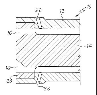
invention, comprises an ingot mold indicated by 10 in Figure 2,
formed by an external body or envelope 12 and a coaxial pin 14
from graphite or other suitable materials. Said ingot mold 10 is
provided with conventional axial holes 16 for the feeding of the
molten metal, fed by a crucible 18, schematized in Figure l,
obtained from refractory material, graphite or masonry.
Holes 16 are formed on a support or bridge 20 that supports pin
14. In addition to said holes 16, the ingot mold 10 is
advantageously provided with further radial feeding holes 22, for
instance in number of 4, arranged at 90°, formed on the external
body 12 downstream of bride 20. Holes 22, by way of example
inclined, communicate with holes 16 and allow to feed the ingot
mold 10 with an additional amount of~ molten metal that mixes
suitably and remains at the stable temperature required to form
the preform.
The homogenization of the metal, thanks to the additional
feeding through holes 22, is of basic importance in those cases,
CA 02400767 2002-08-20
WO 01/64372 I2 PCT/EP01/01569
as is the present one, of alloys whose components have dif~'erent
melting points and physical-chemical characteristics.
According to a further and advantageous characteristic, the
apparatus of the present invention keeps constant the weight
generated by the metallostatic load in the feeding zone of the
ingot mold 10, also during the variations in the liquid that take
place in crucible I8. For this purpose, crucible 18 is provided
with a bell 26 inserted centrally in said crucible and tied to it with
known means. The upper front 28 of said bell 26 is constituted of
a tight-lid. To said lid 28 a tube or duct 40 is connected through
which there is for instance inserted a neutral gas in bell 26. Said
bell 26 forms, in the inside of crucible 18, a central chamber 30,
wherein a pressure preferably comprised between 0 and 2 bar is
applied to the free surface of the molten metal.
In Figure I the level of molten metal existing in the inside
respectively the outside of the central chamber 30 are indicated
by L I and L2. By means of such pressure with inert gas, the
liquid state metal is fed in a constant and homogeneous manner
to the ingot mold I O through holes I6, 22 of the same, and is not
affected by the level variations.
The apparatus of the present invention also comprises cold
rolling mills and draw-benches to reduce progressively the
CA 02400767 2006-05-17
13
section of the preform up to the size desired. During the drawing
step or between a rolling mill step and a drawing step, the
preform may be submitted to thermal treatments, such as for
instance annealing. The so obtained section bar may be submitted
to straightening, degreasing treatments and the like, and then cut
to measure.
~s can be understood from the above description, the advantages
achieved by the invention are evident:
V'ith the process for the realization of metal tubes or section bars
of the present invention, the length and complexity of the
production cycle reduce substantially, being possible to obtain
the preform from melting instead of drawing. In the same way
the workin, scraps and plant requirements reduce to a substantial
extent, no casting being needed to obtain the billets and the
draw-press.
In another aspect, the invention provides a process for the
manufacture of tubes or section bars for industrial use from a
metal material including copper, copper alloys, cupronickel,
brasses or aluminium bronze by cold working a continuously cast
hollow tubular preform having a diameter of between 70 and 80
mm and a thickness of between 5 and 10 mm, thereby reducing
the initial section thereof, the cold work reduction of the hollow
tubular preform being carried out by roll milling or drawing or by
a combination of roll milling and drawing, further reducing the
CA 02400767 2006-05-17
13a
section of the roll milled and/or drawn preform to desired final
dimensions by drawing operations, and straightening and
optionally submitting to thermal and/or degreasing treatments)
the dimensionally finished tube or section bar, and cutting the
tube or section bar to measure, wherein the hollow tubular
preform is produced by direct and continuous casting of the metal
material, optionally in mixture with scraps thereof, molten at a
temperature comprised between 900 and 1350°C, by feeding both
the molten metal material and scraps thereof through axial holes
of a horizontal type ingot mould and an additional amount of the
molten material through radial feeding holes communicating with
the axial holes, and wherein the rolling mill operations) and the
drawing operations) are carried out by cold draw-benches.
In another aspect, the invention provides an apparatus for
continuous casting of a molten copper alloy to obtain a hollow
tubular preform for the production of a metallic product, in the
form of a tube or section bar, for industrial use from a copper
alloy, the apparatus comprising a crucible, and an ingot mold
connected to the crucible and including, an external body, a pin
coaxial and internal to the external body, a bridge supporting the
pin, a plurality of axial feeding holes formed on the bridge and
feeding the molten alloy from the crucible, and at least one radial
feeding hole communicating with a first axial feeding hole of the
plurality of axial feeding holes, and feeding an additional amount
CA 02400767 2006-05-17
13b
of the molten alloy from the crucible to the first axial feeding hole
wherein the at least one radial feeding hole is positioned on the
external body of the ingot mold downstream of the bridge.
~Vlule the present invention has been described above with
reference to an embodiment of the same, solely reported by way
of non limiting example, various modifications and chances will
be evident to those skilled in the art. in the light of the above
description. Therefore, the present invention encompasses all the
modifications and variants that fall within the spirit and scope of
the following claims.