Language selection

Search

Patent 2401154 Summary

Third-party information liability

Some of the information on this Web page has been provided by external sources. The Government of Canada is not responsible for the accuracy, reliability or currency of the information supplied by external sources. Users wishing to rely upon this information should consult directly with the source of the information. Content provided by external sources is not subject to official languages, privacy and accessibility requirements.

Claims and Abstract availability

Any discrepancies in the text and image of the Claims and Abstract are due to differing posting times. Text of the Claims and Abstract are posted:

  • At the time the application is open to public inspection;
  • At the time of issue of the patent (grant).
(12) Patent Application: (11) CA 2401154
(54) English Title: FIRE SAFE CLOSURE RING SEAL SYSTEM FOR FLUG VALVES
(54) French Title: SYSTEME DE BAGUE DE FERMETURE ANTI-FEU POUR CLAPETS D'OBTURATION
Status: Deemed Abandoned and Beyond the Period of Reinstatement - Pending Response to Notice of Disregarded Communication
Bibliographic Data
(51) International Patent Classification (IPC):
  • F16K 5/02 (2006.01)
  • F16K 5/04 (2006.01)
  • F16K 5/06 (2006.01)
  • F16K 27/06 (2006.01)
(72) Inventors :
  • SMITH, GORDON M. (United States of America)
  • HOTZ, JOHN A. (United States of America)
  • KNIGHT, COLIN G. (United States of America)
  • CONLEY, JEFFREY R. (United States of America)
  • KRUPALA, GENE T. (United States of America)
(73) Owners :
  • GENERAL VALVE, INC.
(71) Applicants :
  • GENERAL VALVE, INC. (United States of America)
(74) Agent: KIRBY EADES GALE BAKER
(74) Associate agent:
(45) Issued:
(86) PCT Filing Date: 2001-02-23
(87) Open to Public Inspection: 2001-09-07
Availability of licence: N/A
Dedicated to the Public: N/A
(25) Language of filing: English

Patent Cooperation Treaty (PCT): Yes
(86) PCT Filing Number: PCT/US2001/005749
(87) International Publication Number: WO 2001065156
(85) National Entry: 2002-08-22

(30) Application Priority Data:
Application No. Country/Territory Date
09/513,875 (United States of America) 2000-02-28

Abstracts

English Abstract


a seal system comprises a non-flat cross-section, fire resistant compressible
ring (44) and an annular pocket (42) formed between two engagting surfaces
(36, 38) of a pressure vessel such as a plug valve (10). The pocket is formed
by providing a chamfer (40) in one such surface (38) which is then enclosed by
the other such surface (36). The ring is compressed within the pocket to
substantially fill the pocket upon mating of the two surfaces.


French Abstract

L'invention concerne un système d'étanchéité comprenant une bague compressible résistant au feu, de section transversale non plane, et une poche annulaire constituée entre deux surfaces en prise d'un récipient à pression, par exemple un clapet d'obturation. La poche est réalisée par chanfreinage d'une de ces surfaces, laquelle surface se trouve alors incorporée dans l'autre. La bague est comprimée à l'intérieur de la poche de façon à remplir sensiblement cette dernière lorsque les deux surfaces s'épousent.

Claims

Note: Claims are shown in the official language in which they were submitted.

8
CLAIMS
1. A plug valve (10) having a body (12) containing a rotatable plug (14), the
plug
having a passage (16) for selective alignment with connecting inlet and outlet
pipes,
the body being enclosed by a bonnet (30) and a bottom cover (28) to form a
sealed
chamber within said body, said bonnet having a flange (36) engaging a top
surface
(38) of said body and having a fire seal (44) therebetween, wherein said seal
comprises a non-flat compressible heat resistant ring, said ring being located
in a
chamfered region (40) of said top surface of said body, said chamfered region
forming an annular pocket (42) shaped to receive said ring.
2. A plug valve according to claim 1, wherein said ring has a trapezoidal
cross-
section.
3. A plug valve according to claim 1 or 2, wherein said ring has are
uncompressed length which exceeds the depth of said pocket.
4. A plug valve according to claim 1, 2 or 3, wherein said ring has a size and
cross-section for compressibly filling said annular pocket upon attachment of
said
bonnet to said body.

9
5. A plug valve according to any one of the preceding claims wherein said ring
has a size and shape for applying sealing forces in two orthogonal directions
upon
attachment of said bonnet to said body.
6. A fire seal apparatus for use in an enclosed vessel containing a fluid
under
pressure, the vessel having at least two mating surfaces which at least
partially
overlap at a junction to define an annular pocket (42) formed by a chamfer
(40) in
one of the mating surfaces, said fire seal apparatus comprising a heat
resistant
compressible ring (44) wherein said ring has a non-flat cross-section and is
positioned within said annular pocket (42), the arrangement being such that
the
other of said mating surfaces compresses said ring into said pocket.
7. A fire seal apparatus according to claim 6, wherein said ring has a
trapezoidal
cross-section.
8. A fire seal apparatus according to claim 6 or 7, wherein said ring has an
uncompressed length which exceeds the depth of said pocket.

10
9. A fire seal apparatus according to any one of claims 6, 7 or 8, wherein
said
ring has a size and cross-section for compressibly filling said annular pocket
upon
attachment of said bonnet to said body.
10. A fire seal apparatus according to any one of claims 6-9, wherein said
ring
has a size and shape for applying sealing forces in two orthogonal directions
upon
attachment of said bonnet to said body.

Description

Note: Descriptions are shown in the official language in which they were submitted.


CA 02401154 2002-08-22
WO 01/65156 PCT/USO1/05749
FIRE SAFE CLOSURE RING SEAL SYSTEM FOR PLUG VALVES
FIELD OF THE INVENTION
The present invention relates generally to plug valves and more particularly
to a
fire safe closure seal ring system which replaces the conventional gasket and
permits smaller bolting, smaller bonnets and increased effectiveness and
dependability.

CA 02401154 2002-08-22
WO 01/65156 PCT/USO1/05749
2
BACKGROUND ART
The current state of the art in fire safety for plug valves consists of
graphite
gaskets and packing rings. The prior art consists of asbestos and graphite
materials which are sufficiently compliant in response to compressive loads to
effect
a seal which is sufficiently sturdy to support pressure and mechanical loads.
These
materials are also sufficient to withstand fire temperatures higher than 1400
degrees
Fahrenheit. They are also resistant to most chemical substances.
Conventional gaskets for plug valves tend to be flat and wide. For example, in
one
typical embodiment of prior art plug valves, a circular gasket has a thickness
of .030
inches and a width of 3/8 to 3/4 inches. The gasket is deployed outwardly from
the
valve body bore ID to the inboard side of the body closure bolts thereby
requiring
the body to have a flat, polished circular area for installation. The body
closure
bolts are required to maintain pressure vessel integrity despite hydrostatic
loads,
valve operator thrust and the gasket sealing load which is not insubstantial.
It would
be highly advantageous if the flat graphite gasket of the prior art could be
replaced
by a seal which is more effective and requires lower degrees of bolt loading.

CA 02401154 2002-08-22
WO 01/65156 PCT/USO1/05749
3
SUMMARY OF THE INVENTION
The fire seal of the present invention replaces the prior art gasket with a
compact
fire safe ring seal. The seat of the present invention differs from the prior
art gasket
in two principal ways. First, the seal is shaped differently. Unlike the prior
art
gasket, the inventive seal is not flat. It is preferably round, square,
triangular,
trapezoidal or other non-flat cross-section so that it effects the seal with
less bolt
loading. Second, the seal is located in a more outboard chamfered region of
the
body flange that is trapped against the adjacent closure flange. Because it is
thicker, the seal is more compliant. The compliance combined with the chamfer
configuration, yield significant sealing effectiveness without the same degree
of bolt
loading. Lower bolt loading permits use of smaller components. The body flange
can be smaller and the closure flange can be thinner. The result is a lighter
and
lower cost valve structure. In addition, the bolts can be smaller which also
reduces
weight and costs.

CA 02401154 2002-08-22
WO 01/65156 PCT/USO1/05749
4
OBJECTS OF THE INVENTION
It is therefore a principal object of the present invention to provide a fire
safe ring
seal system for plug valves and which results in lighter and lower cost
structures.
It is another object of the invention to provide an improved plug valve which
has a
non-flat fire safe ring seal and chamfered seal pocket implementation for
reducing
bolt loading.
It is still an additional object of the invention to reduce body flange,
closure flange
and bolting size and weight in plug-type valves by providing a more effective
fire
safe seal and locating the seal in a more effective location on the valve.
It is still another object of the invention to provide an improved fire-safe
ring seal
system for vessels designed to contain fluids under pressure.

CA 02401154 2002-08-22
WO 01/65156 PCT/USO1/05749
BRIEF DESCRIPTION OF THE DRAWINGS
The aforementioned objects and advantages of the present invention, as well as
additional objects and advantages thereof, will be more fully understood
hereinafter
as a result of a detailed description of a preferred embodiment when taken in
conjunction with the following drawings in which:
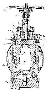
FIG. 1 is a cross-sectional view of a plug valve implemented with a fire safe
ring
seal system in accordance with a preferred embodiment of the invention;
FIG. 2 is an enlarged view of the portion of the plug valve labeled "see FIG.
2" in
FIG. 1 with a bolt omitted for visual advantage;
FiG. 3 is a three-dimensional view of a ring seal used in fibs preferred
embodiment
of FIG. 1
FIG. 4 is an elevational view of the ring seal of FIG. 3;
FIG. 5 is a side view of the ring seal;
FIG. 6 is an enlarged view of the portion of the ring seal labeled "see F1G.
6" in
FIG. 5.

CA 02401154 2002-08-22
WO 01/65156 PCT/USO1/05749
6
DETAILED DESCRIPTION OF A PREFERRED EMBODIMENT
Referring now to the accompanying figures and FIGs. 1 and 2 in particular, it
will
be seen that a plug valve 10 comprises a body 12 enclosing a rotatable plug 14
having a flow passage 16. The valve is shown in the open configuration with
the
flow passage 16 aligned with connecting pipes (not shown) secured to the valve
10
by connecting flanges 18. Plug 14 has a pair of slips 15 affixed on opposing
sides
of the plug to stop flow when the plug is rotated 90 degrees to place flow
passage
16 in a direction perpendicular to that shown in FIG. 1. The plug is integral
to an
upper trunnion 20 and a lower trunnion 26. Upper trunnion 20 is controlled by
an
operator 22 and a handle 24 to position plug 14 in either the opened or closed
position.
This form of plug valve is referred to as a double block and bleed valve
because it
permits the fluid in the valve body to be bled out when the slips seal against
both
the inlet and the outlet ports'. However, it will be understood that the fire
ring seal
system disclosed herein is not limited to such valves and maybe used
advantageously in any valve, pump or other structure where fire safe sealing
of an
enclosed, pressurized fluid is desirable. A bottom cover 28 is secured to the
lower
end of body 12 by bolts 29. The upper end of body 12 is enclosed by a bonnet
30
secured by a bolt ring 32 and bolts 34.
Bonnet 30 has a flange 36 which is in contact with the upper surface 38 of
body
12. As seen best in FIG. 2, the upper surface 38 has a chamfer 40 to form an
annular pocket 42 which receives the fire ring seal 44 of the present
invention.
Below chamfer 40 there is an O-ring 46 mounted in the main portion of the
bonnet
30. As seen best in FIGs. 3-6, fire ring seal 44 is circular and has a
trapezoidal
cross-section with one axial end of the circular seal being thicker than the
other
axial end. The thicker axial end is positioned at the upper edge of chamfer 40
and
as seen in FIG. 2, is in direct compressive contact with flange 36 of the
bonnet 30.

CA 02401154 2002-08-22
WO 01/65156 PCT/USO1/05749
7
The fire ring seal 44 is preferably a GRAFOIL~ ring available from Union
Carbide
Company of New York City. Because of the unique chamfer configuration for
positioning ring seal 44, the seal is more compliant and is subjected to both
lateral
and longitudinal compression to effect fire safe sealing. The shape and
dimensions
of the ring seal 44 relative to the shape and dimensions of pocket 42 permit
effective
sealing with less bolt loading from bolts 34. More particularly, the axial
length of
ring seal 44 (A + B in FIG. 6) is preferably greater than the depth of chamfer
40
along the axial direction of plug 14 by the length B (of FIG. 6) and the
thickness C of
ring seal 44 is preferably about the same as the widfih of chamfer 40 along
the radial
direction of plug 14. These relative dimensions of ring seal 44 and pocket 42,
assure that the ring seal overfills the chamfer pocket prior to connection of
the
bonnet 30 to body 12. Moreover, it assures excellent sealing with the
tightening of
bolts 34 to a loading level well below that required with the flat gasket
sealing of the
prior art. This permits the use of smaller bolts. Moreover, lower bolt.loading
requirements also permit a reduction in the size of body surtace 38, a
reduction in
the size of bonnet flange 36 and thus a lighter and lower cost plug valve
which still
meets all fire safety regulatory specifications.
Having thus disclosed a preferred embodiment of the invention, it being
understood that many alternative shapes, sizes and locations are contemplated
for
the ring seal and chamfer chamber, what is claimed is:

Representative Drawing
A single figure which represents the drawing illustrating the invention.
Administrative Status

2024-08-01:As part of the Next Generation Patents (NGP) transition, the Canadian Patents Database (CPD) now contains a more detailed Event History, which replicates the Event Log of our new back-office solution.

Please note that "Inactive:" events refers to events no longer in use in our new back-office solution.

For a clearer understanding of the status of the application/patent presented on this page, the site Disclaimer , as well as the definitions for Patent , Event History , Maintenance Fee  and Payment History  should be consulted.

Event History

Description Date
Inactive: IPC from MCD 2006-03-12
Application Not Reinstated by Deadline 2004-02-23
Time Limit for Reversal Expired 2004-02-23
Inactive: Status info is complete as of Log entry date 2004-01-07
Inactive: Abandoned - No reply to Office letter 2003-11-25
Deemed Abandoned - Failure to Respond to Maintenance Fee Notice 2003-02-24
Inactive: Courtesy letter - Evidence 2002-12-10
Inactive: Cover page published 2002-12-06
Inactive: Notice - National entry - No RFE 2002-12-03
Application Received - PCT 2002-10-10
National Entry Requirements Determined Compliant 2002-08-22
Application Published (Open to Public Inspection) 2001-09-07

Abandonment History

Abandonment Date Reason Reinstatement Date
2003-02-24

Fee History

Fee Type Anniversary Year Due Date Paid Date
Basic national fee - standard 2002-08-22
Owners on Record

Note: Records showing the ownership history in alphabetical order.

Current Owners on Record
GENERAL VALVE, INC.
Past Owners on Record
COLIN G. KNIGHT
GENE T. KRUPALA
GORDON M. SMITH
JEFFREY R. CONLEY
JOHN A. HOTZ
Past Owners that do not appear in the "Owners on Record" listing will appear in other documentation within the application.
Documents

To view selected files, please enter reCAPTCHA code :


To view images, click a link in the Document Description column. To download the documents, select one or more checkboxes in the first column and then click the "Download Selected in PDF format (Zip Archive)" or the "Download Selected as Single PDF" button.

List of published and non-published patent-specific documents on the CPD .

If you have any difficulty accessing content, you can call the Client Service Centre at 1-866-997-1936 or send them an e-mail at CIPO Client Service Centre.


Document
Description 
Date
(yyyy-mm-dd) 
Number of pages   Size of Image (KB) 
Representative drawing 2002-12-05 1 16
Cover Page 2002-12-06 2 51
Abstract 2002-08-22 2 66
Description 2002-08-22 7 210
Drawings 2002-08-22 3 73
Claims 2002-08-22 3 68
Reminder of maintenance fee due 2002-12-03 1 106
Notice of National Entry 2002-12-03 1 189
Courtesy - Abandonment Letter (Maintenance Fee) 2003-03-24 1 179
Request for evidence or missing transfer 2003-08-25 1 102
Courtesy - Abandonment Letter (Office letter) 2003-12-30 1 167
PCT 2002-08-22 3 92
Correspondence 2002-12-03 1 23
PCT 2002-08-23 4 168