Sélection de la langue

Search

Sommaire du brevet 2401154 

Énoncé de désistement de responsabilité concernant l'information provenant de tiers

Une partie des informations de ce site Web a été fournie par des sources externes. Le gouvernement du Canada n'assume aucune responsabilité concernant la précision, l'actualité ou la fiabilité des informations fournies par les sources externes. Les utilisateurs qui désirent employer cette information devraient consulter directement la source des informations. Le contenu fourni par les sources externes n'est pas assujetti aux exigences sur les langues officielles, la protection des renseignements personnels et l'accessibilité.

Disponibilité de l'Abrégé et des Revendications

L'apparition de différences dans le texte et l'image des Revendications et de l'Abrégé dépend du moment auquel le document est publié. Les textes des Revendications et de l'Abrégé sont affichés :

  • lorsque la demande peut être examinée par le public;
  • lorsque le brevet est émis (délivrance).
(12) Demande de brevet: (11) CA 2401154
(54) Titre français: SYSTEME DE BAGUE DE FERMETURE ANTI-FEU POUR CLAPETS D'OBTURATION
(54) Titre anglais: FIRE SAFE CLOSURE RING SEAL SYSTEM FOR FLUG VALVES
Statut: Réputée abandonnée et au-delà du délai pour le rétablissement - en attente de la réponse à l’avis de communication rejetée
Données bibliographiques
(51) Classification internationale des brevets (CIB):
  • F16K 5/02 (2006.01)
  • F16K 5/04 (2006.01)
  • F16K 5/06 (2006.01)
  • F16K 27/06 (2006.01)
(72) Inventeurs :
  • SMITH, GORDON M. (Etats-Unis d'Amérique)
  • HOTZ, JOHN A. (Etats-Unis d'Amérique)
  • KNIGHT, COLIN G. (Etats-Unis d'Amérique)
  • CONLEY, JEFFREY R. (Etats-Unis d'Amérique)
  • KRUPALA, GENE T. (Etats-Unis d'Amérique)
(73) Titulaires :
  • GENERAL VALVE, INC.
(71) Demandeurs :
  • GENERAL VALVE, INC. (Etats-Unis d'Amérique)
(74) Agent: KIRBY EADES GALE BAKER
(74) Co-agent:
(45) Délivré:
(86) Date de dépôt PCT: 2001-02-23
(87) Mise à la disponibilité du public: 2001-09-07
Licence disponible: S.O.
Cédé au domaine public: S.O.
(25) Langue des documents déposés: Anglais

Traité de coopération en matière de brevets (PCT): Oui
(86) Numéro de la demande PCT: PCT/US2001/005749
(87) Numéro de publication internationale PCT: WO 2001065156
(85) Entrée nationale: 2002-08-22

(30) Données de priorité de la demande:
Numéro de la demande Pays / territoire Date
09/513,875 (Etats-Unis d'Amérique) 2000-02-28

Abrégés

Abrégé français

L'invention concerne un système d'étanchéité comprenant une bague compressible résistant au feu, de section transversale non plane, et une poche annulaire constituée entre deux surfaces en prise d'un récipient à pression, par exemple un clapet d'obturation. La poche est réalisée par chanfreinage d'une de ces surfaces, laquelle surface se trouve alors incorporée dans l'autre. La bague est comprimée à l'intérieur de la poche de façon à remplir sensiblement cette dernière lorsque les deux surfaces s'épousent.


Abrégé anglais


a seal system comprises a non-flat cross-section, fire resistant compressible
ring (44) and an annular pocket (42) formed between two engagting surfaces
(36, 38) of a pressure vessel such as a plug valve (10). The pocket is formed
by providing a chamfer (40) in one such surface (38) which is then enclosed by
the other such surface (36). The ring is compressed within the pocket to
substantially fill the pocket upon mating of the two surfaces.

Revendications

Note : Les revendications sont présentées dans la langue officielle dans laquelle elles ont été soumises.


8
CLAIMS
1. A plug valve (10) having a body (12) containing a rotatable plug (14), the
plug
having a passage (16) for selective alignment with connecting inlet and outlet
pipes,
the body being enclosed by a bonnet (30) and a bottom cover (28) to form a
sealed
chamber within said body, said bonnet having a flange (36) engaging a top
surface
(38) of said body and having a fire seal (44) therebetween, wherein said seal
comprises a non-flat compressible heat resistant ring, said ring being located
in a
chamfered region (40) of said top surface of said body, said chamfered region
forming an annular pocket (42) shaped to receive said ring.
2. A plug valve according to claim 1, wherein said ring has a trapezoidal
cross-
section.
3. A plug valve according to claim 1 or 2, wherein said ring has are
uncompressed length which exceeds the depth of said pocket.
4. A plug valve according to claim 1, 2 or 3, wherein said ring has a size and
cross-section for compressibly filling said annular pocket upon attachment of
said
bonnet to said body.

9
5. A plug valve according to any one of the preceding claims wherein said ring
has a size and shape for applying sealing forces in two orthogonal directions
upon
attachment of said bonnet to said body.
6. A fire seal apparatus for use in an enclosed vessel containing a fluid
under
pressure, the vessel having at least two mating surfaces which at least
partially
overlap at a junction to define an annular pocket (42) formed by a chamfer
(40) in
one of the mating surfaces, said fire seal apparatus comprising a heat
resistant
compressible ring (44) wherein said ring has a non-flat cross-section and is
positioned within said annular pocket (42), the arrangement being such that
the
other of said mating surfaces compresses said ring into said pocket.
7. A fire seal apparatus according to claim 6, wherein said ring has a
trapezoidal
cross-section.
8. A fire seal apparatus according to claim 6 or 7, wherein said ring has an
uncompressed length which exceeds the depth of said pocket.

10
9. A fire seal apparatus according to any one of claims 6, 7 or 8, wherein
said
ring has a size and cross-section for compressibly filling said annular pocket
upon
attachment of said bonnet to said body.
10. A fire seal apparatus according to any one of claims 6-9, wherein said
ring
has a size and shape for applying sealing forces in two orthogonal directions
upon
attachment of said bonnet to said body.

Description

Note : Les descriptions sont présentées dans la langue officielle dans laquelle elles ont été soumises.

CA 02401154 2002-08-22
WO 01/65156 PCT/USO1/05749
FIRE SAFE CLOSURE RING SEAL SYSTEM FOR PLUG VALVES
FIELD OF THE INVENTION
The present invention relates generally to plug valves and more particularly
to a
fire safe closure seal ring system which replaces the conventional gasket and
permits smaller bolting, smaller bonnets and increased effectiveness and
dependability.

CA 02401154 2002-08-22
WO 01/65156 PCT/USO1/05749
2
BACKGROUND ART
The current state of the art in fire safety for plug valves consists of
graphite
gaskets and packing rings. The prior art consists of asbestos and graphite
materials which are sufficiently compliant in response to compressive loads to
effect
a seal which is sufficiently sturdy to support pressure and mechanical loads.
These
materials are also sufficient to withstand fire temperatures higher than 1400
degrees
Fahrenheit. They are also resistant to most chemical substances.
Conventional gaskets for plug valves tend to be flat and wide. For example, in
one
typical embodiment of prior art plug valves, a circular gasket has a thickness
of .030
inches and a width of 3/8 to 3/4 inches. The gasket is deployed outwardly from
the
valve body bore ID to the inboard side of the body closure bolts thereby
requiring
the body to have a flat, polished circular area for installation. The body
closure
bolts are required to maintain pressure vessel integrity despite hydrostatic
loads,
valve operator thrust and the gasket sealing load which is not insubstantial.
It would
be highly advantageous if the flat graphite gasket of the prior art could be
replaced
by a seal which is more effective and requires lower degrees of bolt loading.

CA 02401154 2002-08-22
WO 01/65156 PCT/USO1/05749
3
SUMMARY OF THE INVENTION
The fire seal of the present invention replaces the prior art gasket with a
compact
fire safe ring seal. The seat of the present invention differs from the prior
art gasket
in two principal ways. First, the seal is shaped differently. Unlike the prior
art
gasket, the inventive seal is not flat. It is preferably round, square,
triangular,
trapezoidal or other non-flat cross-section so that it effects the seal with
less bolt
loading. Second, the seal is located in a more outboard chamfered region of
the
body flange that is trapped against the adjacent closure flange. Because it is
thicker, the seal is more compliant. The compliance combined with the chamfer
configuration, yield significant sealing effectiveness without the same degree
of bolt
loading. Lower bolt loading permits use of smaller components. The body flange
can be smaller and the closure flange can be thinner. The result is a lighter
and
lower cost valve structure. In addition, the bolts can be smaller which also
reduces
weight and costs.

CA 02401154 2002-08-22
WO 01/65156 PCT/USO1/05749
4
OBJECTS OF THE INVENTION
It is therefore a principal object of the present invention to provide a fire
safe ring
seal system for plug valves and which results in lighter and lower cost
structures.
It is another object of the invention to provide an improved plug valve which
has a
non-flat fire safe ring seal and chamfered seal pocket implementation for
reducing
bolt loading.
It is still an additional object of the invention to reduce body flange,
closure flange
and bolting size and weight in plug-type valves by providing a more effective
fire
safe seal and locating the seal in a more effective location on the valve.
It is still another object of the invention to provide an improved fire-safe
ring seal
system for vessels designed to contain fluids under pressure.

CA 02401154 2002-08-22
WO 01/65156 PCT/USO1/05749
BRIEF DESCRIPTION OF THE DRAWINGS
The aforementioned objects and advantages of the present invention, as well as
additional objects and advantages thereof, will be more fully understood
hereinafter
as a result of a detailed description of a preferred embodiment when taken in
conjunction with the following drawings in which:
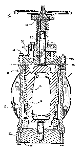
FIG. 1 is a cross-sectional view of a plug valve implemented with a fire safe
ring
seal system in accordance with a preferred embodiment of the invention;
FIG. 2 is an enlarged view of the portion of the plug valve labeled "see FIG.
2" in
FIG. 1 with a bolt omitted for visual advantage;
FiG. 3 is a three-dimensional view of a ring seal used in fibs preferred
embodiment
of FIG. 1
FIG. 4 is an elevational view of the ring seal of FIG. 3;
FIG. 5 is a side view of the ring seal;
FIG. 6 is an enlarged view of the portion of the ring seal labeled "see F1G.
6" in
FIG. 5.

CA 02401154 2002-08-22
WO 01/65156 PCT/USO1/05749
6
DETAILED DESCRIPTION OF A PREFERRED EMBODIMENT
Referring now to the accompanying figures and FIGs. 1 and 2 in particular, it
will
be seen that a plug valve 10 comprises a body 12 enclosing a rotatable plug 14
having a flow passage 16. The valve is shown in the open configuration with
the
flow passage 16 aligned with connecting pipes (not shown) secured to the valve
10
by connecting flanges 18. Plug 14 has a pair of slips 15 affixed on opposing
sides
of the plug to stop flow when the plug is rotated 90 degrees to place flow
passage
16 in a direction perpendicular to that shown in FIG. 1. The plug is integral
to an
upper trunnion 20 and a lower trunnion 26. Upper trunnion 20 is controlled by
an
operator 22 and a handle 24 to position plug 14 in either the opened or closed
position.
This form of plug valve is referred to as a double block and bleed valve
because it
permits the fluid in the valve body to be bled out when the slips seal against
both
the inlet and the outlet ports'. However, it will be understood that the fire
ring seal
system disclosed herein is not limited to such valves and maybe used
advantageously in any valve, pump or other structure where fire safe sealing
of an
enclosed, pressurized fluid is desirable. A bottom cover 28 is secured to the
lower
end of body 12 by bolts 29. The upper end of body 12 is enclosed by a bonnet
30
secured by a bolt ring 32 and bolts 34.
Bonnet 30 has a flange 36 which is in contact with the upper surface 38 of
body
12. As seen best in FIG. 2, the upper surface 38 has a chamfer 40 to form an
annular pocket 42 which receives the fire ring seal 44 of the present
invention.
Below chamfer 40 there is an O-ring 46 mounted in the main portion of the
bonnet
30. As seen best in FIGs. 3-6, fire ring seal 44 is circular and has a
trapezoidal
cross-section with one axial end of the circular seal being thicker than the
other
axial end. The thicker axial end is positioned at the upper edge of chamfer 40
and
as seen in FIG. 2, is in direct compressive contact with flange 36 of the
bonnet 30.

CA 02401154 2002-08-22
WO 01/65156 PCT/USO1/05749
7
The fire ring seal 44 is preferably a GRAFOIL~ ring available from Union
Carbide
Company of New York City. Because of the unique chamfer configuration for
positioning ring seal 44, the seal is more compliant and is subjected to both
lateral
and longitudinal compression to effect fire safe sealing. The shape and
dimensions
of the ring seal 44 relative to the shape and dimensions of pocket 42 permit
effective
sealing with less bolt loading from bolts 34. More particularly, the axial
length of
ring seal 44 (A + B in FIG. 6) is preferably greater than the depth of chamfer
40
along the axial direction of plug 14 by the length B (of FIG. 6) and the
thickness C of
ring seal 44 is preferably about the same as the widfih of chamfer 40 along
the radial
direction of plug 14. These relative dimensions of ring seal 44 and pocket 42,
assure that the ring seal overfills the chamfer pocket prior to connection of
the
bonnet 30 to body 12. Moreover, it assures excellent sealing with the
tightening of
bolts 34 to a loading level well below that required with the flat gasket
sealing of the
prior art. This permits the use of smaller bolts. Moreover, lower bolt.loading
requirements also permit a reduction in the size of body surtace 38, a
reduction in
the size of bonnet flange 36 and thus a lighter and lower cost plug valve
which still
meets all fire safety regulatory specifications.
Having thus disclosed a preferred embodiment of the invention, it being
understood that many alternative shapes, sizes and locations are contemplated
for
the ring seal and chamfer chamber, what is claimed is:

Dessin représentatif
Une figure unique qui représente un dessin illustrant l'invention.
États administratifs

2024-08-01 : Dans le cadre de la transition vers les Brevets de nouvelle génération (BNG), la base de données sur les brevets canadiens (BDBC) contient désormais un Historique d'événement plus détaillé, qui reproduit le Journal des événements de notre nouvelle solution interne.

Veuillez noter que les événements débutant par « Inactive : » se réfèrent à des événements qui ne sont plus utilisés dans notre nouvelle solution interne.

Pour une meilleure compréhension de l'état de la demande ou brevet qui figure sur cette page, la rubrique Mise en garde , et les descriptions de Brevet , Historique d'événement , Taxes périodiques et Historique des paiements devraient être consultées.

Historique d'événement

Description Date
Inactive : CIB de MCD 2006-03-12
Demande non rétablie avant l'échéance 2004-02-23
Le délai pour l'annulation est expiré 2004-02-23
Inactive : Renseign. sur l'état - Complets dès date d'ent. journ. 2004-01-07
Inactive : Abandon. - Aucune rép. à lettre officielle 2003-11-25
Réputée abandonnée - omission de répondre à un avis sur les taxes pour le maintien en état 2003-02-24
Inactive : Lettre de courtoisie - Preuve 2002-12-10
Inactive : Page couverture publiée 2002-12-06
Inactive : Notice - Entrée phase nat. - Pas de RE 2002-12-03
Demande reçue - PCT 2002-10-10
Exigences pour l'entrée dans la phase nationale - jugée conforme 2002-08-22
Demande publiée (accessible au public) 2001-09-07

Historique d'abandonnement

Date d'abandonnement Raison Date de rétablissement
2003-02-24

Historique des taxes

Type de taxes Anniversaire Échéance Date payée
Taxe nationale de base - générale 2002-08-22
Titulaires au dossier

Les titulaires actuels et antérieures au dossier sont affichés en ordre alphabétique.

Titulaires actuels au dossier
GENERAL VALVE, INC.
Titulaires antérieures au dossier
COLIN G. KNIGHT
GENE T. KRUPALA
GORDON M. SMITH
JEFFREY R. CONLEY
JOHN A. HOTZ
Les propriétaires antérieurs qui ne figurent pas dans la liste des « Propriétaires au dossier » apparaîtront dans d'autres documents au dossier.
Documents

Pour visionner les fichiers sélectionnés, entrer le code reCAPTCHA :


Pour visualiser une image, cliquer sur un lien dans la colonne description du document. Pour télécharger l'image (les images), cliquer l'une ou plusieurs cases à cocher dans la première colonne et ensuite cliquer sur le bouton "Télécharger sélection en format PDF (archive Zip)" ou le bouton "Télécharger sélection (en un fichier PDF fusionné)".

Liste des documents de brevet publiés et non publiés sur la BDBC .

Si vous avez des difficultés à accéder au contenu, veuillez communiquer avec le Centre de services à la clientèle au 1-866-997-1936, ou envoyer un courriel au Centre de service à la clientèle de l'OPIC.


Description du
Document 
Date
(aaaa-mm-jj) 
Nombre de pages   Taille de l'image (Ko) 
Dessin représentatif 2002-12-05 1 16
Page couverture 2002-12-06 2 51
Abrégé 2002-08-22 2 66
Description 2002-08-22 7 210
Dessins 2002-08-22 3 73
Revendications 2002-08-22 3 68
Rappel de taxe de maintien due 2002-12-03 1 106
Avis d'entree dans la phase nationale 2002-12-03 1 189
Courtoisie - Lettre d'abandon (taxe de maintien en état) 2003-03-24 1 179
Demande de preuve ou de transfert manquant 2003-08-25 1 102
Courtoisie - Lettre d'abandon (lettre du bureau) 2003-12-30 1 167
PCT 2002-08-22 3 92
Correspondance 2002-12-03 1 23
PCT 2002-08-23 4 168