Note: Descriptions are shown in the official language in which they were submitted.
CA 02401208 2002-08-26
- 1
DESCRIPTiON
UNIT SET FOR ROBOT
Technical Field
The present invention relates to a unit set for a robot, consisting of
multiple types of units
which are freely connected one with another to configure a robot, and
particularly relates to a
unit set far a robot including robot joint units for realizing the functions
of joints by perForming
rotational driving of a rotating joint means facing outwards by means of a
rotation driving means
such as a built-in motor or the like, thereby rotationally driving other
external components
detachably connected to the rotating joint means.
Background Art
Various types of such robot joint units have already been realized, with one
typical
example being disclosed in Japanese Examined Patent Application Publication
No. 63-50155.
According to this typical example, as shown in Fig. 20, a joint unit 1 is
configured with an output
rotating shaft 1 c of a motor 1 b built into a reducing device assembled
inside an inner casing 1a,
being connected to the inner face of an outer casing 1c via a coupling
mechanism 1d, and with
an outer casing center portion arm attaching portion 1f being fixed on the
outer surface of the
outer casing 1 a along the output rotating shaft 1 c so as to rotate around
the output rotating shaft
1 c, wherein the perimeter portion of the outer casing 1 a encloses the
portion of the inner casing
1a shown at the lower side in the diagram so as to be relatively rotationally
drivable, and
wherein an outer casing perimeter portion arm attaching unit 1 g is fixed on
the surFace of the
outer casing 1e which encloses that portion at the lower side of the diagram,
an inner casing
perimeter portion arm attaching unit 1h is fixed on the surface of the
perimeter portion of the
inner casing 1 a at the upper side of the drawing, and a feedback unit arm
attaching portion 1 l
which is uniaxially driven with the output rotating shaft 1c is fixed on the
end of the motor 1b at
the right side in the drawing which is the opposite side from the output
rotating shaft 1c. With a
CA 02401208 2002-08-26
conventional joint unit 1 having such a configuration, the outer casing center
portion arm
attaching portion 1f and feedback unit arm attaching portion 1i are
rotafionally driven by the
motor 1b in the relative relation with the inner casing 1a, with the output
rotating shaft 1c
indicated as the X axis in the figure as the center axis thereof, and the
outer casing perimeter
portion arm attaching portion 1g is rotationally driven by the motor 1b around
the axis of the
output rotating shaft 1 c integrally with the outer casing, so as to perform,
with regard to the inner
casing perimeter portion arm attaching portion 1h fixed on the inner casing 1a
in a manner such
that the rotational track following the perimeter portion of the outer casing
1e is blocked,
advancing and retreating movement on this rotational track, thereby realizing
joint functions
connectable in two orthogonal axial directions with uniaxial driving.
A typical example of a joint configuration of this type of joint unit is
disclosed in Japanese
Unexamined Patent Application Publication No. 62-282886. According to this
typical example,
as shown in Fig. 21, a joint unit 2 which is the same as the configuration in
the above-described
Japanese Examined Patent Application Publication No. 63-50165 comprises a pair
of roll
flanges 2a and 2b each corresponding to the outer casing center portion arm
attaching portion
1f and feedback unit arm attaching portion 1 i, respectively, and a pair of
pitch flanges 2c and 2d
each corresponding to the outer casing perimeter portion arm attaching portion
1g and inner
casing perimeter portion arm attaching portion 1 h, respectively, configured
such that the pair of
pitch flanges 2c and 2d are relatively rotationally driven around the common
center axis of the
roll flanges 2a and 2b. As for the connection form of a joint unit itself
having such a
configuration, a case wherein, as shown in Fig. 22 (A), relative rotational
motion between the
pair of roll flanges 2a and 2b is transmitted to an external component, a case
wherein, as shown
in Fig. 22 (B), rotational motion of the roll flanges 2a and 2b around the
common center axis
between the pitch flanges 2c and 2d is transmitted to an external component,
and a case
wherein, as shown in Fig. 22 (C), relative rotational motion of the pitch
flange 2d as to the roll
CA 02401208 2002-08-26
flange 2b around the common center axis of the roll flanges 2a and 2b is
transmitted to an
external component, can be conceived, so various mufti-joint functions can be
realized by
connecting multiple joint units 2 with arbitrary connecting forms thereof so
as to assemble a
mufti-joint structure such as shown in Fig. 23. With the conventional joint
units of this time,
much work is being done in structural improvement in the direction of
reduction in size, and
Japanese Unexamined Patent Application Publication No. 10-249755 discloses a
typical
example of an improved structure. According to this typical example as shown
in Fig. 24, a joint
unit 3 is configured with a motor 3a and mufti-step reducing gear train 3b
being stored within a
cubic casing 3c at a high density, wherein both ends 3e and 3f of an output
rotating shaft 3d
lined to the last stage reducing gear each separately pass through both
opposing surfaces of
the casing 3c to extend outwards, and wherein a potentiometer 3h connected to
an intermediate
stage 3g of the gear train 3b is stored within the casing 3c.
Joint units wherein two long arms are connected so as to flex are also in
widespread use,
and Japanese Examined Utility Model Registration Application Publication No. 1-
8308 discloses
working on an improved configuration of such types of joint units aimed at
widening the angle of
flexion. As shown in Fig. 25, a joint unit 6, which is introduced befinreen a
long first arm 4 and a
long second arm 5 so as to connect the arms 4 and 5 in a flexing manner,
stores within: a
driving gear 6a axially fitted to a driving motor; an intermediate gear 6c
which is rotatabiy axially
supported by a first axial pin 6b erected on the first arm 4 so as to mesh
with the driving gear
6a; a first arm rotating gear 6d which rotates upon the axial pin 8b
integrally with the
intem~ediate gear 6c in the same direction; and a second arm rotating gear 6h
which is rotatably
axially supported by a second axial pin 6e erected on the second arm, with a
second arm
rotating gear 6g being formed on the perimeter thereof over a range of
180° so as to mesh with
a first arm rotating gear 6f formed on the perimeter of the first arm rotating
gear 6d over a range
of 180° thereupon, According to this improved configuration, upon the
driving gear 6a being
CA 02401208 2002-08-26
_ ~ _
rotationally driven in the counter-clockwise direction in the diagram by the
motor, the second
arm rotating gear 6h revolves in the counter-clockwise direction in the
drawing around the first
arm rotating gear 6d, whereby the joint unit 6 itself rotates in the counter-
clockwise direction in
the drawing while the second arm 5 rotates in the counter-clockwise direction
in the drawing due
to the rotation of the second arm rotating gear 6h in the counter-clockwise
direction in the
drawing, and consequently, the relative rotational angle of the second arm 5
as to the first arm 4
is twice that of the joint unit 6, so in the event that 180° is
selected for the rotational angle of the
joint unit 6 itself, the meshing of the first arm rotating gear 6f and the
second arm rotating gear
6g makes the relative rotations! angle between the first and second arms 4 and
5 to be 360°,
thereby realizing widening of the angle of flexion.
With regard to joint units far robots and robot structures constructed by
assembling such
joint units concerning such background art, there has been the problem of
insufficiencies in the
point of reduction in size by high-density installation of the components in
the unit itself, in the
point of increased quality from the aspect of ensuring convenience in assembly
construction
work and ensuring natural rotational moving functions, and in the point of
diversity of forms
expressible as a robot structure.
Disclosure of Invention
In light of the above problems of the background art with regard to the
reduction in size in
the increased quality and diversity, it is an object of the present invention
to provide a unit set for
a robot, wherein: a surface profile of a joint unit for a robot is arranged so
as to be a dice-like
cube or a uniaxial cylindrical body or an orthogonal dual-axis cylinder-like
cube in which a joint
means separation distance is uniform; a joint means is arranged so as to
comprise N positioning
projections disposed at equally spaced angles about an axis and N connecting
screw holes
disposed at positions rotated therefrom by 360°!2N around the axis; a
rotating driving means
such as motors are arranged so as to be a plurality which cooperatively
perform driving via a
CA 02401208 2002-08-26
_ c~ _
single intermediate gear; a single stay for a robot is arranged so as to
comprise, on both ends
thereof, the N fitting holes capable of fitting to the N positioning
projections on the joint means at
each rotational position of 360°/2N around the axis, as a joint
receiving means; a double stay for
a robot is arranged so as to comprise, on both ends thereof, an axially
supporting receiving
means such as axially supporting holes or the like rotatably fitting to
axially supporting means
such as axially supporting pins disposed facing the joint means on a casing
surface of the joint
unit; an L-shaped stay for a robot is arranged so as to comprise the joint
receiving means on
both ends thereof; a dual-axial joint power transmission unit for a robot is
arranged so as to
convert and transmit the rotations of an input joint rotating shaft connected
to the joint means of
the joint unit for a robot fixed to the casing into rotations of an output
joint rotating shaft
disposed at a position distanced by the joint unit separation distance
therefrom; a zero-degree
joint power transmission unit for a robot is arranged so as to convert and
transmit the rotations
of the joint unit for a robot independently rotating relatively as to an input
joint fixed shaft fixed to
the casing into rotations of the output joint rotating shaft disposed at a
position distanced by a
joint unit separation distance therefrom; and a unit set for a robot is
configured so as to include
the joint unit for a robot, the single stay for a robot, the double stay for a
robot, the L-shaped for
a robot, the dual-axis joint power transmission unit for a robot, and the zero-
degree joint power
transmission unit for a robot; thereby enabling configurations of various
types of robot structures
ensuring a wide variety of functions with a wide variety of forms,
advantageous is reduction in
size due to installation with high density, with a high degree of convenience
in the assembly
construction work, and advantageous in ensuring natural rotational moving
functions shared
with those of living creatures.
In order to solve such objects, the invention disclosed in the following
Claims 1 through 3
is claimed as a first aspect of the present invention.
As shown in Fig. 1 and Fig. 11, with the configuration of the invention
described in Claim
CA 02401208 2002-08-26
1, provided on a joint casing 10a having a surtace profile is an output
rotating shaft 10b which
passes through one of the surfaces of the joint casing 10a having one axis
which orthogonally
comes across that surface as a center axis q1 thereof at an arbitrary opposing
position, and
which extends to the exterior, rotational driving means 17p such as a motor
are stored within the
joint casing 10a and fixed thereto, reducing means 17s, 17t, 17u, 17v, 17w,
and 17x are
connected to a driving rotating shaft 17q of the rotational driving means 17p,
for reducing the
rotations of the driving rotating shaft 17q and transmitting to the output
rotating shaft 10b,
rotating joint means 10e having a center axis in common with the output
rotating shaft 10b
integrally rotate therewith, fixed joint means 10g of the same configuration
as the rotating joint
means 10e have another center axis q2 which orthogonally intersects, at an
arbitrary position,
an opposing surface 10f which is orthogonal to the surface 10c of the joint
casing 10a where the
output rotating shaft 10b extends to the exterior, and intersects a center
axis q1 held in common
with the output rotating shaft 10b, and are fixed on the surface 10f, wherein
the rotating joint
means separation distance d between the center axis q1 shared with the output
rotating shaft
10b from the intersection q0 with the other center axis q2 along the center
axis q1 to the rotating
joint means 10e, and the fixed joint means separation distance d between the
intersection q0
along the center axis q2 to the fixed joint means 10g, is selected so as to be
uniform.
As shown in Fig. 2, with the configuration of the invention described in Glaim
2, the
surface profile of a joint casing 11a of a joint unit 11 is cylindrical, and
the center axis q3 of the
cylinder is common with the output rotating shaft 11 e.
As shown in Fig. 4, with the configuration of the invention described in Glaim
3, the
surface profile of a joint casing 14a of the joint unit 14 is an orthogonal
dual-axis cylinder-like
cube configured of overlapping enclosing portions of finro cylindrical parts
with equal axial length
which take as center axes each of orthogonal dual axes, wherein the center
axis q6 of one
cylindrical part of the two cylindrical parts is held in common with the
center axis of the output
CA 02401208 2002-08-26
rotating shaft 14b, and wherein the center axis q5 of the other cylindrical
part is held in common
with another center axis which intersects the center axis of the output
rotating shaft 14b.
In order to solve the above objects, the invention disclosed in the following
Claims 4
through 9 is claimed as a second aspect of the present invention.
As shown in Fig. 7, with the configuration of the invention described in Claim
4, rotating
joint means 17e have a center axis q12 in common with an output rotating shaft
17b, and
comprise N positioning projections 171 and 17m disposed about the output
rotating shaft 17b at
equal intervals on an arbitrary circumference circling the center axis q12,
and N connecting
screw holes 17n and 17o disposed about the output rotating shaft 17b at
positions rotated from
the N positioning projections 171 and 17m by 360°/2N with the center
axis q12 as the center
thereof, so as to integrally rotate with the output rotating shaft 17b, and
fixed joint means 17g
have another center axis q11 which orthogonally intersects, at an arbitrary
position, an opposing
surface 17f which is orthogonal to the surtace 17c of the joint casing 17a
where the rotating joint
means 17e is provided, and comprises the same formation as the rotating joint
means 7e on the
joint casing 17a on an arbitrary circumference circling the center axis g11,
fixed to the joint
casing 17a.
As described even more specifically in Fig. 7, with the configuration of the
invention
described in Ctaim 5, rotating joint means 7e and fixed joint means 17g also
comprise two
positioning projections 171 and 17m and two connecting screw holes 17n and 17o
rotated
therefrom by 90°.
With the configuration of the invention described in Claim 6, while the
rotating joint
means separation distance d and the fixed joint means separation distance d in
the
configuration of the invention described in Glaim 1 are selected so as to be
uniform, rotating
joint means 17e comprising the N positioning projections 17t and 17m and the N
connecting
screw holes 17n and 170, and fixed joint means 17g having the same
configuration, according
CA 02401208 2002-08-26
to the configuration of the invention described in Claim 4, are made to
cooperate.
With the configuration of the invention described in Claim 7, while the
rotating joint
means separation distance d and the fixed joint means separation distance d in
the
configuration of the invention described in Claim 6 are selected so as to be
uniform, rotating
joint means 17e comprising four positioning projections 171 and 17m and four
connecting screw
holes 17n and 170, and fixed joint means 17g having the same configuration,
according to the
configuration of the invention described in Claim 5, are made to cooperate.
llVith the configuration of the invention described in Claim 8, the surFace
profile of the
uniaxial cylinder according to the configuration of the invention described in
Claim 2 is
conditional with regard to that wherein both rotating joint means separation
distances d in the
configuration of the invention described in Claim 6 both selected so as to be
uniform, and either
rotating joint means 17e comprising the N positioning projections 171 and 17m
and the N
connecting screw holes 17n and 17o and fixed joint means 17g having the same
configuration
being made to cooperate, or that wherein both joint means separation distances
d in the
configuration of the invention described in claim 7 are selected so as to be
uniform, and rotating
joint means 17e comprising four positioning projections 171 and 17m and four
connecting screw
holes 17n and 170, and fixed joint means 17g having the same configuration are
made to
cooperate.
With the configuration of the invention described in Claim 9, the surface
profile of the
orthogonal dual-axis cylinder-like cube accorcling to the configuration of the
invention described
in Glaim 3 is conditional with regard to either that characterized by the
point of both joint means
17e and 17g having N components according to the configuration of the
invention described in
Claim 6, or either that characterized by the point of both joint means 17e and
17g having four
components according to the configuration of the invention described in Giaim
7.
In order to solve the above objects, the invention disclosed in the following
Claims 10
CA 02401208 2002-08-26
_ g _
through 15 is claimed as a third aspect of the present invention.
As shown in Fig. 10, with the configuration of the invention described in
Claim 10, two or
more rotational driving means 17p and l7pp are stored at the inner side
periphery portion within
the joint casing 17a centered on the output rotating shaft 17b and assembled
so as to assume
an attitude wherein the two or more driving rotating shafts 17q and 17qq are
assembled with an
attitude para11e1 to the output rotating shaft 17b, and reducing means 17t,
17u, 17v, 17w, and
17x, which are a plurality of reducing gear trains disposed about the output
rotating shaft 17b so
as to mesh with and connect the driving gears 17r and l7rr on the driving
rotating shafts 17q
and l7qq of each of the rotating driving means 17p and l7pp as to a slave gear
17x on the
output rotating shaft 17b, thereby reducing the rotations of the driving
rotating shafts 17q and
l7qq and transmitting to the output rotating shaft 17b, and particularly, with
the configuration of
the invention described in Claim 11, an intermediate gear 17s meshes with each
of each of the
driving gears 17r and l7rr on each of the two or more rotating driving means
17p and 17pp with
one tooth row, and rotates on a center axis q12 of the output rotating shaft
17b so as to transmit
the rotations of the driving gears 17q and 17qq to the reducing gear trains
17t, 17u, 17v, 17w,
and 17x.
Vlfith the configuration of the invention described in Claim 12, the surface
profile of the
uniaxial cylinder according to the configuration of the invention described in
Glaim 2 is
conditional with regard to either that characterized by the point of the
multiple rotating driving
means 17p and l7pp according to the configuration of the invention described
in Claim 10 or
that characterized by the point of the intermediate gear 17s according to the
configuration of the
invention described in Glaim 11. With the configuration of the invention
described in Claim 13,
the surface profile of the orthogonal dual-axis cylinder-like cube according
to the configuration of
the invention described in Claim 3 is conditional with regard to either that
characterized by the
point of the multiple rotating driving means 17p and 17pp according to the
configuration of the
CA 02401208 2002-08-26
invention described in Claim 10 or that characterized by the point of the
intermediate gear 17s
according to the configuration of the invention described in Claim 11.
As shown in Fig. 1, with the configuration of the invention described in Claim
14, joint unit
fining means 1 go, 19b, 19c, and 19d are fixed on one surface 1 Oc of the
joint casing through
which the output rotating shaft 10b passes through, with regard to that
characterized by the
point of the multiple rotating driving means according to the configuration of
the invention
described in Claim 10, so as to be capable of fixing itself to other units
such as a dual-axis joint
power transmission unit, and with the configuration of the invention described
in Claim 15, a
stay axial-supporting means 21a for a double-use rotating joint is fixed on
the surface 10d
opposing the surface 1 tic of the joint casing 10a where the rotating joint
means 10e is provided
at a position where the center axis q1 of the rotating joint means 10e passes
through, facing
outwards, and stay axial-supporting means 21 b for a double-use fixing joint
are fixed on the
surface 10h opposing the surface 10f where the fixed joint means 10g is
provided, at a position
where the center axis q2 of the fixed joint means 10g passes through, facing
outvuards.
Accordingly, the double stay 23 shown as an example in Fig. 13 is rotatably
axially supported on
the separate stay axially supporting means 21a and 21b as to the joint casing
10.
In order to solve the above objects, the invention disclosed in the following
Claims 16
through 18 is claimed as a fourth aspect of the present invention.
As shown in Fig. 13 and Fig. 7, with the configuration of the invention
described in Glaim
'16, a single stay 22 has on both ends thereof joint receiving means 22a and
22b so as to
detachabiy connect to the rotating joint means 17e or the fixed joint means
17g of the joint
casing 17a, and particularly, with the configuration of the invention
described in Claim 17, the
joint receiving means 22a and 22b have, with regard to N positioning
projections 171 and 17m
on the joint means 17e or 17g of the joint casing 17a side, 2N fitting holes
18a1, 18a2, 18a3,
and 18x4, on the end thereof, for aligning and fitting at each position
rotated by 360°/2N with the
CA 02401208 2002-08-26
- 11 -
center axes q11 or q12 of the joint means 17e or 17g as the center thereof,
and wherein N fitting
holes other than the N fitting hates aligned with and fit to the N positioning
projections 171 and
17rn are aligned with N connecting screw holes 17n and 170 of the joint means
17e or 17g, and
arranged so as to be fastened by screwing at at least one fitting hole.
In order to solve the above objects, the invention disclosed in the following
Claims 19
through 21 is claimed as a fifth aspect of the present invention.
As shown in Fig. 14, with the configuration of the invention described in
Claim 19, an L-
shaped stay 25 formed of a long L-shaped rigid member has on both ends thereof
joint
receiving means 25a and 25b so as to detachably connect to the means 17e or
17g of the faint
casing 17a, and particularly, with the configuration of the invention
described in Claim 21, the
joint receiving means comprising four fitting holes according to the
configuration of the invention
described in Claim 17 is conditional.
As shown in Fig. 14 (B}, with the configuration of the invention described in
Claim 2a, the
separation distance between the center axis q13 of each of the joint means 17e
or 17g
connected to the joint receiving means 25a provided on one end 25A of both
ends 25A and 25B
of the L-shaped stay 25 and the other end 25B, is selected so as to be equal
to the joint means
separation distance d shown in Fig 1, whereby the joint unit 17D which is the
side that rotates
performs natural rotational movement around the shared center axis q13
relative to the joint unit
17E which is the side that does not rotate.
As shown in Fig. 14, with the configuration of the invention described in
Claim 21, the
joint receiving means 25a comprising N frtting holes according to the
configuration of the
invention described in Claim 17 is conditional for the joint receiving means
25a provided to both
ends 25A and 25B of the L-shaped stay.
In order to solve the above objects, the invention disclosed in the following
Claims 22
through 24 is claimed as a sixth aspect of the present invention.
CA 02401208 2002-08-26
- 12 -
As shown in Fig. 15, with the configuration of the invention described in
Claim 22, an
input joint rotating shaft 26b rotatably axially supported by one end of a
long plate-shaped cubic
casing 26a is rotationally driven by rotating joint means 17e of a joint unit
17B detachably
connected by input joint rotating shaft connecting means 26b and 26b1 provided
thereto, joint
rotation converting means 26c, 26d, and 26e convert the rotations of the input
joint rotating shaft
2fib into rotations of a predetermined rotating speed and rotating direction
and transmit to an
output rotating shaft 26f rotatably axially supported at the other end portion
of the casing 26a at
a position removed from the input joint rotating shaft 26b by a predetermined
joint unit
separation distance in the longitudinal direction of the casing 26a, so that
another joint unit 17C
detachably connected with the fixed joint means 17g via output joint rotating
shaft connecting
means 26 and 26f1 performs rotational motion, and accordingly, as shown in
Fig. 16, the
rotations of the rotating joint means 17e of the joint unit 17B around the
center axis q16 which
never is orthogonal to the center axis q18 of the rotating joint means 17e of
the joint unit 17C
are converted into rotations of the output joint rotating shaft 27f around the
center axis 17
orthogonal to the center axis q18, and further, of the joint unit 17C, thereby
performing rolling
actions and pitching actions at the joint unit 17G on the two orthogonal axes
q17 and q18, and
particularly, with the configuration of the invention described in Claim 23,
the joint unit
separation distance is twice the joint means separation distance which is the
minimum joint unit
separation distance Do2, and particularly, with the configuration of the
invention described in
Claim 24, the joint rotation converting means 26c, 26d, and 26e covert the
rotations of the input
joint rotating shaft 26d into rotations of a constant speed and the same
direction, and transmit
these to the output rotating shaft 26f.
In order to solve the above objects, the invention disclosed in the following
Claims 25
through 26 is claimed as a seventh aspect of the present invention.
As shown in Fig. 17, with the configuration of the invention described in
Claim 25, an
CA 02401208 2002-08-26
- 13 -
input joint fixed shaft 27b fixed on one end of a long plate-shaped cubic
casing 27a, and rotating
joint means 17e of the joint unit 17B detachably connected by the input joint
fixed shaft
connecting means 27b and 27b1 provided thereto are relatively rotationally
driven between joint
casing connecting means 28 detachably connected to joint unit fixing means
19a, 19b, 19c, and
19d of the joint casing 17a, an annular external gear 28e of the joint casing
connecting means
28 rotatably loosely fitted to the input joint fixed shaft 27b relatively
rotates as to the input joint
fixed shaft 27b, rotation inversion converting means 27c, 27d, and 27f convert
these relative
rotations into rotations of the opposite direction at a predetermined speed,
and transmit to an
output joint rotating shaft 27f rotationally axially supported at the other
end of the casing 27a at
a position removed from the input joint fixed shaft 27b by a predetermined
joint unit separation
distance in the longitudinal direction of the casing 27a, so that the other
joint unit 17C
detachably connected to the output joint rotating shaft 27f via output joint
rotating shaft
connecting means 27f and 27f1 perForms rotational motion, and accordingly, the
180° counter-
clockwise revolution of the rotating joint means 17e on the joint unit 17B
around the center axis
q19 of the input joint fixed shaft 27b, along with the 180° counter
clockwise revolution of the
other joint unit 17C around the center axis q20 of the output joint rotating
shaft 27f, ultimately
achieve counter-clockwise rotations of 360° (0°) at the other
joint unit 17C, with the angle
direction of the rotating joint means 17e of the joint unit 17B as a
reference, and particularly,
with the configuration of the invention described in Glaim 26, the joint means
separation
distance is twice the joint means separation distance d which is the minimum
joint unit
separation distance Do2.
In order to solve the above objects, the invention disclosed in the following
Claim 27 is
claimed as an eighth aspect of the present invention.
As shown in Fig. 19, with the configuration of the invention described in
Claim 27, a unit
set for a robot comprises joint units 17A, 17B, and 17C, a single stay 22, a
double stay 23, an L-
CA 02401208 2002-08-26
- 14 -
shaped stay 2~, a dual-axis joint power transmission unit 26, and a zero-
degree joint power
transmission unit 27.
Brief Description of the Drawings
Fig. 1 through Fig. 6 relate to a first aspect of the invention.
Fig. 1 is a perspective view of a cubic joint unit.
Fig. 2 is a perspective view of a uniaxial cylindrical body joint unit.
Fig. 3 (A) is a description of rotational motion of a cubic joint unit.
Fig. 3 (B) is a description of rotational motion of a uniaxial cylindrical
body joint unit.
Fig. ~4 is a perspective view of an orthogonal dual-axis cylinder like cube
joint unit.
Fig. 5 (A) is a description of rotational motion of a uniaxial cylindrical
body joint unit.
Fig. 5 (B) is a description of rotational motion of an orthogonal dual-axis
cylinder-like
cube.
Fig. 6 (A) is a perspective explanatory diagram of an orthogonal dual-axis
cylindrical
member.
Fig. 6 {B) is a perspective view of a surface profile of an orthogonal dual-
axis cylinder-
like cube formed of an overlapping enclosing member of two cylindrical member
parts of an
orthogonal dual-axis cylindrical member.
Fig. 7 through Fig. 8 relate to a second aspect of the invention.
Fig. 7 is a perspective view of rotating joint means and fixed joint means of
a joint unit.
Fig. 8 {A) through Fig. 8 (D) are perspective explanatory diagrams of the
connecting
state between a rotating joint means of a joint unit and rotating joint
receiving means of a
connecting bar.
Fig. 9 through Fig. 12 relate to a third aspect of the present invention.
Fig. 9 {A) is a top cross-sectional view of a joint unit.
Fig. 9 {B) is a side cross-sectional view of a joint unit.
CA 02401208 2002-08-26
- 15 -
Fig. 10 is a perspective view of inside the joint unit.
Fig. 11 is a perspective view of the primary components inside the joint unit.
Fig. 12 is a perspective view of inside the joint unit in the case of a single
motor.
Fig. 13 relates to a fourth aspect of the invention, and is a perspective view
of a single
stay and a double stay.
Fig. 14 relates to a fifth aspect of the invention, and is a perspective view
of an L-shaped
stay.
Fig. 15 through Fig. 16 relate to a fifth aspect of the invention.
Fig. 15 (A) is a disassembled perspective view of a dual-axis joint power
transmission
unit.
Fig. 15 (B) is a perspective view of a dual-axis joint power transmission
unit.
Fig. 16 (A) through Fig. 16 (C) are perspective expianatory diagrams of
rotational motion
in the event of using a dual-axis joint power transmission unit.
Fig. 16 (D) is a perspective explanatory diagram of rotational motion in the
event of using
a connecting bar.
Fig. 17 through Fig. 18 relate to a sixth aspect of the invention.
Fig. 17 (A) is a disassembled perspective view of a zero-degree joint power
transmission
unit.
Fig. 17 (B) is a perspective view of a zero-degree joint power transmission
unit.
Fig. 18 (A) through Fig. 18 (B) are perspective explanatory diagrams of
rotational motion
in the event of using a zero-degree joint power transmission unit.
Fig. 18 (C) through Fig. 18 (D) are perspective explanatory diagrams of
rotational motion
in the event of using a connecting bar.
Best Mode for Carrying Out the Invention
A best mode for carrying out the invention described in Claim 1 through Claim
3 as a first
CA 02401208 2002-08-26
- 16 -
aspect of the present invention will be described with reference to Fig. 1
through Fig. 6. As
shown in Fig. 1, an output rotating shaft 10b is rotationally driven with
rotations of a driving
rotating shaft of rotating driving means such as a motor or the like
encapsulated within a cubic
joint casing 10a having a die-like external appearance and fixed thereto. The
aforesaid rotations
are transmitted via reducing means such as a gear train or the like. The
output rotating shaft
10b has as a center axis q1 thereof an axis which is orthogonal to a pair of
opposing surfaces
10c and 10d at an arbitrary position an a surface profile of the joint casing
10a, passing through
one surface 10c of the casing and extending outwards, and an output rotating
shaft is provided
with a rotating joint means 10e for relatively rotating as to the surface 10c
of the joint casing 10a
by rotating as one body therewith.
A fixed joint means 10g having another center axis q2 intersecting the center
axis q1 shared
with the output rotating shaft 10b are provided on a surface 10f of a pair of
opposing surfaces
10f and 10h orthogonal to the surface 10c of the joint casing 10a from which
the output rotating
shaft 10b extends outwards, orthogonal thereto at an arbitrary position on
this surface10c.The
aforesaid fixed joint means 10g has the same configuration as the rotating
joint means 10e and
is fixed on one surface 10f of the joint casing 10a so as to be non-
rotational. Defining an
intersection q0 of the center axis q1 shared with the output rotating shaft
10b and the other
center axis q2, a rotating joint means separation distance d from the
intersection q0 to the
rotating joint means 10e along the center axis q1, and the fixed joint means
separation distance
d from the intersection q0 to the axed joint means 10g along the other center
axis q2, are
selected so as to be uniform.
In the embodiment shown in Fig. 2, a joint unit 11 is organized within a joint
casing 11a of
a uniaxial cylindrical body having a center axis q3, with an output rotating
shaft 11 b having a
center axis shared with the center axis q3 extending outwards on one end face
11c of the
uniaxial cylindrical body, and with a rotating joint means 11e being provided
on the output
CA 02401208 2002-08-26
17 -
rotating shaft 11b. A rotating joint receiving means 12a provided on one end
of a connecting
bar 12 is detachably connected to the rotating joint means 11e. On the other
hand, at a joint
casing 13a of the other joint unit 13, a fixed joint means 13g of the same
configuration as the
rotating joint means 11e is fixed on the perimeter surface 13f of the uniaxial
cylindrical body
orthogonal to one end face 13c of the uniaxial cylindrical body upon which a
rotating joint means
13e is provided, and the other end face 13d thereof faces this. A fixed joint
receiving means
12b provided on the other end of the connecting bar 12 is detachably connected
to the fixed
joint means 13g of the joint unit 13. Upon the rotating joint means 11e of the
joint unit 11 being
rotationally driven by the output rotating shaft 11b, the connecting bar 12
itself performs rotating
motion around the center axis q3 of the output rotating shaft 11 b by means of
the rotating joint
receiving means 12a of the connecting bar 12 rotating around the center axis
q3 of the output
rotating shaft 11 b, whereby the entire joint unit 13 comprising the other
uniaxial cylindrical body
connected to the connecting bar 12 via the fixed joint receiving means 12b and
the fixed joint
means 13g performs rotating motion around the center axis q3 of the output
rotating shaft 11b of
the joint unit 11 while maintaining an attitude wherein the center axis q4 of
the output rotating
shaft of the joint unit 13 is orthogonal to the center axis q3 of the uniaxial
cylindrical body of fhe
joint unit 11. In this case, as shown in Fig. 3 (A), the plan tracing shape of
the perimeter surface
13f on the fixed joint means 13g side of the joint casing 13a which performs
rotational motion
appears to be a square 13A, and the square 13A moves as indicated by squares
13B, 13C, w~,
far example, as the connecting bar 12 rotating around the center axis q3, so
that a cylindrical
space 20R is formed so as to be enclosed by the rotational track of the
perimeter surface 13f of
the uniaxial cylindrical body of the joint casing 13a equivalent to one side
facing the rotating
center axis q3 of the series of squares 13B, 13C, w . On the other hand,
assuming that the plan
tracing shape of the end face 11c at the rotating joint means 11e side of the
joint casing 11a
which does not perform the rotational motion appears to be a square 20A and
that the square
CA 02401208 2002-08-26
- 18 -
20A is equivalent to each of the squares 13A, 138, 13C, w~, with reference to
the joint casing
13a which performs the rotational motion, the four arrises parallel to the
center axis q3 of the
cube of the joint casing 11 a which does not perform the rotational motion
appear as the four
corners 20Aa of the square 20A in Fig. 3 (A) and inscribe the cylindrical
space 20R formed here.
Accordingly, with reference to the hatched portions in the cylindrical space
20R shown in Fig.
3(A) as spaces outside of the cube of the joint casing 11a which does not
perform the rotational
motion, it can be said that there are spaces which are non-productively left
outside of the fixed
joint casing 11a in view of avoiding mutual interference between the fixed
cubic joint casing 11a
and the joint casing 13a with the uniaxial cylindrical body which pertorms the
rotational motion
thereto, on the rotating track thereof. Conversely, Fig. 3 (B) shows the plan
tracing shape
equivalent to Fig. 3 (A) in the event that both the joint casing 11a which
does not perform
rotational motion and the joint casing 13a which performs rotational motion
are organized on a
uniaxial cylindrical body, as shown in Fig. 2. In a configuration in Fig. 3
(B), a cylindrical space
formed by being enclosed by the rotational track of the perimeter surface 13f
portion of the
uniaxial cylindrical body of the joint casing 13a is made to be asymptotic as
to a circle 11S
which is a plan tracing of the end face 11c on the rotating joint means 11e
side with respect to
the uniaxial cylindrical body of the joint casing 11 a which does not perform
rotational motion,
whereby the spaces which are non-productively left outside of the joint casing
11 a, such as the
hatched portions in Fig. 3 (A), can be eliminated. Now, to make the
cylindrical space formed by
the rotational track of the perimeter surface 13f portion of the joint casing
13a to be asymptotic
as to the cylindrical body of the joint casing 11 a, means that the joint unit
separation distance in
Fig. 3 (B) corresponding to the joint unit separation distance D1 befinreen
the position of the
center axis q3 on the output rotating shaft 11b of the joint casing 11a of the
cube which is fixed
in Fig. 3 (A), and the position of the center axis q4 on the output rotating
shaft of the joint casing
13a of the other cylindrical body corresponding to the projected position of
the fixed joint means
CA 02401208 2002-08-26
- 19 -
13g of the casing 13a as to the perimeter surface 13f, is minimized to a
minimum joint unit
separation distance DC11. Next, with the embodiment shown in Fig. 4, a joint
unit 14 is organized
within a joint casing 14a of a orthogonal dual-axis cylindrical body
comprising two orthogonal
center axes q5 and q6, wherein a fixed joint means 14g having a center axis
shared with the
center axis q5 is provided on one end face 14f of the orthogonal dual-axis
cylindrical body so as
to face outwards. A rotating joint means 14e having the same configuration as
the fixed joint
means 14g is fixed centering the axis q6 on an end face 14c on the perimeter
surface of one of
the cylindrical bodies of the orthogonal dual-axis cylindrical body having a
center axis q6 parallel
to one end face 14f and the opposing end face 14h, around the center axis q6.
A rotating joint
receiving means 15a provided on one end of a dual-axis coupling unit 15 is
detachably
connected to the rotating joint means 14e, with the casing 14a of the joint
unit 14 being fixed to
the casing 15a of the dual-axis coupling unit 15. tin the other hand, at the
joint casing 16a of
the orthogonal dual-axis cylindrical body of the other joint unit 16, a fixed
joint means 16g
having the same configuration as the rotating joint means 16e is fixed
centering an axis q8 on
an end face 16f on the perimeter surface of one of the cylindrical bodies of
the orthogonal dual-
axis cylindrical body having the center axis q8 parallel to one end face 16c
of the orthogonal
dual-axis cylindrical body where the rotating joint means 16e having a center
axis shared with a
center axis q7 is provided and to the opposing end face 16d, with a fixed
joint receiving means
15b axially supported so as to be relatively rotational as to the casing 15a
of the dual-axis
coupling unit 15, being detaehabiy connected to the fixed joint means 16g. The
rotating joint
receiving means 15a of the dual-axis coupling unit 15 relatively rotates as to
the casing 15c
around the center axis q6, and the fixed joint receiving means 15b of the
coupling unit 15 being
rotationally driven in a synchronous manner, so that the joint unit 16
rotationally moves around
the center axis q8 in the relative relation between the coupling unit 15 and
the joint unit 14 fixed
thereto. In this case, assuming that, as shown in Fig. 5 (A), the plan tracing
shape of the end
CA 02401208 2002-08-26
face 16f of the fixed joint means 16g side of the joint casing 16a which
performs the rotational
motion, appears to be a square 16A as with the example of the uniaxial
cylindrical body in the
configuration shown in Fig. 2, and the plan tracing shape of the end face 14c
of the rotating joint
means 14e side of the joint casing 14a which does not perform the rotational
motion, appears to
be similarly a square 16A as with the example of the uniaxial cylindrical body
in the
configuration shown in Fig. 2, a square 16A moves as indicated by the squares
16A, 16B, ww,
for example, following the rotations around the center axis q8, so that a
cylindrical space 16R is
formed, enclosed by the rotating track of the four anises parallel to the
center axis q8 of the
fixed joint means 18g orthogonal to the center axis q7 of the uniaxial
cylindrical body of the joint
casing 16a shown in Fig. 5 (A) as the four comer portions 1fiAa of the square
16A. This means
that the squares 16A, 16B, ww, which are the plan tracing shapes of the end
face 16f of the
fixed joint means 16g side of the joint casing 16a which rotates, are
inscribed as to the
cylindrical space 16R. Accordingly, with regard to the hatched portions in the
cylindrical space
16R shown in Fig. 5 (A), it can be said that these are spaces which are non-
productively left
outside of the casing 16a in view of avoiding mutual interference between the
squares 16A, 168,
ww, of the plan tracing shapes of the end face 16f of the joint casing 16a,
and the circle 14A of
the plan tracing shape of the end face 14c of the joint casing 14a which does
not perform the
rotationa6 motion upon the rotations! moving of the uniaxial cylindrical body
of the joint casing
16a. Conversely, Fig. 5 (B) shows the plan tracing shape equivalent to Fig. 5
(A) in the event
that both the joint casing 14a which does not perform the rotational motion
and the joint casing
16a which perfiorms the rotations( motion are organized on a orthogonal dual-
axial cylindrical
body, as shown in Fig. 4. In a configuration in Fig. 5 (B), the cylindrical
space 16R in Fig. 5 (A)
formed by being enclosed by the rotational track of the four anises parallel
to the center axis q6
of the uniaxial cylindrical body of the joint casing 16a which performs the
rotational motion is
made to be asymptotic as to a circle 16S which is a plan view of the end face
16f of the fixed
CA 02401208 2002-08-26
- 21 -
joint means 16g side of the cylindrical body having one of the axes of the
orthogonal dual-axis
cylindrical body of the joint casing 16a, whereby the spaces which are non-
productively left
outside of the joint casing 16a, such as the hatched portions in Fig. 5 (A),
can be eliminated.
Now, to make the cylindrical space 16R to be asymptotic as to the cylindrical
space 16S, means
that the joint unit separation distance in Fig. 5 (B) corresponding to the
joint unit separation
distance D2 between the position of the center axis q8 on the output rotating
shaft of the joint
casing 16a of the uniaxia! cylindrical body in Fig. 5 (A), and the position of
the center axis q6 of
the joint casing 14a of the other uniaxial cylindrical body is minimized to a
minimum joint unit
separation distance Do2. Fig. 6 (A) is a perspective view extracting and
illustrating the
cylindrical bodies having orthogonal dual aces, wherein a cy!lndrlca! body Q9
portion having one
center axis q9, and another cylindrical body Q10 portion having one center
axis q10 which
orthogona!!y intersects the center axis q9 are combined. Fig. 6 (B) is a
perspective view
wherein a closed surface configured by connecting the surface profile of an
orthogonal dual-axis
cylinder-lilts cube formed on the overlapping enclosing portions of the two
cylindrical body Q9
and Q10 portions is extracted and shown, and is an example of the surface
configuration of the
joint casings 14a and 16a of the finro joint units 14 and 16 shown in Fig. 4.
A best mode for carrying out the invention described in Claims 4 through 9 as
a second
aspect of the present invention will be described with reference to Fig. 7
through Fig. 8. An
output rotating shaft 17b extends outward from one end face 17c of a joint
casing 17a of a joint
unit 17, With a rotating joint means 17e being provided on the output rotating
shaft 17b, and the
rotating joint means 17e being axially supported by a bearing 17k sa a to be
relatively rotatable
to one end face 17c. The rotating joint means 17e comprises two positioning
projections 17(
and 17m disposed around the output rotating shaft 17b in an axially
symmetrical manner as to
the center axis q12 of the output rotating shaft 17b, and two connecting screw
holes 17n and
17o dis(xised around the output rotating shaft 17b at positions wherein the
positions of the two
CA 02401208 2002-08-26
- 22 -
aforesaid positioning projections 171 and 17m are rotated by 90° around
the same center axis
q12 as the center thereof. A rotating joint receiving means 18a for connecting
to the rotating
joint means 17e is provided on one end of a connecting bar 18, and the
connecting bar 18 is
detachably assembled to the joint casing 17a in an attitude of different
relative angles in
increments of 90° around the center axis q12 of the output rotating
shaft 17b by connecting With
the rotating joint means 17e on the rotating joint receiving means 18a. Here,
the rotating joint
receiving means 18a comprise four fitting holes 18a1, 18a2, 18x3, and 18a4,
disposed at the
center portion of one end of the connecting bar 18 around the center axis q13
orthogonal to the
connecting bar, at 90° angle intervals. In the event of assembling the
connecting bar 18 to the
joint casing 17a, positioning such that the center axis qi3 of the rotating
joint receiving means
18a on the connecting bar 18 and the center axis q12 of the rotating joint
means 17e on the joint
casing 17 are aligned enables one pair of fitting holes 18a1 and 18a3 at an
opposing position, of
the four fitting holes 18a1, 18a2, 18a3, and 18a4 serving as rotating joint
receiving means 18a,
to be fitted with one pair of positioning projections 171 and 17m serving as
the rotating joint
means 17e at opposing positions, so that the other pair of fitting holes 18a2
and 18x4 at
opposing positions, of the four fitting holes and the pair of connecting screw
holes 17n and 170
at opposing positions serving as the rotating joint means 17e, can be screwed
together by
connecting screws 18a5 and 18a6 that are handled separately. In order to set
the attitude of the
connecting bar 18 at the time of assembly at relative angles in increments of
90° as to the joint
casing 17a, the two positioning projections 171 and 17m of the rotating joint
means 17e may be
separately fitted to the two fitting holes 18a1 and 18x3 of the rotating joint
receiving means 18a
with the two connecting screw holes 17n and 170 of the rotating joint means
17e being
separately aligned to the two fitting holes 18a2 and 18x4. of the rotating
joint receiving means
18a and screwed together with the connecting screws 18a5 and 18a6 such as
shown in Fig. 8
(A), or the two positioning projections 171 and 17m of the rotating joint
means 17e may be
CA 02401208 2002-08-26
- 23 -
separately fitted to the two fitting holes 18a4 and 18a2 of the rotating joint
receiving means 18a
with the two connecting screw holes 17n and 170 of the rotating joint means
17e being
separately aligned to the two fitting holes 18a1 and 18x3 of the rotating
joint receiving means
18a and screwed together with the connecting screws 18a~ and 18x6 such as
shown in Fig. 8
(B}, or the finro positioning projections 171 and 17m of the rotating joint
means 17e may be
separately fitted to the two fitting holes 18a3 and 18a1 of the rotating joint
receiving means 18a
with the two connecting screw holes 17n and 170 of the rotating joint means
17e being
separately aligned to the two fitting holes 18a4 and 18x2 of the rotating
joint receiving means
18a and screwed together with the connecting screws 18a5 and 18a6 such as
shown in Fig. 8
(C}, or the two positioning projections 17i and 17m of the rotating joint
means 17e may be
separately fitted to the two fitting holes 18a2 and 18a4 of the rotating joint
receiving means 18a
with the two connecting screw hates 17n and 170 of the rotating joint means
17e being
separately aligned to the two fitting holes 18a3 and 18a1 of the rotating
joint receiving means
18a and screwed together with the connecting screws 18a6 and 18a6 such as
shown in Fig. 8
(D}. The above description has been made with regard to the connection of fihe
rotating joint
means 17e of the joint unit 17 and the rotating joint receiving means 18a of
the connecting bar
18 shown in Fig. 7, it is, however, needless to say that this holds with
regard t0 connection
between the faced joint means 17g provided on the end face 17f having the
other center axis
q11 orthogonal to the center axis q12 of the rotating joint means 17e and the
fixed joint
receiving means 18b 0f the connecting bar 18 (or the rotating joint receiving
means 18a of the
same configuration).
Further, applying this in a more universal sense, while the above description
relates to a
rotating joint means 17e with a so-called "cancellate" structure and fixed
joint means 17g with
the same configuration having two positioning projections 171 and 17m and two
connecting
screw holes 17n and 170, as shown in Fig. 7, the "cancellate" structure in the
example may be
CA 02401208 2002-08-26
- 24 -
modified to a "multi-eye" structure as appropriate. A rotating joint means
with a universal
structure comprises N positioning projections disposed near the output
rotating shaft at equal
intervals along an arbitrary perimeter surrounding the center axis of the
output rotating shaft,
and N connecting holes disposed near the output rotating shaft at positions
rotated by 360°/2N
from the position of the N positioning projections, and a rotating joint
receiving means
connectable to rotating joint means, with a universal structure comprises 2N
fitting holes for
aligning with and fitting to the N positioning projections at positions
rotated by 360°I2N from the
position of the N positioning projections with the center axis of the output
rotating shaft as the
center thereof, wherein an an-angement in which, of the 2N fitting holes, N
fitting holes other
than the N fitting holes aligning with and fitting to the above N positioning
projections are aligned
with the N connecting screw holes on the rotating joint means and in which
fixing by screwing
can be performed at at least one fitting hole thereof, is sufficient. In the
same way, it is self-
evident that the fixed joint means with a universal structure is of the same
configuration as the
rotating joint means except for the point of being disposed so as to surround
another center axis
orthogonal to the center axis of the output rotating shaft, and that the fixed
joint receiving means
of a universal structure, that is connectable to the fixed joint means of the
same configuration as
the aforesaid rotating joint means, is also of the same configuration as the
rotating joint
receiving means.
A best mode for carrying out the invention described in Claims 10 through 15
as a third
aspect of the present invention will be described with reference to Fig. 9
through fiig. 12. Two
motors 17p and l7pp serving as rotating driving means are fixed within the
joint casing 17a of
the orthogonal dual-axial cylindrical body of the joint unit 17, two driving
gears 17r and l7rr
separately on the driving rotating shafts 17q and 17qq of the two motors
separately fit each to
the receiving teeth of one intermediate gear 17S, the driving teeth of the
intermediate gear 17s
fit to the receiving teeth of a third-stage reducing gear 17t, the driving
teeth of the gear 17t fit to
CA 02401208 2002-08-26
- 25 -
the receiving teeth of a fourth-stage reducing gear 17u, the driving teeth of
the gear 17u fit to
the receiving teeth of a fifth reducing gear 17v, the driving teeth of the
gear 17v fit to the
receiving teeth of a sixth-stage reducing gear 17w, and the driving teeth of
the gear 17w fit to
the receiving teeth of a seventh-stage reducing gear 17x, and thus these are
disposed around
the center axis q12 of the output rotating shaft 17e so as to reduce the
rotations of the motors
17p and 17pp serving as the rotating driving means and transmit them to the
output rotating
shaft 17e, so as to configure a reducing means by the multi-stage reducing
gear trains
encapsulated in the joint casing 17a, and the two motors 17p and l7pp serving
as the rotating
driving means themselves also being encapsulated in the same joint casing 17a
to be
assembled to the inner perimeter portion centered on the output rotating shaft
17b within the
casing 17a assuming an attitude such that the two driving rotating shafts 17q
and l7qq are
parallel as to the output rotating shaft 17b. The center axis q12 of the last-
stage reducing gear
17x is the center axis of the output rotating shaft 17b on the center axis of
the orthogonal duat-
axis cylindrical body of the joint casing 17a, and the rotating joint means
17e having the center
axis q12 as a shared center axis is formed onto the gear 17x. Upon the two
driving gears 17r
and 17rr of the two motors 17p and l7pp being rotationally driven, the driving
gears 17r and 17tt
cooperatively drive the intermediate gear 17s, and by the reducing gear train
of each stage
transmitting reduced reverse rotations in conjunction, the last-stage reducing
gear 17x and
ultimately the rotating joint means 17e are driven with rotations of a reduced
speed in the same
direction as that of the motors 17p and l7pp. In the configuration shown as an
example in Fig.
9 through Fig. 11, the two driving gears 17r and l7rr of the two motors 17p
and l7pp mesh with
a single tooth row of receiving teeth of one intermediate gear 17s. An
arrangement, however,
may be employed wherein one of the two motors 17p and 17pp, the motor 17pp in
the example
shown in Fig. 12, is omitted, according to the external mechanical load.
All of the components of the two motors 17p and 17pp, serving as rotating
driving means,
CA 02401208 2002-08-26
- 26 -
and the mufti-stage gear train 17r, 17s, 17t, 17u, 17v, 17w, and 17x, serving
as reducing means,
may be encapsulated in a joint casing 10a of a dice-like cube with sides twice
the joint means
separation distance d as shown in the example in Fig. 1, or may be
encapsulated in a joint
casing 11a of a uniaxial cylindrical body having a cylindrical surface profile
with an axial length
of twice the joint means separation distance d shown in the example in Fig. 1
wherein the center
axis q3 of the cylinder is a center axis q3 shared with that of the output
rotating shaft 11b as
shown in Fig. 2, or may be encapsulated in a joint casing 14a of an orthogonal
dual-axis
cylinder-like cube as shown in Fig. 4 having a orthogonal dual-axis cylinder-
like cube surface
profile illustrated as an example in Fig. 6 (B) configured of the overlapping
enclosing portions of
two cylindrical body Q9 and Q10 portions with equal axial lengths of twice the
joint means
separation distance d shown as an example in Fig. 6 (A) having two orthogonal
axes q5 and q6
as the center axes of each, wherein the center axis q9 of one cylindrical body
Q9 portion of the
two cylindrical body Q9 and Gt10 portions is shared with the center axis q5 of
the fined joint
means 14g, and the center axis q10 of the other cylindrical body Q10 is shared
with the other
center shaft q6 intersecting with the center shaft q5. Further, with these
joint casings illustrated
in the examples, as is most clearly illustrated in Fig. 1 which illustrates an
example of a dice-like
cube as a basic form of the joint casing, the output rotating shaft 10b passes
through and
extends outward, four fixing screw holes 19a, 19b, 19c, and 19d are bored each
at the four
comers on one surface 1 c where rotating joint means 10e are implemented, the
joint unit fixing
means for fixing the joint unit 10 itself to an external component such as,
for example, a later-
described dual-axial joint power transmission unit or a zero-degree joint
power transmission unit
or the like is thus configured, a rotating joint means-corresponding axially-
supporting pin 21a is
erected outwardly at a position of the surFace 10d though which the center
axis q1 of the
rotating joint means 10e passes and which surface 10d is opposed to the
surtace 10c of the
joint casing 10a where the rotating means 10e is provided, a double-use
rotating joint-
CA 02401208 2002-08-26
- 27 -
corresponding stay-axially-supporting means for rotatably axially supporting,
for example, the
later-described double stay corresponding to the rotating joint means, as to
the joint unit 10 itself,
is thus configured, a fixed joint means-corresponding axially-supporting pin
21b is erected so as
to extend outwardly at the position where the center axis q2 of the fixed
joint means 10g passes
through the surface 10h of the joint casing 10a opposing the surface 10f where
the fixed joint
means 10g is provided, and a double-use fixing joint-corresponding stay-
axially-supporting
means for rotatably axially supporting for example, the later-described double
stay to the joint
unit 10 itself, corresponding to the fixed joint means, are thus configured.
A best made for carrying out the invention described in Glaims 16 through 18
as a fourth
aspect of the present invention will be described with reference to Fig. 13.
Fig. 13 shows the
joint unit 17 shown as an example in Fig. 7 again, wherein the double-use
rotating-joint-
corresponding stay-axially-supporting means 21a and the double-use fixed joint-
corresponding
stay-axially-supporting means 21b provided to the joint units 17, 17A, 178,
and 17C, in the
drawing, correspond to the respective double-use rotating joint corresponding
stay-axiaiiy-
supporting means 21a and the double-use fixed joint-corresponding stay-axially-
supporting
means 21b provided to the joint unit 10 shown in Fig. 1, and ensure the same
functions based
on the same configurations correspondingly. As shown in Fig. 13 (A), four
fitting holes serving
as rotating joint receiving means 22a are bored on one end of a single stay 22
formed of a long
plate-shaped rigid member, ensuring the same functions based on the same
configuration as
the rotating joint receiving means 18a an the connecting bar 18 shown in the
example in Fig.
7,and the aforesaid single stay 22 is detachably connected to the rotating
joint means 17e of the
joint unit 17A by the connecting screws. Four fitting holes serving as the
fixed joint receiving
means 22b are bored on the other end of the single stay 22, ensuring the same
function based
on the same configuration as the fixed joint receiving means 18b on the
connecting bar 18
shown in the example in Fig. 7, and are detachably connected to by means of
the connecting
CA 02401208 2002-08-26
- 28 -
screws the fixed joint means 17g of the joint unit 17B . As shown in Fig. 13
(B),the tow joint
units 17A and 17B may be connected with one single stay 22 by assembling the
joint units 17A
and 17B to the single stay 22, a double stay 23, however, may also be
assembled thereby
according to the necessity in view of the mechanical conditions. Returning to
Fig. 13 (A), an
axially supporting hole serving as the axially-supporting receiving means 23a
is bored at one
end of the double stay 23 formed of the long plate-shaped rigid member, being
fitted detachably
and ratatably to the axially-supporting pin serving as the rotating joint-
corresponding axially-
supporting means 21 a of the joint unit 17A. An axially supporting hole
serving as axially-
supporting receiving means 23b is also bored at the other end of the double
stay 23, being fitted
detachably and rotatably to the axially-supporting pin serving as the fixed
joint-corresponding
axially-supporting means 21 b of the joint unit 17A. As shown in Fig. 13 (B),
the joint units 17A
and 17B can be connected one to another with both the single stay 22 and the
additional double
stay 23, by assembling the two joint units 17A and 17B to the double stay 23.
Note that in the
example in the drawings, between the rotating joint means 17e of the joint
unit 17B and the
fixed joint means 17g of the joint unit 17C is lined by a later described dial-
axial joint power
transmission unit, and a later-described toe plate 24 is connected to the
rotating joint means
17e of the joint unit 17C via a rotating joint receiving means 24a which is
equivalent to the
rotating joint receiving means 22a of the single stay 22.
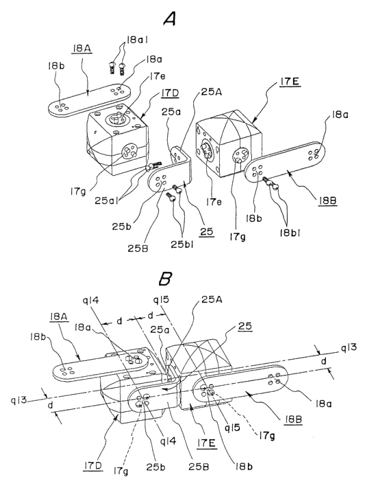
A best mode for carrying out the invention described in Claims 19 through 21
as a fifth
aspect of the present invention will be described with reference to Fig. 14.
Fig. 14 (A) also
shows the joint unit 17 shown as an example in Fig. 7 again, wherein fixed
joint receiving means
25b provided on one end of a L-shaped stay 25 is detachably connected by a
connecting screw
25b1 to the fixed joint means 17g provided on a joint unit 17D in the figure,
and the rotating joint
means 17e provided on anather joint unit 17E is detachably connected by a
connecting screw
25a1 to the rotating joint receiving means 25a provided on the other end of
the L-shaped stay
CA 02401208 2002-08-26
- 29 -
25. The L-shaped stay 25 itself is formed of a long L-shaped rigid member, and
is configured
such that one side portion 25B which extends to contain one end portion where
the fixed joint
receiving means 25b is provided and another side portion 25A which extends to
contain the
other end portion where the rotating joint receiving means 25a is provided
intersect orthogonally.
The fixed joint receiving means 25b of the one side portion 25B and the
rotating joint receiving
means 25a of the other side portion 25A may be of the same configuration,
e.g., both being
equivalent to the four fitting holes 18a1, 18a2, 18a3, and 18x4, serving as
the rotating joint
receiving means 18a on the connecting bar 18 shown as an example in Fig. 7.
Note that the
two connecting bars 18A and 18B in the figure are the same as those shown as
an example in
Fig. 7, wherein the rotating joint receiving means 18a of one connecting bar
18A is connectable
to the rotating joint means 17e of one joint unit 17D by a connecting screw
18a1, and the fixed
joint receiving means 18b of the other connecting bar 18B is connectable to
the freed joint
means 17g of the other joint unit 17E by a connecting screw 18b1. Fig. 14 (B)
is a perspective
view illustrating the state wherein the above-described parts are assembled,
and as indicated by
the additional lines in the figure, the separation distance between the center
axis q13 of the
rotating joint receiving means 25a of one side portion 25A of the L-shaped
stay 25 and the other
side portion 25B itself is set so as to be the joint means separation distance
d already described
with reference to Fig. 1. According to such a separation-distance setting, as
most clearly shown
in Fig. 14 (B),a pair of top faces, a pair of bottom faces and a pair of side
faces orthogonal to the
center axes q14 and q15 , of the two joint units 17D and 17E mutually
connected by means of
the L-shaped stay 25 are relatively rotationally driven following the
perimeter of a cylinder
having the center axis q13 shared by both joint units 17D and 17E as the
center axis thereof, so
that rotational driving on a shared center axis without unnatural sensations
is ensured. Applying
this in a more universal sense, the separation distance between the center
axis q14 of the fixed
joint receiving means 25b of one side portion 25B and the other side portion
25A itself may be
CA 02401208 2002-08-26
similarly set so as to be the joint means separation distance d, and the
separation distance
between the center axis q15 of the fixed joint means 17g of the joint unit 17E
connected to the
fixed joint receiving means 18b of the connecting bar 188, and the one side
portion 25A of the
L-shaped stay 25, may be similarly set so as to be the joint means separation
distance d.
A best mode for ranging out the invention described in Claims 22 through 24 as
a sixth
aspect of the present invention will be described with reference to Fig. 15
through Fig 16. A
dual-axis joint power transmission unit 26 is organized in a long plate-shaped
cubic casing 26a.
Encapsulated in the casing 26a is an input joint rotating shaft 26b rotatably
axially supported by
the casing 26 on a center axis q16 so as to pass through both top and bottom
faces of the
casing 26a to extend outward in the figure, an intermediate gear 26d
rotationally axially
supported by the casing 26 so as to mesh with a driving gear 26c rotating on
the input joint
rotating shaft 26b, and an output joint rotating shaft 26f rotatably axially
supported by the casing
28 on a center axis q17 so as to pass through both top and bottom faces of the
casing 26a to
extend outward in the figure and have a slave gear 26e rotating on the axis
q17 which slave
gear 26e fits perfectly into the intermediate gear 26d.
On the input joint rotating shaft 26b, fitting holes of the same
configurations as the four fitting
holes 18a1 through 18a4 serving as the rotating joint receiving means 18a
shown as an
example in Fig. 7, are detachably connected by the connecting screws 26b1 to
the rotating joint
means 17e on the joint unit 17B shown below in Fig. 15 (A}, wherein the
aforesaid fitting holes
pass through the shaft 26b longitudinally so that the top face of the casing
26a communicates
with the bottom face thereof. An input joint rotating shaft connecting means
is configured from
the fitting holes in the input joint rotating shaft 26b here and the
connecting screws 26b1. Also,
on the output joint rotating shaft 26f, fitting holes of the same
configuration as the four fitting
holes serving as the fixed joint receiving means 18b shown as an example in
Fig. 7,are
detachably connected by the connecting screws 26f1 to the fixed joint means
17g of the joint
CA 02401208 2002-08-26
unit 17C shown below in Fig. 15 (A),wherein the aforesaid fitting holes pass
through the shaft
2fif longitudinally so that the top face of the casing 26a communicates with
the bottom face
thereof. An output joint rotating shaft connecting means is configured from
the fitting holes in the
output joint rotating shaft 26f here and the connecting screws 26f1. Four
through holes 19a1,
19b1, 19c1, and 19d1 serving as the joint unit fixing receiving means bared
and displaced so as
to be aligned with the fixing screw hales 17a, 17b, 17c, and 17d, serving as
the joint unit fixing
means on the joint unit 17B shown below in Fig. 15 (A}, are provided around
the perimeter of
the driving gear 26c of the input joint rotating shaft 26b of the casing 26a,
and in the state that
the input joint rotating shaft 26b and the rotating joint means 17e are
connected, the joint unit
17B is fixed to the casing 26a by screwing the fixing screws 19a2, 19b2, 19c2,
and 19d2 to the
fixing screw holes 17a, 17b, 17c, and 17d, via the through holes 19a1, 19b1,
19c1, and 19d1.
Upon the rotating joint 17e of the faint unit 17B fixed to the casing 26 being
rotationally driven in
the counter-clockwise direction in the figure, the input joint rotating shaft
26b also rotates en
bloc in the counter-clockwise direction in the figure around the center axis
q16, the intermediate
gear 26d in tum rotates in the clockwise direction in the figure, and to
interact with this, further,
the output joint rotating shaft 26f rotates in the counter-clockwise direction
in the figure around
the center axis q17, and accordingly, the fixed joint means 17g of the joint
unit 17C rotates as
one body together with the output joint rotating shaft 26f. This results in
the joint unit C per se
rotating in the counter-clockwise direction in the figure around the center
axis q17, in the relative
relation with the dual-axis joint power transmission unit 26. With the
configuration illustrated as
an example in Fig. 15 (A}, the joint rotation converting means is configured
of the driving gear
2Ec rotating on the input joint rotating shaft 26b, and the intermediate gear
26d. While the slave
gear 26e rotating on the center axis q17 of the output joint rotating shaft
26f, and while the
rotations of the input joint rotating shaft 26b are converted into rotations
of the same speed and
in the same direction, provided that the gears are of the same diameter and
have the same
CA 02401208 2002-08-26
- 32 -
number of teeth to transmit the rotations to the output joint rotating shaft
26f, an arrangement
may be made by selecting the gear configuration wherein the rotations of a
changed speed as
well as in a reversed direction are transmitted to the output joint rotating
shaft 26f. Fig. 15 (B}
illustrates a perspective view of a structure wherein the casing 26a is closed
up by means of the
screws 26a1 with the components shown in the example in Fig. 15 (A~ being
encapsulated
therein. As can be clearly underst~d by reference to the additional lines in
the figure, the
separation distance in the longitudinal direction of the casing 26a between
the center axis q16
of the input joint rotating shaft 26b and the center axis q17 of the output
joint rotating shaft 26f
can be reduced to the minimum joint unit separation distance, and in this
case, both the joint
unit 17B connected to the input joint rotating shaft 26b and the joint unit
17G connected to the
output joint rotating shaft 26f have a uniform joint means separation distance
d, so that in the
case of the orthogonal dual-axis cylinder-like cube shown in the example in
Fig. ~, the minimum
joint unit separation distance Do2 here reaches a value equal to twice the
joint means
separation distance d. an the other hand, in another case, each of the joint
units connected to
the input joint rotating shaft 26b and the output joint rotating shaft 26f
have a unifom~ joint
means separation distance d, so that in the case of the uniaxial cylindrical
body shown in the
example in Fig. 2, the minimum joint unit separation distance Do1 here reaches
a value greater
than twice the joint means separation distance d.
Fig. 16 is a perspective view extracting and illustrating the two joint units
17B and 17G in
Fig. 13, wherein the rotating joint means 17e of the joint unit 17B is
connected to the input joint
rotating shaft 26b of the dual-axial joint power transmission unit 26, and the
fixed joint means
17g of the joint unit 17C is connected to the output joint rotating shaft 26f
of the dual-axial joint
power transmission unit 26. Upon the rotating joint means 17e of the joint
unit 17C being
rotationally driven in the clockwise direction in the figure around the center
axis q18 of the
rotating joint means 17e, the toe plate 24 connected to the rotating joint
means 17e is
CA 02401208 2002-08-26
-- 33 -
rotationally driven via the rotating joint receiving means 24a in the
clockwise direction in the
1"~gure around the Center axis q18, so that a rolling motion of the toe plate
24 wherein the toe tip
24b of the toe plate 24 rises, as shown in Fig. 76 (B), is secured. On the
other hand, upon the
rotating joint means 17e of the joint unit 17B being rotationally driven in
the clockwise direction
in the figure around the center axis q16 of the rotating joint means 17e, the
input joint rotating
shaft 26b of the dual-axial joint power transmission unit 26 is rotated in the
clockwise direction in
the figure around the center axis q16, the output joint rotating shaft 26f of
the unit 26 rotates in
the clockwise direction in the figure around the center axis q17, and as shown
in Fig. 16 (C), the
joint unit 17C connected to the rotating shaft 26f via the fixed joint means
17g rotates around
the center axis q17 in the clockwise direction in the figure, and
consequently, a pitching motion
of the toe plate 24 wherein the entire toe plate 2~ rotates in the clockwise
direction around the
center axis q17 is secured. The rotational motion using such a dual-axial
joint power
transmission unit 26 is characterized in that the center axis q18 for the
rolling motion of the toe
plate 24 and the center axis q17 for the pitching motion of the toe plate 24
orthogonally intersect
at an intersection q00, and due to such a characteristic, the movement of the
toe plate 24
appears to be a natural movement similar to the movement of the leg of a
living creature. ft can
be said that this characteristic is due to converting the rotations of the
rotating joint means 17e
of the joint unit 17B around the center axis q16 into rotations of the fined
joint means 1?'q of the
joint unit 17C around the center axis q17 by means of the dual-axial joint
power transmission
unit 26, in other words, in the figure, by shifting a rotating motion of the
center axis q16 at a
higher level which never intersects orthogonally with the center axis 18 to a
rotating motion of
the center axis q17 at a lower level which intersects orthogonally with the
center axis 18.
Conversely, as shown in Fig. 16 (D), assuming a case wherein between the
rotating joint
means 17e of the joint unit 17B and the fixed joint means 17g of the joint
unit 17c are connected
by a non-active member such as the connecting bar 18 shown in the example in
Fig. 7, as the
CA 02401208 2002-08-26
- 34 -
rotations of the rotating joint means 17e of the joint unit 17B progress, the
joint unit 17C is
rotationally driven around the center axis 16 of the rotating joint means 17e
of the joint unit 178
side, via the connecting bar 18. In this case, the rolling motions of the toe
plate 24 around the
center axis q18 are the same as those shown in the example in Fig. 16
(B),consequently the
pitching motion of the toe plate 24 being performed around the center axis q16
which never
intersects orthogonally with the center axis q18 of the rolling motion. This
causes an unnatural
rotational motion of the toe plate 24 to be encountered.
A best mode for carrying out the invention described in Claims 25 through 26
as a
seventh aspect of the present invention will be described with reference to
Fig. 17 through Fig
18. A zero-degree joint power transmission unit 27 is organized in a tong
plate-shaped cubic
casing 27a. Encapsulated in the casing 27a is an input joint fixed shaft 27b
fixed to fhe casing
27a on a center axis q19 so as to pass through both top and bottom faces of
the casing 27a in
the figure so as to extend outward, a first intermediate gear 27c rotationa!!y
axially supported by
the casing 27a so as to face an annular space 27g formed around the perimeter
of the input
joint f'~xed shaft 27b, a second intermediate gear 27d rotationally axially
supported by the casing
27a so as to mesh with the first intermediate gear 27c, and an output joint
rotating shaft 27f
rotatably axially supported by the casing 27a on a center axis q20 so as to
pass through both
top and bottom faces of the easing 27a to extend outward wherein a slave gear
27e having the
axis of aforesaid shaft 27f in common meshes with the second intermediate gear
27d. Now, a
rotation reversal converting means is configured of the firsfi intermediate
gear 27c, the second
intermediate gear 27d, and the slave gear 27e on the output joint rotating
shaft 27f, with the
rotations of an annular driving gear 28e being converted into reverse
rotations of a
predetermined speed, as described later. 4n the input joint fixed shaft 27d
are fitting holes of
the same configuration as the four fitting holes on the input joint rotating
shaft 26b shown in the
example in Fig. 15, detachably connected by the connecting screws 27b1 to the
rotating joint
CA 02401208 2002-08-26
- 35 -
means 17e an the joint unit 17B shown below in Fig. 17 (A),wherein the
aforesaid fitting holes
pass through the shaft 27b longitudlna!!y so that the top face of the casing
27a communicates
with the bottom face thereof. An input joint fixed shaft connecting means is
configured from the
fitting holes in the input joint fixed shaft 27d here and the connecting
screws 27b1. Also on the
output joint rotating shaft 27f, the fitting holes of the same configuration
as the four fitting holes
on the input joint rotating shaft 26b shown as an example in Fig. 18,are
detachably connected
by the connecting screws 27f1 to the fixed joint means 17g of the joint unit
17C shown below in
Fig. 17 {A), passing through the shaft 27f longitudinally with the top face of
the casing 27a
communicating with the bottom thereof. An output joint rotating shaft
connecting means is
configured from the fitting holes in the output joint rotating shaft 27f here
and the connecting
screws 27f1. Four connecting holes 28a, 28b, 28c, and 28d are bored and
displaced in four
corners of a connecting plate 28 formed of a square plate-shaped rigid member
serving as a
joint casing connecting means so as to be aligned with four fixing screw holes
19a, 19b, 19c,
and 19d, serving as a joint unit fining means on the joint unit 17B shown
below in Fig. 17 {A),
The connecting plate 28 can be attached to the upper face where the rotating
joint means 17e
of the joint unit 17B is provided in a conventional configuration. An annular
driving gear 28e is
formed at the center portion on the upper face of the connecting plate 28 in
the figure, having
annular outer teeth thereon, and a cylindrical space through which the upper
face of the annular
driving gear 28e of the connecting plate 28 communicates with the lower face
thereof in the
figure is formed on the inner center portion of the aforesaid annular driving
gear 28e. The
connecting plate 28 is assembled to the joint unit 17B in an attitude for the
connecting plate 28
to aNow the rotating joint means 17e to be encapsulated in a cylindrical space
formed in an
inner center portion of the annular driving outer gear 28e, so that the
rotating joint means 17e is
relatively rotational as to the annular gear 28e. Thus, the connecting plate
28 assembled to the
joint unit 17B is further assembled to the casing 27a in an attitude for the
connecting plate 28 to
CA 02401208 2002-08-26
- 36 -
allow the annular driving gear 28e to be movably inserted into an annular
space formed
surrounding the input joint fixed shaft 27b so as to ensure relative rotations
of the annular
driving gear 28e around the input joint fixed shaft 27b and also to ensure
meshing of the annular
outer teeth of the annular gear 27c with the first intermediate gear. Upon the
rotating joint
means 17e of the joint unit 17B fixed to the casing 27a being rotationally
driven in the counter-
clockwise direction in the figure, the rotating joint means 17e and the input
joint fixed shaft 27b
of the casing 27a also en bloc rotate in the counter-clockwise direction in
the figure around the
center axis q19 in the relative relation with the connecting plate 28, and
while such rotations are
in progress, the joint unit 17C on the center axis q20 of the casing 27a
perForms the orbits!
motion-like revolving motions in the counter-clockwise direction in the figure
around the center
axis q19. Meanwhile, the first intermediate gear 27c which meshes with the
annular outer teeth
of the annular gear 28e fixed to the joint unit 17B is caused to travel along
said annular outer
teeth to rotate in the counter-clockwise direction in the figure, whereby the
second intermediate
gear 27d rotates in turn in the clockwise direction in the figure, which
further causes the output
joint rotating shaft 27f to rotate in the counter-clockwise direction in the
figure on the center axis
q20, so that consequently, the joint unit 17C performs the rotations( motion
on it's center axis
q20 in the counter-clockwise direction in the figure, while performing the
aforesaid orbital
motion-like rotational motion in the counter-clockwise direction in the figure
on the center axis
q19. With the configuration illustrated as an example in Fig. 17 (A), joint
rotation converting
means are configured of the annular gear 18e on the center axis q19 of the
input joint fixed
shaft 27b, the first intermediate gear 27c, the second intermediate gear 27d,
and the slave gear
27e rotating around the center axis q20 of the output joint rotating shaft
27f, wherein, in the
example shown in the figure, the rotations of the rotating joint means 17e of
the joint unit 17B
are converted into rotations of the same speed and same direction, and
transmitted to the
output joint rotating shaft 27f, so for example, the 180° rotation of
the rotating joint means 17e
CA 02401208 2002-08-26
- 37 -
on the center axis q19 in the counter-clockwise direction in the figure are
accompanied by the
180° rotation of the output joint rotating shaft 27f on the center axis
q20 in the counter-clockwise
direction, so that consequently, taking the rotating joint means 17e as a
reference, the 360° {0°)
rotation in the counter-clockwise direction are ensured at the output faint
rotating shaft 27f. An
arrangement may be made by selecting the gear configuration wherein the speed
of the
rotations is changed to transmit the rotations of a different speed from that
of the rotating joint
means 17e to the output joint rotating shaft 27f.
Fig. 17 (B) illustrates a perspective view wherein the casing 27a is closed by
means of
screws 27a1 for the respective components shown in the example in Fig. 17 {A)
to be en bloc
assembled within the casing 27a. As can be clearly understood by rreference to
the additional
lines in the figure, only in the event that the separation distance in the
longitudinal direction of
the casing 27a between the center axis q19 of the input joint fixed shaft 27b
and the center axis
q20 of the output faint rotating shaft 27f can be reduced to the minimum joint
unit separation
distance Do2 ,the minimum joint unit separation distance Do2 here turns out to
be a value equal
to twice the joint means separation distance d. Fig. 18 is a perspective
explanatory diagram of
the configuration of a usage example wherein the configuration shown as an
example in Fig. 17
is assembled into a robot arm. As shown in Fig. 18 {A), the rotating joint
means 17e of the joint
unit 17B is connected to the input joint fixed shaft 27b of the zero-degree
joint power
transmission unit 27, and the fixed joint means 17g of the joint unit 17C is
connected to the
output joint rotating shaft 27f of the zero-degree joint power transmission
unit 27. Another joint
unit is connected to the fixed joint means 17g of the joint unit 17B via the
connecting bar 18, and
a third joint unit is further connected to the rotating joint means 17e of the
joint unit 17C via the
L-shaped stay 25. Upon the rotating joint means 17e of the joint unit 17B
rotating by 90° in the
clockwise direction in the figure, the entire zero-degree joint power
transmission unit 27 rotates
by 9Q° in the clockwise direction in the figure on the rotating joint
means 17e of the joint unit 178,
CA 02401208 2002-08-26
38 -
and causes the joint unit 17C to perform the orbital motion-like rotational
motion by that angle,
while the output joint rotating shaft 27f of the zero-degree joint power
transmission unit 27
rotates by 90° in the clockwise direction in the figure and causes the
joint unit 17G to perform
the rotating motion on it's center axis q20 by that angle on the rotating
shaft 27f as shown in Fig.
18 (B}, so that consequently, provided that the angular position of the
connecting bar 18
connected to the fixed joint means 17g of the joint unit 17B is defined as a
reference angular
position, the angular position of the L-shaped stay 25 connected to the
rotating joint means 17e
of the joint unit 17C can be rotated 180°, i.e., such an angular
position that the members 18
and 25 appear to stand in parallel with each other. In this case, the
90° rotations in the
clockwise direction in the figure of the joint unit 17C generated by the
90° incremental angular
position of rotations in the counter-clockwise direction in the figure of the
joint unit 17B per se is
also available. it is thus allowed for an rotatiana! angular position of
360° (0°} to be established
on the basis of the reference angular position of the connecting bar 18.
Conversely, as shown in Fig. 18 fiC), provided that the joint unit 17B and the
joint unit
17C are connected by a non-active member such as the connecting bar 18 for
example, instead
of the zero-degree joint power transmission unit 27, while the rotations in
the clockwise direction
in the figure of the rotating joint means 17e of the joint unit 17B are in
progress, the joint unit
~ 7G which remains fixed to the connecting bar 18 exclusively performs the
orbital motion-tike
rotational motion in the clockwise direction in the figure on the rotating
joint means 17e of the
joint unit 178. Accordingly, due to the mutual interference of the parts such
as shown in Fig. 18
{D), what is encountered here is such a disadvantage that the angular position
of the 360° (0°}
rotation of the L shaped stay 25 connected to the rotating joint means 17e of
the joint unit 17C
is subjected to decisive constraints, provided that the angular position of
the connecting bar 18
connected to the fixed joint means 17g of the joint unit 17B is defined as a
reference angular
position.
CA 02401208 2002-08-26
- 39
A best mode for carrying out the invention described in Claim 27 as an eighth
aspect of
the present invention will be described with reference to Fig. 19. The
structure shown as an
example in Fig. 19 is constructed by assembling unit sets for robots. The unit
sets for robots
shown here include the robot joint units 10, 11, 13, 14, 16, 17, shown in the
examples in Fig. 1,
Fig. 2, Fig. 4, and Fig. 7, the robof connecting bar 18 shown in the example
in Fig. 7, the single
stay 22 and double stay 23 shown in the example in Fig. 13, the robot t_-
shaped stay 25 shown
in the example in Fig. 14, the robot dual-axial joint power transmission unit
26 shown in the
example in Fig. 15, the robot zero-degree joint power transmission unit 27
shown in the
example in Fig. 17, and the robot toe plate 24 shown in the example in Fig. 13
and Fig. 16, and
a structure of various types of robots exhibiting a wide variety of functions
in wide variety of
forms can be enabled by appropriately assembling the various types of units
from the unit set
for robots here.
Industrial Applicability
According to the first aspect of the present invention, the surface profiles
of joint units are
formed as dice-tike cubes or uniaxial cylindrical bodies or orthogonal dual-
axis cylinder-like
cubes with uniform joint means separation distance, there lay providing joint
units advantageous
far reduction in size due to installation of the components stored in the
joint casing with high
density, and also with improved rotating motion functions due to increased
adjacency of the
rotating track of the joint casing.
According to the second aspect of the present invention, the joint means
comprise N
positioning projections disposed at equal intervals and equal angles around an
axis, and N
connecting screw holes disposed at positions rotated by 360°l2N
therefrom around the axis,
thereby providing a joint unit which is highly convenient in assembly
construction work in the
point that assembly of other members to the joint means at various angles is
easy.
According to the third aspect of the present invention, the rotating driving
means such as
CA 02401208 2002-08-26
a motor is made to be a plurality thereof cooperatively driving with one
intermediate gear
introduce therebefinreen, thereby providing a joint unit which is advantageous
in reduction of size
of the joint casing due to high-density mounting, from the point that the
multiple driving means
divided in small sizes can be dispersed and arrayed in high density in the
joint casing.
According to the fourth aspect of the present invention, a single stay
comprises on both
ends thereof N fitting holes capable of fitting to the N positioning
projections on the joint means
at each rotational position of 360°I2N around an axis, as joint
receiving means, and also, a
double stay comprises on both ends thereof axially supporting receiving means
such as axially
supporting holes or the like rotatabiy fitting to axially supporting means
such as axially
supporting pins disposed facing joint means on the casing surface of the joint
unit, thereby
providing single stays and double stays which are highly convenient far
assembly construction
work of joint units, from the point of facilitating connecting to the joint
units.
According to the fifth aspect of the present invention, an L-shaped stay
comprises joint
receiving means on both ends thereof, thereby providing an L-shaped stay which
is highly
convenient in the assembly construction work of joint units, from the point of
facilitating
connecting to joint units.
According to the sixth aspect of the present invention, a dual-axial joint
power
transmission unit converts and transmits the rotations of an input joint
rotating shaft connected
to the joint means of a joint unit fixed to the casing into rotations of an
output joint rotating shaft
disposed at a position distanced by a joint separation distance therefrom,
thereby providing a
dual-axial joint power transmission unit which improves rotation motion
functions of joint units
from the point that roAing motions and pitching motions of the joint unit on
two orthogonal axes
are enabled.
According to the seventh aspect of the present invention, a zero-degree joint
power
transmission unit converts and transmits the rotations of the joint unit
independently rotating
CA 02401208 2002-08-26
relatively as to an input joint fixed shaft fixed to the casing into rotations
of the output joint
rotating shaft disposed at a position distanced by a joint unit separation
distance therefrom,
thereby providing a zero-degree joint power transmission unit which improves
rotation motion
functions of joint units from the point that mutual 360° (0°)
rotation between the joint units is
enabled.
According to the eighth aspect of the present invention, a unit set for a
robot includes the
joint unit, the single stay, the double stay, the L-shaped stay, the dual-axis
joint power
transmission unit, and the zero-degree joint power transmission unit, thereby
providing a unit set
for robots capable of representing a wide variety of forms and a wide variety
of functions as a
robot structure. Such unit sets for robots have high industrial utility value.