Note: Descriptions are shown in the official language in which they were submitted.
CA 02401231 2002-08-26
WO 01/65827 PCT/JPO1/01497
PORTABLE INFORMATION TERMINAL AND
DIGITAL CAMERA FOR PORTABLE INJ~'ORMATION TERMCNAL
AND PORTABLE DIGITAL CAMERA INFORMATION TERMINAL SYSTEM
TECHNICAL FIELD
The present invention relates to a portable information terminal such as
portable
phones having earphone jack for sound input/output, PHS (personal handy-phone
system),
PDA (personal digital assistants), mobile personal computers, a digital camera
for use
with the portable information terminal, a portable digital camera/information
terminal
system comprised by a information terminal and a digital camera, and a method
of
controlling the portable information terminal.
BACKGROUND ART
In recent years, in the milieu of increasing speed of data communication using
portable information terminals and significant progress that has been achieved
in
information communication technologies, portable telephones have transformed
themselves from a usage as telephone to an integrated information tool that is
being
accepted rapidly.
With such a trend, customer needs have expanded from basic information such as
images, music, mail to higher levels of content such as moving images and
programs, and
it is anticipated that even more applications will be created in the future.
In response to such needs of consumers, machines that might be termed
information vending machines have begun to appear in the marketplace to
provide a
service of selling not only sound data information but information of various
other kinds
that can be accessed by connecting a portable information terminal to the
information
vending machine with a special cable.
When receiving information from an information vending machine using such a
special cable, it is necessary to insert a connector of the cable to the
portable terminal, but
one problem of inconvenience has been that, because the connector has a front
side and a
back side to ensure that the connection is made in a fixed direction,
resulting in a problem
of inconvenience that the user must confirm front and back surfaces of the
connector.
Also, when the connector is inserted into the portable terminal, locking
mechanism of the connector operates and the connection becomes locked, but if
the user
CA 02401231 2002-08-26
WO 01/65827 PCT/JPO1/01497
2
tries to pull the connector out without realizing that it is locked, the
connector can be
subjected to excessive load and damage may result. Also, when the portable
telephone and
PHS are used as a communication device for mobile computing, PC card is
normally used
as an interface, and therefore, it is necessary to carry PC card and
connection cables when
one is travelling, which present another inconvenience. Also, some computers
have only
one PCMIA (personal computer memory card international association) slot for
inserting a
PC (personal computer) card so that, when this slot is taken up by the
portable telephone,
other devices cannot be connected, which has been an annoyance. Further, if it
is desired
to use some peripheral device, the PC card inserted into the PCMIA slot must
be
exchanged to another card, resulting in a problem of time-consuming handling.
In the meantime, in response to a need for transmitting images recorded in a
digital camera to another terminal by connecting the digital camera to the
portable
terminal, Japanese Patent Applications, First Publications, Hei 10-341302 and
Hei 11-
08823 disclose a technique of chord-based connections such as IRDA (infrared
data
access) or RS-232C to connect the digital camera to the portable terminal for
transmitting
the data.
However, for transferring image data using chords such as IRDA or RS232C,
problems are handling and portability.
Also, conventional digital cameras are expected to be connectable to various
general portable communication terminals such as portable telephone terminal,
PHS, PDA,
mobile personal computers, so that, even though a display section such as
liquid crystal
monitor and an operation section are provided for the portable terminal, they
are often
provided for the digital camera also, and handling becomes complex and the
cost of the
combined system increases. Also, because it is not possible to supply power
from a device
to which the camera is connected, the camera itself must have a power source,
and the size
of the casing increases, thus present a problem that it is unsuitable as a
portable device. As
explained above, it has been.difficult, in the past, to avoid the complexity
of camera
structure and realize a highly convenient digital camera.
Also, image data are generally transferred serially according to EIA
(Electronic
Industry Association) standard, but IRDA and RS-232 and others always require
special
interfaces. Also, in addition to data transfer methods using cables as
described above, a
Japanese Patent Application, First Publication, Hei 06-268582 discloses a
technique of
data transfer through a medium such as a memory card, but even when using such
a
CA 02401231 2002-08-26
WO 01/65827 PCT/JPO1/01497
3
technique, interface circuit and driver circuit are necessary. For this
reason, when
connecting a digital camera to a portable communication terminal, expensive
parts and
interfaces are required in the past, present a problem that it has been
difficult to reduce the
size of the digital cameras and portable terminals or to reduce the combined
system cost.
Furthermore, when using RS-232C cable such as the one described above, serial
communication according to EIA RS-2320 standard is used, but in normal serial
communication, it is necessary to perform an operation, the so-called
"handshake
operation", by exchanging certain commands between the portable terminal and
the digital
camera, before commencing communication so that image data are transferred
after
confirming that both sides are in operational states, resulting a problem that
image data
transfer operation cannot be started promptly. Also, in serial communication,
information
to discriminate start and finish of individual data is attached to each byte
(=8 bits} of data,
so that, when 2-bits of the 8-bits are used for discrimination purpose, the
amount of
information that can be carried by 1 byte is only 6 bits, leading to a problem
that the data
themselves are not being processed efficiently. In addition to this problem,
although
parallel communication that increases the transfer speed by increasing the
number of serial
lines is known, the parallel data transfer technique is not preferable because
it increases
the system cost due to the fact that the number of signal lines must be
increased in the
connection terminal of the devices such as digital camera and portable
communication
terminal that demand small size, light weight and low cost.
Also, when recording images with a digital camera, the user must perform
several
operations, such as: selecting the image recording mode by operating the keys
of the
operation section provided on the portable terminal while confirming the
settings on the
display section of the terminal; pressing the define key to define the image
recording
mode; and then recording an image in the image recording mode. Furthermore,
when the
portable terminal is a portable telephone, for example, it is necessary to
operate at least
two keys, one key for switching from the sound mode of the telephone function
to the
image recording mode of the camera function, and another key to define a task
in the
selected mode. Further, it is necessary to provide operation keys required for
image
recording, for example, a key to function as the shutter button, and settings
keys to specify
recording conditions and others. Therefore, the number of keys to be operated
such as
switching to the recording mode and operating the camera are increased,
resulting in a
problem that, when one is ready to record a picture, some time is spent in
operating the
CA 02401231 2002-08-26
WO 01/65827 PCT/JPO1/01497
4
keys before reaching the stage of defining the recording mode. And, to define
the image
recording mode, it is necessary to select the image recording mode first and
then to
operate the definition keys, so that the user is required to view the display
section of the
portable terminal while operating the keys to define parameters of the image
recording
mode, so that the problems are not only complex key operations but missed an
opportunity
for recording good images.
The present invention is provided in view of the background information
present
above, and an object one is to provide a portable information terminal that
enables to
communicate data with an external device in a highly convenient manner because
of its
simplified cable connection.
An object two is to provide a user-friendly digital camera that enables to
freely
change the direction of image recording without making the camera structure
complex for
use with a portable information terminal having an earphone jack for sound
input/output,
and a portable information terminal for use with such a digital camera, and a
digital
camera/information terminal combination system.
And, by virtue of the fact that a portable information terminal is already
provided
with an earphone jack for sound input/output purposes so that this jack can be
used for
transferring data purposes, so that an object three is to provide a portable
information
terminal and a digital camera for the information terminal and a portable
digital
cameralinformation terminal system that does not require a special connection
device or
expensive interfaces.
An object four is to provide a portable information terminal, and a digital
camera
for the portable information terminal and a portable digital
camera/information terminal
system that enables to transmit image data easily, rapidly and ei~iciently
using serial
transmission in particular.
An object five is to provide a portable information terminal and a method for
controlling the portable information terminal that can be operated using a
lesser number of
keys without the need to look at the screen in the display section and without
providing a
dedicated key for image recording.
DISCLOSURE OF INVENTION
According to aspect one of the present invention, a portable information
terminal
comprising a jack having a first and a second transfer contacts for
transmitting-receiving
CA 02401231 2002-08-26
WO 01/65827 PCT/JPO1/01497
data, which connects to a contact for transmitting/receiving data 173, 174 of
the connector
101 shown in Figure 12. According to this structure, because there are two
contacts for
data communication, it enables to connect to a connector such as a USB
connector having
a similar structure.
Aspect two of the portable information terminal relates to the jack further
comprises a power supply contact, which connects to a contact for the power
supply 171
of the connector 101 shown in Figure 12, and a ground contact, which connects
to a
contact for the ground 172 of the connector 101 shown in Figure 12. According
to this
structure, because the power supply contact and the ground contact are
provided, power
can be supplied from an external source.
Aspect three of the portable information terminal relates to the jack having
contacts arranged in order, from an inner side toward an outer side of the
terminal body,
the first data transfer contact, the second data transfer contact, the ground
contact, and the
power supply contact. According to this structure, because a case section
having a large
contact area is selected as the contact for the power supply, problem of poor
contact can be
avoided even when it is rotated in complement. Also, incomplete insertion of
the plug
does not cause power shorting because nearby contact is transmitted. In
particular, the
terminal side troubles are prevented because the power supply contact and the
ground
contact are arranged in the same way as an earphone plug.
Aspect four of the portable information terminal relates to the jack is usable
with
an earphone jack. According to this structure, because an earphone jack in any
existing
portable information terminal can be used as data communication terminal,
there is no
need for providing a new connector for USB cable connection. Also, the
earphone jack
can be rotated 360 degrees about the plug axis, and because there is no need
to confirm the
orientation of the USB connector for insertion into the jack, it is convenient
to use. Further,
because there is no locking device for the earphone jack, the plug connector
may be
removed without concern to potential damage. Portable telephone, PHS, PDA are
examples of portable information terminals that can use the jack as earphone
jack.
Aspect seven of the portable information terminal relates to the jack the
first data
transfer contact, corresponding to the contact for transferring data 11d of
the plug 10 of
the digital camera l, is usable for data line and the second data transfer
contact,
corresponding to the contact for transferring a clock signal 11 c of the plug
10 of the digital
camera 1, is usable for a clock signal line.
CA 02401231 2002-08-26
WO 01/65827 PCT/JPO1/01497
6
According to this structure, contacts for earphone microphone can be used to
transfer image data produced by the digital camera, and it contributes to
making a multi-
purpose portable information terminal.
Aspect eleven of the portable information terminal, further comprising a
circuit
switching section (switching section 125 or 126 in the embodiment) which
connects the
jack to a sound circuit (sound interface 19a in the embodiment) or a data
processing circuit
(ITSB interface 19c in the embodiment).
According to this structure, a circuit (interface) for processing input data
can be
switched to suit an external device connected to the jack, data processing
appropriate to
the external device can be carried out.
Aspect sixteen of the portable information terminal relates to the circuit
switching
section connects the jack to the data processing circuit (LJSB interface 19c)
when
information relating to data transfer start is input to the circuit switching
section (in the
embodiment described later, when the user uses the operation section 23 to
switch to the
1 S USB mode, and a signal so notifying is input from CPU 26, or a specific
signal to indicate
that USB cable 100 has been connected is input by an external device).
According to this structure, when it is detected that USB cable has been
connected, the circuit switching section automatically switches the target
connection of the
earphone jack, so that processing to suit various data output from the
earphone jack can be
performed.
Aspect seventeen of the invention relates to an information terminal
comprising a
jack having four contacts for a power supply, a ground, transferring a clock
signal and
transferring data.
According to this portable information terminal, it enables to directly attach
the
camera mechanically as well as electrically to the portable information
terminal by
inserting a plug of the digital camera into the jack.
Aspect eighteen of the portable information terminal relates to the four
contacts
of the jack are arranged in order, from an inner side toward an outer side of
the terminal
body, the contact for transferring data, the contact for transferring the
clock signal, the
contact for the ground, and the contact for the power supply.
Accordingly, by selecting the case section that has a large contact area as
the
contact for the power supply, the problem of improper contact can be avoided
even when
it is rotated in complement. Also, when the plug is only partially inserted,
shorting can be
CA 02401231 2002-08-26
WO 01/65827 PCT/JPO1/01497
7
avoided because there are no nearby terminals. In the case of earphone
microphone, the
contact for the ground is second from the base section so that problems in the
terminal can
be prevented.
Aspect nineteen ofthe portable information terminal relates to the jack is
usable
with an earphone j ack.
According to this structure, because an earphone jack on an existing portable
information terminal can be used to perform image data transfer, there is no
need to
provide a new jack for connecting the digital camera. Also, the portable
information
terminal that can use the jack as the earphone jack includes portable
telephone, PHS, and
PDA, for example.
Aspect twenty one of the portable information terminal relates to the circuit
switching section (switching section 25) which selects either a sound circuit
(sound
interface 19a) or an imaging circuit (imaging interface 19b) according to a
signal input
into the jack and then connects the selected circuit to the jack.
According to this structure, image recording can be started simply by
connecting
the digital camera.
Aspect twenty four of the portable information terminal relates to the circuit
switching section identifying a connected external device, when a plug of an
external
device connected to the jack, by measuring an electrical resistance between
predetermined
contacts of the plug, so that it enables to identify a device connected
thereto using a simple
circuitry.
Aspect twenty five relates to a digital camera for a portable information
terminal
to which the portable information terminal, having a jack for inputloutput of
signals
including sound signals, can be connected, comprising a digital camera body
having a
plug for detachably connecting to the jack, wherein the plug has a circular
transverse
cross-sectional shape.
According to this structure of the digital camera fox the portable information
terminal, a digital camera body having a plug for detechably connecting to the
jack, so that,
when the plug is inserted into the jack of the portable information terminal,
the recording
angle can be chosen at any direction within the 360 degrees and can be
adjusted to any
direction by rotating the plug about the axis.
Furthermore the plug of the digital camera is connected by inserting directly
into
the jack of the portable information terminal, the two devices axe made into
one terminal
CA 02401231 2002-08-26
WO 01/65827 PCT/JPO1/01497
8
by being mechanically and electrically connected to each other. Therefore, a
connecting
cable that was required in the past is no longer required, and because the
digital camera
and the portable information terminal are converted into a single terminal, it
enables one-
hand image recording operation.
Aspect twenty six relates to the digital camera for the portable information
terminal, in which the plug is disposed so that a tip end of the plug is
substantially
perpendicular to an optical axis of a lens of the digital camera.
Accordingly, when the plug is connected to the jack which is normally provided
on a lateral surface of the portable information terminal, the digital camera
can be
operated while observing the display section of the portable information
terminal.
Aspect twenty seven relates to a switching section provided in either the
digital
camera body or the information terminal for switching between a sound circuit
and an
imaging circuit, and when the jack and the plug are connected electrically,
image data are
transferred from the digital camera side to the information terminal by way of
the plug and
the j ack.
Accordingly, image recording operation can be started by simply connecting the
digital camera.
Aspect twenty nine relates to a mound section provided around a periphery of
the
plug of the digital camera body, so that, when the plug is inserted into the
jack, the mound
section is abutted against a periphery of the jack so that when the digital
camera is rotated,
a surface of the mound section is made to slide against the periphery of the
jack.
According to this structure, the digital camera can be readily rotated against
the portable
information terminal, and in this case, the mound section is preferably formed
in a
convex-shape.
Aspect thirty two relates to the plug of the digital camera provided with four
contacts for a power supply, a ground, transferring a clock signal, and
transferring data.
Accordingly, the digital camera can be operated using the power supplied from
the portable information terminal and transmit the recorded image data to the
portable
information terminal.
Aspect thirty six relates to the four contacts arranged in order, starting
from a
base section of the digital camera body side, the contact for power supply,
the contact for
the ground, the contact for transferring the clock signal, and the contact for
transferring
the data.
CA 02401231 2002-08-26
WO 01/65827 PCT/JPO1/01497
9
Accordingly, by selecting the case section that has a large contact area as
the
contact for power supply, the problem of improper contact can be avoided even
when it is
rotated in complement. Also, when the plug is only partially inserted,
shorting can be
avoided because there are no nearby terminals. In the case of earphone
microphone, the
ground section is second from the base section so that troubles in the
terminal can be
prevented.
Aspect thirty seven relates to the contact for ground and the contact for
transferring the clock signal of the plug are electrically isolated.
According to this structure, by detecting the resistance value between the
contacts,
it enables to inform a portable information terminal that a digital camera is
connected to
the portable information terminal.
Aspect thirty nine relates to the digital camera having an insertion section
for
threading a cable, so that a string shaped object can be used to thread
through the insertion
section to facilitate carrying the camera.
Aspect forty relates to the digital camera for the portable information
terminal
having: a movable member which supports the plug so as to be movable with the
plug;
and a guide section which supports the movable member so as to be freely
movable along
a longitudinal axis of the plug and to enable the plug to be housed in the
digital camera
body, so that the plug can be stored in the body itself.
Aspect forty one relates to a lens cover of the digital camera for protecting
the
lens of the digital camera, and the lens cover is detachable from the lens by
moving it with
the movable member, so that the lens can be protected from dust and impact.
In a digital camera having such a structure, by connecting the plug and the
portable information terminal using a cable having a first terminal for
connecting to the
plug electrically and a second terminal for transmitting information output
from the plug,
it enables the camera to be moved laterally as well as vertically.
Accordingly, it enables to
record images over an even wider range.
Aspects forty two relates to a portable digital cameralinformation terminal
system
comprising a portable information terminal according to claim 18, and a
digital camera for
a portable information terminal according to claim 36 connected to the
portable
information terminal.
Aspects forty three relates to a portable digital cameralinformation terminal
system comprising a portable information terminal according to claim 24, and a
digital
CA 02401231 2002-08-26
WO 01/65827 PCT/JPO1/01497
camera for a portable information terminal according to claim 37 connected to
the portable
information terminal.
According to this structure, by detecting the resistance value between the
contacts,
it enables to inform a portable information terminal that a digital camera is
connected to
the portable information terminal.
Aspect forty four relates to a portable information terminal having a contact
for
receiving data and a contact for transferring a clock signal.
According to this structure, image data can be input from the digital camera
into
the portable information terminal in a simple manner. Also, any earphone jack
that is
10 provided in a conventional portable telephone can be used for the contact
for receiving
data and the contact for transferring the clock signal, so that there is no
need for providing
a new terminal.
Aspect forty five relates to the portable information terminal further
comprising a
contact for transmitting data. This is so that, by providing a contact for
transmitting data
and connecting the contact for receiving data of the digital camera, the
portable
information terminal is able to operate the digital camera. By so doing, bi-
direction data
transfer is made possible. Also, because the earphone jack of conventional
portable
information terminal has four channels, such an earphone jack can be adopted
for the
present use even if the contact for receiving data is further provided to
result in three
contacts.
Aspect forty six relates to the portable information terminal having a first
digital
camera connection recognizing section, which comprises a control section, for
recognizing
that a digital camera has been connected to the portable information terminal,
when a
clock signal is input in the contact for transferring the clock signal.
According to this structure, simply by having the clock signal input when an
external device is connected, the external device can be determined to be the
digital
camera.
Aspect forty eight relates to the clock line section provided with a second
digital
camera connection recognizing section, which comprises a control section, for
starting a
generation of a clock signal when an external device is connected, and for
recognizing that
the external device is a digital camera when predetermined data are received
by the
contact for data receiving.
According to this structure, by supplying clock signals and discriminating the
CA 02401231 2002-08-26
WO 01/65827 PCT/JPO1/01497
11
data input from an external device corresponding to the clock signal, an
external device
can be discriminated.
Aspect fifty relates to a digital camera for a portable information terminal
having
two contacts comprising a contact for transmitting data and a contact for
transferring a
clock signal.
According to this structure, so long as the device connected has a contact
with
two contacts, image data can be transmitted to the connected device in a
simple manner
without using a complex interface and the like.
Aspect fifty one relates to the digital camera for a portable information
terminal
having a contact for receiving data.
According to this structure, data reception becomes possible, and for example,
it
enables to operate the digital camera from a device being connected to the
digital camera.
Aspect fifty two relates to the digital camera for a portable information
terminal
further having a control section which outputs through the contact for
transferring the
clock signal a clock signal to the external device when the external device is
connected.
According to this structure, by outputting a clock signal from the contact for
transferring the clock signal, it enables the device to which the camera is
connected to
recognize that the digital camera has been connected.
Aspect fifty four relates to the digital camera for a portable information
terminal
such that when the control section receives the clock signal by way of the
contact for
transferring the clock signal, the control section outputs predetermined data
through the
contact for transmitting data.
According to this structure, by transmitting the predetermined data in
response to
clock signal output from the connected device, it enables the device to which
the camera is
connected to readily recognize that the digital camera has been connected.
Aspect fifty six relates to a portable digital camera/information terminal
system
comprising a portable information terminal according to aspect of forty four,
and a digital
camera according to aspect fifty connected to the portable information
terminal.
As described above, the present portable information terminal is provided with
a
contact for transferring a clock signal and a contact for receiving data, and
also, the digital
camera is provided with a contact for transferring a clock signal and a
contact for
transmitting data so that by connecting mutually corresponding contacts, the
portable
information terminal is able to carry out the task of discriminating the
external device, or
CA 02401231 2002-08-26
WO 01/65827 PCT/JPO1/01497
12
recognizing that the digital camera is being connected, and also, by
transmitting image
data to the portable information terminal, any images can be displayed on the
display
section of the portable information terminal. In a case where there is only
one data line
each, it is not possible to operate the digital camera from the portable
information terminal,
so that it is preferable to provide a memory of suffcient capacity to store
image data that
would be transmitted from the digital camera. Also, in addition to the two
contacts, by
providing a contact for transmitting data for the portable information
terminal and a
contact for receiving data for the digital camera, it becomes possible to
operate the digital
camera from the portable information terminal. In this case, when the portable
information
terminal recognizes that the digital camera has been connected as an external
device,
internal circuits of the portable information terminal are switched to
functions to serve the
digital camera so that the digital camera can be operated from the portable
information
terminal by having the operation section becoming the digital camera operation
section,
for example. The contacts in each are at most three, so that the earphone j
ack of the
existing portable information terminal may be adopted as it is for use, and
there is no need
for providing a special terminal. For communication between two devices,
regardless of
whether it is uni- or bi-directional, the pacing synchronized method represent
typically by
clock synchronized serial interface and UART (universal asynchronous
receiver/transmitter) may be used.
Aspect sixty two relates to a portable information terminal comprising: a
terminal
side detection section which detects a transmit-ready signal to indicate a
data transmit-able
state transmitted from a digital camera; and a receiving section which
receives image data
transmitted from the digital camera; wherein the receiving section receives
image data
after the terminal side detection section has detected a transmit-ready
signal.
Aspect sixty three relates to the portable information terminal wherein, when
the
receiving section receives image data, the receiving section detects an
abnormality
according to a reception abnormality discrimination signal contained in the
received image
data.
Aspect sixty four relates to the portable information terminal, further
comprising
an terminal side outputting section which outputs a transmit-request signal to
request
image data to be transmitted, wherein, when the terminal side detection
section detects the
transmit-ready signal, the terminal side outputting section outputs the
transmit-request
signal to the digital camera, and the receiving section receives image data
transmit from
CA 02401231 2002-08-26
WO 01/65827 PCT/JPO1/01497
13
the digital camera in response to the transmit-request signal.
Aspect sixty six relates to the portable information terminal, wherein the
receiving section receives image data in one block when the transmit-request
signal is not
interrupted.
Aspect sixty seven relates to a digital camera for a portable information
terminal
for a portable information terminal, comprising: a camera side outputting
section which
outputs a transmit-ready signal to indicate an image data transmit-able state
to the portable
information terminal; and a transmitting section which transmits image data in
one block
to the portable information terminal; wherein the transmitting section
transmits image data
to the portable information terminal after the camera side outputting section
outputs a
transmit-ready signal.
Aspect sixty eight relates to the digital camera for a portable information
terminal
having camera side outputting section for detecting a transmit-request
notification output
from the portable information terminal requesting image data to be
transmitted, and when
the camera side detection section detect the transmit-request signal after the
camera side
detection section output a transmit-ready signal, the transmitting section
transmit image
data to the portable information terminal.
Aspect sixty nine relates to a portable digital cameraJinformation terminal
system
comprising a portable information terminal according to one of claim 62 and a
digital
camera for a portable information terminal according to claim 67 connected to
the
information terminal.
Aspect seventy seven relates to a method for controlling a portable
information
terminal to which a digital camera can be connected, wherein when the digital
camera is
connected to the portable information terminal body and a predetermined key
provided in
an operation section of the portable information terminal is pressed for a
predetermined
period of time, the digital camera is placed in a recording state, and in such
a condition, if
a key or plurality of keys in the operation section is operated, an operation
corresponding
to a recording function assigned to the key is executed.
Accordingly, there is no need to provide a dedicated key for image recording
purpose, so that the lesser number of keys are needed for operation for image
recording,
and it eliminates the need to switch to the recording mode and to operate in
the recording
mode while confirming each item on the display section.
Aspect seventy eight relates to the method for controlling a portable
information
CA 02401231 2002-08-26
WO 01/65827 PCT/JPO1/01497
14
terminal, wherein, the digital camera is placed and maintained in the
recording state, and
when a key of the plurality of keys in the operation section is pressed for a
period of time
shorter than the predetermined period of time, an operation assigned to the
pressed key
corresponding to a recording function of the digital camera under the
recording state is
executed, and in such a condition, if a key of the keys in the operation
section is pressed
for the predetermined period time, the portable information terminal is placed
in a certain
key input enabled state.
Here, a certain state demanded by an input-key relates to a state enabled by
an
input-key such as a start call operation, parameter settings for telephone
function or data
communication function, composing mails and telephone number entries.
Accordingly,
switching between an operational state for communication {com mode) and an
operational
state for image recording (recording mode) is facilitated so that the user-
friendly system is
provided.
Aspect seventy nine relates to a method for controlling a portable information
terminal to which a digital camera can be connected, wherein when the digital
camera is
connected to the portable information terminal body and a predetermined key
provided in
an operation section of the portable information terminal is pressed for a
predetermined
period of time, the digital camera is placed in a recording state, and in such
a condition, if
a predetermined key in the operation section is operated, an operation
corresponding to a
recording function assigned to the predetermined key is executed.
According to this method, by operating one key, the operating mode can be
switched from the com mode to recording mode, so that key pressing error is
eliminated
and the process is made effortless.
Aspect eighty relates to A portable information terminal to which a digital
camera
can be connected, comprising: operation section having a plurality of keys;
and control
cP~tinn fnr nnntrnllin~ the nnrtahle infnrmatinn terminal in Inch a manner
that_ when the
CA 02401231 2002-08-26
WO 01/65827 PCT/JPO1/01497
mode and to operate in the recording mode while confirming each item on the
display
section.
Aspect eighty one relates to the portable information terminal, wherein the
control section controls the portable information terminal in such a manner
that, the digital
camera is placed and maintained in the recording state, and when a key of the
plurality of
keys in the operation section is pressed for a period of time shorter than the
predetermined
period of time, an operation assigned to the pressed key corresponding to a
recording
function of the digital camera under the recording state is executed, and in
such a
condition, if a key of the keys in the operation section is pressed for the
predetermined
10 period time, the portable information terminal is placed in a certain key
input enabled
state.
Accordingly, switching between an operational state for communication (com
mode) and an operational state for image recording (recording mode) is
facilitated so that
the user-friendly system is provided.
15 Aspect eighty two relates to a portable information terminal to which a
digital
camera can be connected, comprising: operation section having a plurality of
keys; and
control section for controlling the portable information terminal in such a
manner that,
when the camera is connected to a portable information terminal body and a
predetermined key provided in an operation section of the portable information
terminal is
pressed for a predetermined period of time, the digital camera is placed in a
recording
state, and in such a condition, if a predetermined key in the operation
section is operated,
an operation corresponding to a recording function assigned to the
predetermined key is
executed.
Accordingly, by operating one key, the operating mode can be switched from the
com mode to recording mode, so that key pressing error is eliminated and the
process is
made effortless.
BRIEF DESCRIPTION OF DRAWINGS
Figures 1A is a front view of a digital camera for a portable information
terminal
in Embodiment 1-1.
Figures 1B is a side view of a digital camera for a portable information
terminal
in Embodiment 1-1.
Figures 1C is a bottom view of a digital camera for a portable information
CA 02401231 2002-08-26
WO 01/65827 PCT/JPO1/01497
16
terminal in Embodiment 1-1.
Figures 1D is a perspective view of a digital camera for a portable
information
terminal in Embodiment 1-1.
Figure 2 is an exploded perspective view of the digital camera for the
portable
information terminal in Embodiment 1-1.
Figure 3 is a diagram to explain the connecting state of the digital camera
for the
portable information terminal.
Figure 4 is a block diagram of a circuit in the connection state of the
digital
camera for the portable information terminal.
Figure 5A is a flowchart for the process of image recording and transmitting
the
recorded image information.
Figure 5B is a flowchart for the process of image recording and transmitting
the
recorded image information.
Figure 6A is a diagram to explain a method of using the digital camera.
Figure 6B is a diagram to explain a method of using the digital camera.
Figure 7 is an example of plugging an earphone microphone.
Figure 8 is an example of plugging a stereo headphone.
Figure 9 is a schematic diagram of connecting an information terminal and a
digital camera using a dedicated extension cable.
Figure 10 is an example of using the dedicated extension cable as a strap for
connecting the digital camera and the portable information terminal.
Figure 11 shows an external appearance of the digital camera having a housing
for storing the plug and a guide.
Figure 12 is an illustration of a USB cable 100 used in Embodiment 1-2.
Figure 13 is a block diagram of a circuit configuration of a portable
information
terminal in Embodiment 1-2.
Figure 14 is a block diagram of a circuit configuration of a portable
information
terminal in Embodiment 1-3.
Figure 15 is an illustration of a portable digital camera connection apparatus
comprised by a portable information terminal and a digital camera.
Figure 16 is a block diagram of the circuit configuration of the portable
digital
camera connection apparatus.
CA 02401231 2002-08-26
WO 01/65827 PCT/JPO1/01497
17
Figure 17 shows examples of timing charts of, respectively, output waveforms
of
(a) the clock line and (b) the data line of the of the digital camera, from
each output
terminal of the portable information terminal and the digital camera at two
contacts.
Figure 18 shows examples of timing charts of, respectively, output waveforms
of
(a) the clock line and (b) the data line of the of the digital camera, from
each output
terminal of the portable information terminal and the digital camera at two
contacts.
Figure 19 shows examples of timing charts of, respectively, output waveforms
of
(a) clock line and (b) data line of the of the digital camera, and of (c) data
line of the
portable information terminal from each output terminal of the portable
information
terminal and the digital camera at three contacts.
Figure 20 shows examples of timing charts of, respectively, output waveforms
of
(a) clock line and (b) data line of the of the digital camera, and of (c) data
line of the
portable information terminal from each output terminal of the portable
information
terminal and the digital camera at three contacts.
Figure 21 shows a timing chart of the output waveform from the data line of
the
digital camera in Figures 18, 20.
Figure 22 is a block diagram of the configuration a portable telephone
terminal
and a digital camera in Embodiment 3.
Figure 23 shows timing charts timing chart for transmitting image data from
the
digital camera 650 to the portable telephone terminal 630.
Figure 24 is a diagram of the structure of image data S 1.
Figure 25 shows timing charts for clock signal output to data request signal
line
L 1 b and image data output to data output signal line L 1 c.
Figure 26 is a diagram of an example of a table showing items contained in a
header 400a.
Figure 27 is a diagram of an example of the values of an end marker 400c
comprised by data of 2 bytes.
Figure 28 is a diagram of an example of the output sequence of image data body
400b in image data S 1.
Figure 29 is a block diagram of the configuration of a portable information
terminal in Embodiment 4.
Figure 30 is a diagram of the keyboard in the operation section of the
portable
information terminal in Embodiment 4 shown in Figure 29.
CA 02401231 2002-08-26
WO 01/65827 PCT/JPO1/01497
18
Figure 31 is a flowchart of the control process of the portable information
terminal in Embodiment 4 shown in Figure 29.
Figure 32 is a flowchart of the control process of the portable information
terminal in Embodiment 4 shown in Figure 29.
BEST MODE FOR CARRYING OUT THE INVENTION
Preferred embodiments of the present invention will be explained in detail in
the
following.
Figure 1 shows a digital camera for use with a portable information terminal
(referred simply as the digital camera in the following), lA~lD are,
respectively, a front
view, a side view, a bottom view and a perspective view of the digital camera
for the
portable information terminal in Embodiment 1-1
Figure 2 shows an exploded perspective view of the digital camera in this
embodiment. The digital camera is comprised by: a top cover 2; infra-red
absorbing filter
3; a lens-barrel 4 construct the lens system of the camera; a holder 5 for
positioning the
lens-barrel 4 and blocking light from outside of the optical axis to the
imaging element; a
reflection prevention film 6 for eliminating harmful reflection light; a CMOS-
IC7 for
processing imaging element and image data; a base plate 8 for mounting IC7 and
other
electronic parts; and a bottom cover 9.
On the lower surface of the top cover 2 and the bottom cover 9, semi-circular
cutout sections 2a, 9a are provided. Behind each of the cutout sections 2a and
9a, support
plates 2b, 9b are provided, and each cutout further has respective support
plates 2b, 9b
having a cutout each. Here, CMOS-IC7 may be replaced with a CCD-IC.
The plug 10 is attached to the camera body by inserting the bottom section of
the
base section 10a of the plug 10 between the cutouts 9a 9b of the lower cover 9
and
assembling the parts 2~8, placing the top cover 2 and inserting the top
section of the base
section 10a between the cutout 2a and the support plate 2b. Arranged in
sequence in the
plug 10 are, from the base section 10a side, a contact for power supply 11a, a
contact for a
ground l 1b, a contact for transferring a clock signal l lc, a contact for
transferring data
11d. The top cover 2 and the lower cover 9 are fixed by screws (not shown).
The structure
may be fixed without using screws.
The center axis l Ob of the plug 10 is oriented so that it is at right angles
to the
optical axis (optical axis of the lens-barrel) 4a of the lens. A mound section
12 is formed
CA 02401231 2002-08-26
WO 01/65827 PCT/JPO1/01497
19
as a part of the upper and lower covers surrounding the plug 10. The mound
section 12 is a
portion that protrudes from the bottom surface of the base section periphery,
and it is
preferable that it has a convex-shape so that the amount of protrusion
decreases gradually
as the tip extends from the base section periphery of the plug 10.
Light from the image object propagating through the lens window 2c of the top
cover 2 is injected into the lens-barrel 4 by way of the infrared absorbing
filter 3, and is
focused onto the imaging element CMOS-1C7. Imaging signals accumulated in the
imaging elements are converted to electrical signals, processed in the CMOS-
1C7, and
transmitted to plug 10. Here, it is assumed that the imaging signals are
output after being
corrected for white balance.
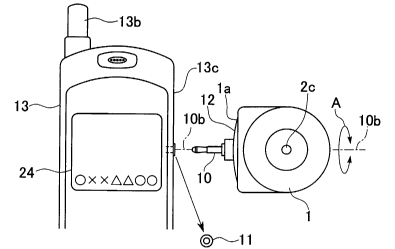
Figure 3 is a diagram to explain the connection state of the digital camera.
An earphone jack 11 is provided on the right side surface 13c of the portable
telephone 13.
A liquid crystal display section 24 is disposed on the front, and an antennae
13b
is provided on the top surface.
By inserting the plugl0 of the digital camera 1 into the earphone jack 11 in
the
direction shown in Figure 3, digital camera 1 is connected electrically to the
portable
phone 13 and is mechanically fixed in place.
The earphone jack 11 for connecting the plug 10 can be rotated 360 degrees
about
the terminal axis l Ob, as indicated by a bi-directional arrow A, because both
terminals are
circular shaped. For this reason, with reference to the front surface of the
portable
telephone 13 having the display section 13c, the lens window 2c of the digital
camera 1
can be rotated to any direction in the direction A shown in Figure 3. That is,
the lens
optical axis (image recording direction) of the digital camera 1 that
intersects the plug 10
at right angles, can be pointed to any direction within a range of rotation of
360 degrees
with respect to the liquid crystal display section 24.
Also, the mound section 12 provided on the bottom surface of the digital
camera
touches the peripheral side surface of the earphone jack 11 to slide this
section.
Accordingly, the distance of protrusion of the digital camera 1 from the
portable phone 13
can be minimized, and, the contact area to the portable phone 13 can also be
minimized.
As a result, the size of the overall apparatus can be made compact, and
sliding action to
change the recording direction of the digital camera 1 in the connected
condition about the
terminal axis IOb is facilitated.
CA 02401231 2002-08-26
WO 01/65827 PCT/JPO1/01497
Further, because the periphery section 1 a of the mound section 12 of the
digital
camera is distanced away from the side surface 13c of the portable telephone
13, if a
digital camera has a lid for the earphone jack 11, the digital camera can be
rotated without
interfering with the lid of the earphone jack 11 so that the lid does not
prevent the digital
5 camera to be seated properly.
Next, the internal circuit configuration of the digital camera 1 when it is
connected to the portable information terminal in Embodiment 1-1 will be shown
in
Figure 4. Here, the portable information terminal is represent by a portable
telephone
(including PHS) in this embodiment.
10 In the drawing, the digital camera 1 is comprised by; an imaging section
14; an
AD conversion section 15; a signal processing section 16; a buffer memory
section 17 and
an I/F (interface) section 18. In this case, the buffer memory section 17 has
a capacity to
store one sheet of image, and the memory section 20 is comprised by a
semiconductor
memory and cards and the like. It should be noted that the image data can be
output
15 directly to the portable telephone 13 without storing in the buffer memory
17.
On the other hand, the portable telephone 13 is comprised by: an I/F section
19
for transferring data between an external device connected through the
earphone jack 11; a
memory section 20 including ROM, RAM containing various programs and fixed
data, an
antennae (not shown); an RF transceiver section 21 for transferring sound
signals and
20 other data between a destination terminal through a base station; a signal
processing
section 22 primarily for processing data; an operation section having various
keys such as
those in a ten-key panel; a liquid crystal display section 24 for displaying
various data; a
switching section 25 for switching the interface section 19 according to the
type of
external device; and a CPU 26 for controlling each section by executing the
programs
stored in the memory section 20.
The interface section 19 is provided with a sound interface (I/F) 19a and an
imaging interface (I/F) 19b. The sound I/F 19a responds to analogue sound
signals input
from an externally connected device such as earphone microphone or stereo
headphone,
and converts such analogue signals to digital signals that can be processed
inside the
portable telephone and outputs the converted data to signal processing section
22, or
converts digital sound data output from the memory section 20 or signal
processing
section 22 to analogue data and outputs such data to the external device
through the
earphone j ack 11.
CA 02401231 2002-08-26
WO 01/65827 PCT/JPO1/01497
21
On the other hand, when the digital camera 1 as the external device is
connected
to the earphone jack 11, the imaging interface 19b ensures that the data
handled by the
digital camera 1 and the portable telephone 13 are compatible. That is, image
data input
from the earphone jack 11 are converted to data that can be processed by the
portable
telephone and output the processed data to the signal processing section 22,
or digital data
output from the signal processing section 22 are converted to data that can be
processed by
the digital camera 1 and output processed data to the digital camera 1 through
the
earphone jack 11.
The signal processing section 22 is a circuit specializing in processing
digitized
data such as sound data and image data at high speeds, and may be comprised by
a DSP
(digital signal processor), for example.
The liquid crystal display section 24 displays various settings of the
telephone
functions of the portable telephone and various menus as well as various
information
related to various external devices (earphone and stereo headphone and the
like) when an
external device is connected through the earphone jack.
Also, a ROM is a part of the memory and stores various programs for executing
telephone functions, control programs and various fixed data, and CPU 26
controls
various sections of the portable telephone 13 by executing such programs.
Also, a RAM
(not shown) temporarily stores data processed by the signal processing section
22, data
processed by CPU 26 and various externally input data.
The switching section 25 identifies a device when it is connected to the
earphone
jack 11, and switches to an interface appropriate to the device being
connected.
More specifically, when the switching section 25 detects that a plug is
connected
to the earphone j ack 11, it determines a device type by detecting a value of
the resistance
between the second and third contacts at the tip of the connected plug, and
determines the
device type based on this value.
In the following, the process of identifying an externally connected device by
the
switching section 22 will be explained using specific examples of connecting
the digital
camera 1, an earphone microphone, and a stereo headphone to the earphone jack
11.
Figure 7 shows an example of connecting an earphone microphone plug, and
Figure 8 shows an example of connecting a stereo headphone. The earphone plug
shown
in Figure 7 has four contacts consisting of a contact for a power supply 71, a
contact for a
ground 72, a contact for receiving sound data (a contact foi' an earphone) 73,
a contact for
CA 02401231 2002-08-26
WO 01/65827 PCT/JPO1/01497
22
transmitting sound data (a contact for a microphone) 74, and of these four
contacts, the
resistance value between the contact for the ground 72 and the contact for
receiving sound
data 73 is different than the resistance value between the contact for the
ground 72 and the
contact for transmitting sound data ?4. In contrast, the stereo headphone
shown in Figure
8 has four contacts consisting of a vacant contact 81, a contact for a ground
82, a contact
for receiving stereo (L) sound data 83, and a contact for receiving stereo (R)
sound data 84,
and of the four contacts, the resistance value between the contact for the
ground 82 and the
contact for the receiving stereo (L) sound data 83 and the resistance value
between the
contact for the ground 82 and the contact for receiving the stereo (R) sound
data 84 are
about equal. It should be noted that in the plugs of the earphone microphone
and stereo
headphone, the terminals are not insulated from each other.
Also, for the plug 10 of the digital camera 1 shown in Figure 2, the ground
section 11b is insulated from the contact for transferring the clock signal
11c so that the
resistance value between these terminal is infinite.
Accordingly, the switching section 25 detects a resistance value between
contact-
2 and contact-3, and if this value is infinite, it is determined that the
digital camera 1 is
connected, and if it is not infinite, either the earphone microphone or the
stereo headphone
is connected, so that it further detects a resistance value between the two
terminals
described above for comparison. If the result of detection shows that the
resistance values
are identical, it is determined that the connected device is the stereo
headphone and if the
detected resistance values are different, it is determined that the connected
device is the
earphone microphone.
As described above, when the switching section 25 determines that the
connected
device is the digital camera 1, the I/F section 19 selects the imaging
interface to
correspond to image data so as to enable data communication between the
digital camera 1
and the portable telephone 13 through the imaging interface 19b. Also, when
the imaging
interface 19b is selected, operation keys (not shown) provided on the
operation section 23
of the portable telephone 13 function as function keys predetermined for the
digital
camera 1. Here, image data are processed serially.
Further, in addition to its automatic ability to detect the connection by the
digital
camera 1 and selecting the imaging interface, the switching section 25
described above
may be made to identify that an external device is the digital camera 1 when
the user
performs a certain operation (mode switching, for example). Also, in this
embodiment, the
CA 02401231 2002-08-26
WO 01/65827 PCT/JPO1/01497
23
switching section 25 may be provided on the digital camera 1 side.
Figure 5 shows a flowchart for the process from the stage of preparing for
image
recording to the stage of transmitting image information.
In Figure SA, the portable telephone 13 is in the normal operational state
(5501).
In this state, the plug 10 of the digital camera 1 is inserted and coupled to
the earphone
jack 11 (5502). The current state is set to the camera mode (5503). The CPU 26
of the
portable telephone determines whether telephone operation is enabled, and if
the
telephone operation is enabled, the flow returns to 5501 (5504). If the
telephone operation
is not enabled, it determines whether the digital camera 1 is enabled (5505).
If it is not
enabled, the flow returns to 5504. If the digital camera 1 is ready to receive
image data,
image data are read-in (5506).
On the other hand, if in Figure SB, the digital camera 1 connected to the
portable
telephone performs initialization (5512), and the recorded images are
processed to output
the image data to the portable telephone 13 side through the plug 10 (5513,
5514). Then,
the flow determines whether the camera mode is in the ofd state (5515), and if
it is off, the
process is finished. In 5507 in Figure SA, the image output from the digital
camera 1 is
displayed on the liquid crystal screen of the liquid crystal display section
24. Next, flow
determines whether the user has performed the operation to store the image
(5508), and if
the store operation has been indicated, the image data are transmitted from
the digital
camera 1 through the plug 10, the earphone jack 11, and the I/F section 19 to
the portable
telephone 13 (5509), and the image data are stored in RAM of memory section 20
(5510).
Next, the flow determines whether the operation to transmit the recorded image
data
(5511), and if the transmitting operation has been indicated, the process
enters telephone
operation in 5504, and transmits the image data. If the transmitting operation
has not been
indicated, the flow returns to the normal terminal operation in 5501.
Next, an example of using the digital camera 1 by attaching it to the portable
telephone 13 will be explained. Figure 6A illustrates a case of directing the
lens window
2c of the digital camera 1 towards the recording object 27 opposing the user,
and
recording the image while the user views the image displayed on the liquid
crystal display
section 24 of the portable telephone 13. In this case, the digital camera 520
is
mechanically supported as a terminal by the portable telephone 13, so that one-
hand
operation is possible.
Also, Figure 6B illustrates a case of directing the lens window 2c of the
digital
CA 02401231 2002-08-26
WO 01/65827 PCT/JPO1/01497
24
camera 1 to the user himself holding the portable terminal apparatus attached
to the digital
camera, and recording an image of self as the recording object while the user
views the
self image displayed on the liquid crystal display section 24.
As described above, according to the present portable terminal device for
connecting the digital camera, the direction for image recording can be
changed readily by
rotating the digital camera about the plug axis.
Also, by using a dedicated extension cable 50 having an earphone jack 11' on
one
end and a plug 10' on the other end, and connecting the plug 10 of the digital
camera 1 to
the earphone jack 11' of the dedicated extension cable 50, and inserting the
plug 10' of the
dedicated extension cable 50 in the earphone jack 11 of the portable
information terminal,
the digital camera 1 can be manipulated in complete freedom. Also, by
providing a holder
31 on the digital camera 1, inserting the dedicated extension cable 50 through
a strap hole
40 provided originally on the portable information terminal and through the
holder 31 of
the digital camera 1, and inserting the plug 10' of the dedicated extension
cable 50 into the
earphone jack 11', the digital camera 1 can be attached to the portable
information
terminal to facilitate its carrying. The shape of the holder 31 are not
particularly restricted
so long as the opening is sufficiently large to permit the strap to pass
through, and such a
holder may be placed in any suitable location.
Also, in the above embodiments, by providing a knob 32 linked to the plug 10
and a guide 33 for freely movably supporting the knob 32 along the center axis
10b of the
plug 10, as shown in Figure 11, the plug 10 can be kept with the camera body.
Further, by
providing a cover for protecting the lens window 2c and linking the lens cover
to the knob
32, leans cover may be made detachable by moving the knob 32. Such an
arrangement
permits to keep the plug 10 with the camera body as well as to place the cover
over the
lens window.2c.
It is also possible to provide a sensor to detect that the digital camera 1
has been
inverted so as to invert the recorded image on the digital camera or on the
portable
information terminal.
Also, the portable information terminal may be constructed so that location
information may be attached to recorded image data by receiving such
information from a
base station to enable later to identify the location of the recorded image.
Next, the portable information terminal in Embodiment 1-2 will be explained.
In the example shown in Embodiment 1-1, the plug 10 of the digital camera 1 is
CA 02401231 2002-08-26
WO 01/65827 PCT/JPO1/01497
connected to the earphone jack 11, but in this embodiment, the earphone jack
11 is
connected to a connector of the USB (universal serial bus) cable to enable
highspeed data
transmission with personal computer and the like.
Figure 12 shows the USB cable 100 to be used in this embodiment. As shown in
this diagram, a connector 101 of the USB cable 100 has a shape to enable to
connect to the
earphone jack 11. The connector 101 has four contacts, which are arranged from
the tip
end, a first data transmit/receive contact 174, a second data transmitlreceive
contact 173, a
ground contact 172, a power supply contact 171. The USB cable is electrically
connected
and mechanically fixed to the portable telephone 13 by inserting the connector
into the
10 earphone jack 11 provided on the right side surface 13c (refer to Figure 3)
of the portable
telephone 13 from the direction shown in Figure 3. Also, by making a circular
cross
sectional shape for the connector 101, the connector 101 can be rotated 360
degrees about
the center line 101b of the connector 100 as its axis of rotation.
Here, the other connector 102 at the opposite end of the USB cable 100 is
15 connected to an upstream device such as a personal computer, and various
data exchanged
between the external device and the portable information terminal may include
sound data,
image data and text data and the like.
Also, of the contact provided on the connector 101, the ground contact 172 and
the power supply contact 173 may be left vacant if the power is not to be
supplied from an
20 external device.
Next, the internal circuit of portable information terminal in this embodiment
is
shown in Figure 13. Similar to Embodiment 1-1, the portable phone (includes
PHS) is
used as the portable information terminal.
As shown in the diagram, the portable telephone 13 has a similar structure as
the
25 portable telephone 13 shown in Figure 4 but the internal construction of
the interface
section 119 is different.
In this embodiment, the connector 101 of the USB cable 100 is connected to the
earphone jack 11 so that an interface is necessary to match the data output
from the USB
cable 100 and the data processed by the portable telephone. For this reason,
instead of the
imaging interface 19b used in Embodiment 1-1, a USB interface 19c for
converting data
output from USB cable 100 and the data processed by the portable telephone 13
is
provided in the interface section 119. And, when IJSB cable 100 is connected
to the
earphone jack 11, the switching section 125 connects output of earphone jack
11 to the
CA 02401231 2002-08-26
WO 01/65827 PCT/JPO1/01497
26
USB interface 19c, and when the earphone microphone or stereo head phone is
connected,
the output of the earphone jack 11 is directed to the sound interface 19a.
Here, the switching section 125, upon detecting that the user has operated a
certain function of the operation section 123, mode switching for example,
carries out the
process of discriminating the external device (a device connected to the
earphone jack 11,
in this case, USB cable 100). It is possible to automatically recognize an
external device
by inputting a specific signal output from an external device through the USB
cable 100
and providing a further function to the switching section 125 to recognize the
predetermined signal, which shows that the USB cable 100 is connected. In such
a case,
the specific signal should be a signal that has been predetermined for the
portable
telephone and the external device.
Next, the operation of the portable telephone 113 will be explained.
First, with the portable telephone 113 in the normal enabled state, the user
inserts
USB connector 101 into the earphone jack 11 of the portable telephone 113 to
obtain
electrical and mechanical connections, and the current state is set to USB
mode.
By so doing, a signal to report that the mode setting has been changed to USB
mode is transmitted to CPU 126 of the portable telephone 113. CPU 126,
recognizing that
the mode setting has been changed to USB mode, determines whether USB cable is
connected to the earphone jack 11. If the result indicates that such a
connection has been
made, CPU 126 outputs a signal to the switching section 126 to notify that USB
mode is
set, and the switching section 125 then selects USB interface 19c as the
output interface
for the earphone jack 11. When actual data transmission is commenced, the data
input
from the earphone jack 11 are output to the signal processing section 122
through the USB
interface 19c, and the processing section 122 processes the input data, and
the processed
data are stored as necessary in RAM in the memory section 120.
On the other hand, when an instruction is given by the user to transmit the
data
from the operation section 123 of the portable telephone 113, the signal
processing section
122 reads specified data from RAM or ROM of the memory section 120, and the
readout
data are output to USB cable through the USB interface 19c and the earphone
jack 11. By
so doing, required data can be transmitted to the external device through the
USB cable.
Next, a portable information terminal in Embodiment 1-3 will be explained. The
portable information terminal in this embodiment has the function provided for
the
portable telephone 13 described in Embodiment 1-1 as well as the function
provided for
CA 02401231 2002-08-26
WO 01/65827 PCT/JPO1/01497
27
the portable telephone 113 described in Embodiment 1-2. That is, this portable
information terminal is able to be connected to an earphone microphone, an
stereo
headphone, an digital camera l and USB cable as external devices through the
earphone
jack 11. Therefore, the portable information terminal in this embodiment is
provided with
a sound interface 19a, an imaging interface 19b and a USB interface 19c in the
interface
section 219, as shown in Figure 14, and these interfaces are switched
according to the type
of external device connected to the earphone jack 11. Accordingly, a portable
information
terminal of even higher convenience can be provided.
Next, a digital camera and a portable information terminal in Embodiment 2
will
be explained. Here, a portable telephone (includes PHS) represents the
portable
information terminal.
Figure 15 shows an illustration of a portable information terminal and a
digital
camera in Embodiment 2. In this illustration, a reference numeral 510 relates
to the
portable telephone and a reference numeral 520 relates to the digital camera.
The digital camera 520 has a lens window 522 in the center section of the
camera
body 521, and a plug 523 protrudes from the bottom surface 521a that
intersects the
optical axis of the lens (not shown) inside the lens window 522, for example.
The plug
523 has two contacts, contact for transferring a clock signal 525a and a
contact for
transmitting data 525b, or in addition to these two contacts, a third contact,
a contact for
receiving data 525c, is provided.
The portable telephone 510 has a display section 510 such as a liquid crystal
display on the telephone body 511, an antennae 513, a jack 514 on a side
surface 511a.
The jack 514 is provided with two contacts, one for receiving data and another
for
transferring a clock signal to correspond to the plug 523 of the digital
camera 520
described above, or in addition to these two contacts, a third contact, for
transmitting data.
Here, it is preferable that the earphone microphone jack provided on an
existing portable
telephone is used for the jack.
When the plug 523 of the digital camera 520 is inserted into the earphone jack
514 of the portable telephone 510, the contacts of the plug 523 and the jack
414 contact
other contacts of the same kind at specific insertion locations to enable to
transfer signals.
Accordingly, a portable combined digital cameralinformation terminal system is
provided
comprised by the portable telephone 510 and the digital camera 520 connected
mechanically and electrically.
CA 02401231 2002-08-26
WO 01/65827 PCT/JPO1/01497
28
Next, the circuit configuration of the portable digital camera connecting
apparatus will be explained with reference to Figure 16.
As shown in Figure 16, the portable telephone 510 is comprised by: an I/F
interface section S 10a for transferring data with an external device; a
memory section
S l Ob for storing various data; an RF processing section 5 l Oc for
processing data through
an antennae; a signal processing section S 10d for processing transmit/receive
signals; and
an operation section S 10e comprised by a 10-key board and function keys and
others to be
operated by the user; a display section 512 served by a liquid crystal display
section S l Of;
and a control section 5 log for controlling various sections of the portable
telephone 510;
and further, a jack having a contact for transferring a clock signal 527a for
transferring
various data with the external device; and a contact for receiving data 527b
for receiving
data. Further, by providing a contact for transmitting data 527c for
transmitting data in the
earphone jack 514, data may be transmitted to the external device as required.
The control section 510 is structured as a logic circuit operated primarily by
a
microcomputer, and comprises CPU, ROM, RAM and the like. CPU executes certain
computations according to predetermined programs. ROM stores control programs
and
control data required for executing various programs by CPU, and similarly RAM
is used
to temporarily store and output various data required for the CPU to execute
various
computations.
The digital camera 520 is comprised by: an imaging section 520a having an
imaging element such as CCD (charge coupled device); an AD conversion section
520b
for converting image data produced by analogue signals to digital signals; a
control
section 520c for controlling various sections of the digital camera 520 and
processing
image data; an I/F section 520e for transferring data to and from the buffer
memory
section 520d that stores image data, as well as to and from an externally
connected device;
a contact for transferring a clock signal 525a; and a contact for transmitting
data 525b.
The buffer memory 520d has a capacity to store one sheet of image, and the
memory
section 510b comprises a semiconductor memory and cards and the like.
The control section 520c is structured as a logic circuit operated primarily
by a
microcomputer, and comprises CPU, ROM, RAM and the like. CPU executes certain
computations according to predetermined programs. ROM stores control programs
and
control data required for executing various programs by CPU, and similarly RAM
is used
to temporarily store and output various data required for the CPU to execute
various
CA 02401231 2002-08-26
WO 01/65827 PCT/JPO1/01497
29
computations.
Also, corresponding to the earphone jack 514 of the portable telephone, the
plug
523 is constructed with two contacts, contact for transferring a clock signal
525a and a
contact for transmitting data 525b, but by further providing a contact for
receiving data
525c transmitted from an external device may be received.
Next, when the plug of the digital camera 520 is inserted into the jack of the
portable information terminal 510 thereby connecting the two electrically, the
processes
are earned out by both the portable information terminal 510 and the digital
camera 520,
which will be described with reference to Figures 1721.
First, a case will be described with reference to Figures 17, 18, in which
there are
two contacts between the portable telephone and the digital camera 520, that
is, the
portable telephone 510 has the contact for transferring a clock signal 527a
and the contact
for receiving data 527b and the digital camera 520 has the contact for
transferring a clock
signal 525a and the contact for transmitting data 525b. In this case, two
possibilities exist,
one is to supply a clock signal from the digital camera 520 and other is to
supply a clock
signal from the portable telephone 510.
<Digital camera supplies a clock signal>
First, Figure 17 shows a timing chart for a clock signal and corresponding
output
data when the portable telephone 510 and the digital camera 520 are
electrically connected
and the a clock signal is supplied from the digital camera 520 side to the
portable
telephone 510 side.
As shown in these diagrams, when the plug 523 of the digital camera 520 is
connected at time t0 to the earphone jack 514 of the portable telephone 510 so
that the two
are connected electrically, the control section 520c inside the digital camera
520 outputs a
clock signal from the contact for transferring the clock signal 525a (refer to
Figure 17A),
and arbitrary data are output from the contact for transmitting data 525b
(refer to Figure
17B).
According to such a process, a clock signal is input in the control section S
l Og of
the portable telephone 510 through the contact for transferring the clock
signal 527 and
the I/F section S 10a, and arbitrary data are input through the contact for
receiving data
527b and the I/F section S 10a. In this case, arbitrary data refer to any
random data, not to
the data that are specifically prearranged between the digital camera and
portable
telephone.
CA 02401231 2002-08-26
WO 01/65827 PCT/JPO1/01497
Then, upon detecting the clock signal and data, the control section S l Og
determines that the external device being connected at this time is the
digital camera 520,
and the control section S l Og stores image data output from the digital
camera and input by
way of the contact for transmitting data 525b, 527b in the memory section S l
Ob inside the
5 portable telephone 510, and displays the image received on the liquid
crystal display
section S l Of.
Here, image data after being stored in the memory section 5 l Of of the
portable
telephone 510 can freely be displayed on the liquid crystal display section S
l Of or deleted
by the user performing certain operations using the operation section 510e.
10 <Portable telephone 510 supplies a clock signal >
Next, Figure 18 shows a timing chart for a clock signal and corresponding
output
data when the portable telephone 510 and the digital camera 520 are
electrically connected
and the clock signal is supplied from the portable telephone 510 side to the
digital camera
520 side.
15 As shown in these diagrams, when the plug 523 of the digital camera 520 is
connected at time t0 to the earphone jack 514 of the portable telephone 510 so
that the two
are connected electrically, the control section 520c inside the digital camera
520 is
supplied with a clock signal through the contact for transferring a clock
signal 527a of the
portable telephone 510 and the contact for transferring a clock signal 525a
and the IlF
20 section 520e of the digital camera (refer to Figure 18A).
Upon receiving the clock signal, the control section 520c inside the digital
camera 520 outputs data of predetermined format from the data line section
525a. For
example, if "AA55" is set as such formatted data,, the digital camera 520
outputs signals
shown in Figure 21 to the portable telephone 510 through the contact for
transmitting data
25 525a. Specifically, the control section 520c outputs predetermined data in
"AA55" format
to the portable telephone 510 in synchronization with the input a clock
signal.
Accordingly, data of a specific format is input into the portable telephone
510 through the
data line section 527b and the I/F section S 10a.
In the above description, predetermined data are not limited to 8-bit data
30 described above, but may include any type of data so long as the data can
be matched
between the portable telephone 510 and the digital camera 520.
If the data obtained by the control section S l Og is the predetermined data,
it
determines that the external device being connected at this time is the
digital camera 520,
CA 02401231 2002-08-26
WO 01/65827 PCT/JPO1/01497
31
and stores image data transmitted from the digital camera 520 through the data
line
sections 525b, 527b in the memory section S l Ob of the portable telephone
510, and
displays received image data on the liquid crystal display section S l Of.
Here, image data after being stored in the memory section 5 l Ob of the
portable
telephone 510 can freely be displayed on the liquid crystal display section S
l Of or deleted
by the user performing certain operations using the operation section S 10e.
On the other hand, when data dii~erent than the predetermined format are input
or
no data are input, it is determined that the external device being connected
at this time is
not the digital camera.
The next case will be an example in which the portable telephone 510 and the
digital camera 520 are connected through three contacts. That is, the portable
telephone
510 has a contact for transferring a clock signal 527a, a contact for
receiving data 527b
and a contact for transmitting data 527c, while the digital camera 520 has a
contact for
transferring a clock signal 525a, a contact for transmitting data 525b and the
contact for
receiving data 525c.
Here, in this case also, there are two ways of supplying the a clock signal:
the
digital camera 520 side supplies a clock signal or the portable telephone 510
side supplies
a clock signal.
<Digital camera supplies a clock signal>
Figure 19 shows a timing chart for a clock signal and corresponding output
data
when the portable telephone and the digital camera are electrically connected
and the a
clock signal are supplied from the digital camera to the portable telephone.
As shown in these diagrams, when the earphone jack 514 of the portable
telephone 510 is connected at time t0 to the plug 523 of the digital camera
520 so that the
two are connected electrically, the contact for transferring a clock signal
520c inside the
digital camera 520 outputs a clock signal from the contact for transferring a
clock signal
525a (refer to Figure 19A), arbitrary data are output from the contact for
transmitting data
525b (refer to Figure 19B).
According to such a process, a clock signal are input in the control section S
l Og
of the portable telephone 510 through the contact for transferring a clock
signal 527 and
the I/F section S 10a, and arbitrary data are input through the contact for
receiving data
527b and the I/F section S 10a. In this case, arbitrary data refer to any
random data, not the
data that have been pre-arranged between the digital camera and portable
telephone.
CA 02401231 2002-08-26
WO 01/65827 PCT/JPO1/01497
32
Then, when the control section S l Og detects the clock signal and the data,
it
determines that the external device being connected at this time is the
digital camera 520,
and selects a circuit in the I/F section S 10a to correspond to the image
signals, and
switches circuits.
When the imaging circuit is selected, operation keys and the like provided on
the
operation section 510e of the portable telephone 510 function as predetermined
function
keys for the digital camera 520.
Then, when the user operates the operation section S 10e as keys for the
digital
camera, the control section S l Og transmits signals corresponding to the
operation to the
digital camera 520 through the contact for transmitting data 527c (refer to
Figure 19C).
Then, the control section 520c inside the digital camera 520 can perform
various processes
corresponding to the operational data to execute the processes specified by
the portable
telephone 510 of the digital camera 520.
<Portable telephone 510 supplies a clock signal>
Next, Figure 20 shows a timing chart for a clock signal and corresponding
output
data when the portable telephone and the digital camera are electrically
connected and the
a clock signal are supplied from the portable telephone to the digital camera.
As shown in these diagrams, when the plug 523 of the digital camera 520 is
connected at time t0 to the earphone jack 514 of the portable telephone 510 so
that the two
are connected electrically, the control section 520c inside the digital camera
520 is
supplied with a clock signal through the contact for transferring a clock
signal 527a of the
portable telephone 510, the contact for transferring a clock signal 525a of
the digital
camera and the I/F section 520e (refer to Figure 20A).
Upon receiving the clock signal, the control section 520c inside the digital
camera 520 outputs data of predetermined format from the data line section
525a (Refer to
Figure 20B). For example, if "AA55" is selected as such formatted data, the
digital camera
520 outputs signals shown in Figure 21 to the portable telephone 510 through
the contact
for transmitting data 525a. Accordingly, data of a specific format is input
into the
portable telephone 510 through the data line section 527b and the I/F section
S 10a.
Then, when the control section 510g determines the data, and if the data
matches
predetermined data, it is determined that the external device being connected
at this time is
the digital camera 520, and selects a circuit in the I/F section S 10a to
correspond to the
image signals, and switches circuits.
CA 02401231 2002-08-26
WO 01/65827 PCT/JPO1/01497
33
When the imaging circuit is selected, operation keys and the like provided on
the
operation section 5 10e of the portable telephone 510 function as
predetermined function
keys for the digital camera 520.
Then, when the user operates the operation section 510e as keys for the
digital
camera, the control section S l Og transmits signals corresponding to the
operation to the
digital camera 520 through the contact for transmitting data 527c (refer to
Figure 20C).
Then, the control section 520c inside the digital camera 520 can perform
various processes
corresponding to the operational data to execute the processes specified by
the portable
telephone 510 of the digital camera 520.
On the other hand, when data dii~erent than the predetermined format are input
or
no data are input, it is determined that the external device being connected
at this time is
not the digital camera, and the control section S l Og does not perform any
specific
processes.
Next, a portable information terminal and a digital camera for connecting to a
portable information terminal in Embodiment 3 will be explained. this
embodiment will be
exemplified using a portable telephone (includes PHS) as a portable
information terminal.
Figure 22 shows a block diagram of the configuration of the portable
information
terminal and the digital camera for connecting to a portable information
terminal.
In the diagram, the portable telephone 630 stores or displays as necessary
image
data received from the digital camera 650 though a specific signal line. On
the other hand,
the digital camera 650 is operated by the power supplied from the portable
telephone 630,
and transmits recorded image data to the.portable telephone 630 through a
specific signal
line. The portable telephone 630 and the digital camera 650 are connected by
signal lines
Lla~Llc, which are: a power line Lla for supplying power from the portable
telephone
630 to the digital camera 650; a data request signal line Llb for outputting a
request signal
for image data from the portable telephone 630 to the digital camera 650; and
a data
output signal line Llc for outputting (transmitting) a transmit-ready signal
and image data
from the digital camera 650 to the portable telephone 630. Here, the signal
lines Lla~Llc
are connected to the earphone jack Jl of the portable telephone 630.
Next, the structure of the portable telephone 630 will be explained.
The telephone control section 602 has a function (terminal detecting section)
to
detect a transmit-ready signal to show readiness for transmitting image data
output from
the digital camera 650 through the data output line Llc; a function Llb
(terminal side
CA 02401231 2002-08-26
WO 01/65827 PCT/JPO1/01497
34
output section) to output a transmit-request signal to the digital camera 650
through the
data request signal line; and a function (receiving section) to receive image
data
transmitted from the digital camera 650 through the data output signal line
Llc. Also, the
telephone control section 602 controls onloff of power supplied to the digital
camera 650
through the power line Lla. Further, the telephone control section 602
controls various
section of the portable telephone 630. The telephone control section 602 is
comprised by
CPU, for example, and performs its functions by executing various programs for
actualizing the function pre-stored in the memory section containing ROM and
the like.
The memory section 604 is a memory for storing information related to various
functions of the portable telephone 630, and stores telephone numbers
according to
telephone book function or image data received from the digital camera 650
under the
control of the telephone control section 602.
The display section 606 displays operational states of various functions of
the
portable telephone 630, and displays for viewing as required, such information
as
telephone number of the transmitter and reception conditions at receiving
times, residual
battery power, and image data received from the digital camera 650.
The power section 608 supplies power to various sections of the digital camera
650 and its on/off function of the power is controlled by the action of the
telephone control
section 602.
The operation section 610 is used to execute various functions when using the
phone or receiving image data from the digital camera 650, and is provided
with
alphanumeric keys for entering numbers and characters, and menu keys (not
shown) to
select various functions. Also, the radio section 670 is used to provide the
telephone
function for the portable telephone 630, and comprises a radio section 670a
for processing
radio signals, a speaker 670b, and a microphone 670c. The structure of the
radio section
670 is the same as conventional portable telephone, and detailed explanations
are omitted.
Next, the structure of the digital camera 650 will be explained.
The camera control section 622 is provided with: a function (camera side
output
section) to forward a transmit-ready signal to show that image data are ready
to be
transmitted to the portable telephone 630 through the data output signal line
Llc; a
function (camera side detection section) to detect a transmit-request signal
to request
image data to be transmitted from the portable telephone 630 through the data
request
signal line Llb; a function (transmitting section) to transmit image data to
the portable
CA 02401231 2002-08-26
WO 01/65827 PCT/JPO1/01497
telephone 630 through the data output signal line Llc. Also, the control
section 622
controls various sections of the portable telephone 630. The camera control
section 622 is
comprised by a CPU, for example, and performs its function by executing
various
programs pre-stored in ROM and the like to actualize the functions of the
camera control
5 section 622.
The memory 624 stores image data recorded by the digital camera 650
successively, and the image data are stored successively as pictures, for
example. Also, the
imaging section 626 comprises imaging functions of the digital camera 650, and
is
provided with a lens and CCD (not shown) and the like, and records an image of
the
10 recording object under the direction of the camera control section 622. An
image recorded
by the imaging section 626 is processed by the camera control section 622, and
is stored in
the memory 624 as image data. Also, the digital camera 650 can record images
automatically at given intervals under the direction of the camera control
section 622, for
example, and stores image data in the memory 624, and refreshes image data at
the given
15 intervals.
Next, the process of transmitting image data from the digital camera 650 to
the
portable telephone 630 will be explained. Figure 23 shows a timing chart for
transmitting
image data from the digital camera 650 to the portable telephone 630. Image
data S1 is
comprised by a bulk image data equivalent to one picture of the digital
camera, a header
20 and an end marker. In this diagram, when a specified source voltage P [V]
is supplied
from the portable telephone 630 to the digital camera 650 through the power
line Lla (at
time t0), the digital camera 650 begins its operation, and the camera control
section 622
changes the state of the output signal line L1c from a high impedance state
(Hiz) to the
H(igh)-state. By so doing, the digital camera 650 informs portable telephone
630 that it is
25 preparing to transmit image data. At this time, the camera control section
622 initializes
each section of the digital camera 650, and then processes a first picture
recorded by the
imaging section 626 (includes the process of writing image data in the memory
624) (an
interval MO). During the interval M0, the data output signal line Llc (1) is
maintained in
the H-state. When the above processing is finished, the camera control section
622
30 changes the data output signal line Llc to the L(ow)-state, where L section
signal
transmit-ready signal (time t1). By so doing, the portable telephone 630 is
notified that
image data transmitting preparation is completed.
The telephone control section 620 detects the L-state of the data output
signal line
CA 02401231 2002-08-26
WO 01/65827 PCT/JPO1/01497
36
Llc, and outputs a specific signal successively to the digital camera 650,
through the data
request signal line Llb (time t2). Such a signal may be a clock signal
(transmitting request
signal) C 1 corresponding to a bit count of the image data S 1. When clock
signal C 1 is not
being output, the data request signal line Llb is normally set in the L-state
by the
telephone control section 602.
Responding to the clock signal C1, the camera control section 622 successively
reads image data S 1 stored in the memory 624 and outputs them to the data
output signal
line Llc. When image data S1 corresponding to one picture is output, the
camera control
section 622 returns the data output signal line L 1 c to the H-state (time t3
), and informs the
portable telephone 630 that it is in the image data transmitting preparation
state. At this
time, the camera control section 622 performs image processing of a second
picture
recorded by the imaging section 622 (includes writing image data for one
picture into
memory 624) (interval Ml). When the above process is finished, the camera
control
section 622 changes the data output signal line Llc to the L-state (time t4).
By so doing,
the portable telephone 630 is notified that image data transmitting
preparation is
completed. Henceforth, the processes between tl~t4 are repeated, and image
data are
transferred as needed. Accordingly, the camera control section 622 transmits
image data in
picture terminals, and image data are output after the transmit-ready signal
(L-state for the
data output signal line Llc) is issued, in response to the clock signal from
the telephone
control section 602.
The telephone control section 602 successively receives image data output to
the
data output signal line L1c and writes the data into the memory 604, and when
image data
corresponding to one picture are written into the memory 604, displays the
image data on
the display section 606 for viewing. Also, if the image data from the digital
camera 650
are to be stopped, the telephone control section 602 stops supplying the
specified source
voltage P [V] to the digital camera 650 (time tx) to stop the operation of the
digital camera
650 so as not to receive any more image data. By so doing, the portable
telephone 630
does not supply power to the digital camera so that it is possible to prevent
wasting the
battery of the portable telephone 630.
On the other hand, if the portable telephone 630, for example, receives mail
during image data reception, the telephone control section gives priority to
mail reception
so that transmitting of clock signal C2 is temporarily suspended (~Ma, ~Mb),
and the
clock signal C2 is divided into clock signals C2a~C2c and are output. In
response to
CA 02401231 2002-08-26
WO 01/65827 PCT/JPO1/01497
37
interruption of the clock signal C2, the camera control section 622 interrupts
outputting of
image data S2 (OMa, ~Mb). And, when outputting of clock signal C2 is resumed
beginning with the clock signal (C2b and then C2c) that follows clock signal
(C2a) that
was transmitted just before the interruption, and in response, the camera
control section
622 successively outputs image data S2 (S2b, S2c) that follows data (S2a) that
was
transmitted just before the interruption. According to this procedure, even
when the
telephone control section 602 interrupts outputting of clock signal C2
temporarily in order
to perform a task other than image data acquisition, interrupted image data S2
can be
received in continuation by resuming to output the clock signal C2.
Also, when the camera control section 622 renews (overwrites) the stored image
data in
the memory 624 at given intervals (0.2 seconds, for example) with the latest
image data, if
the interruption interval (~lVla, OMb) becomes longer than the renewing
interval of image
data, then, during this interval, image data in the memory 624 are renewed by
the latest
image data. In such a case, a problem is created that the image data output
from the
camera control section 622 according to re-starting of outputting clock signal
C2 by the
telephone control section 602 are different than the image before the clock
signal
interruption. Therefore, in such a case, the camera control section 622
changes the data
output signal line Llc to the H-state, and notifies the portable telephone 630
that it is in
the image data transmitting preparation state. In the meantime, the telephone
control
section 602 detects a transmit-ready signal, and interrupts the process of re-
starting
reception of the interrupted image data S2 (re-starting clock signal C2
output). Then, when
it detects a signal to show the transmitting allowed state (L-state of the
data output line
Llc), the telephone control section 602 is permitted to perform normal image
data
receiving process carried out during the interval tl~t4. By adopting such a
procedure, it is
possible to re-start image data reception without any difficulty, when the
clock signal from
the digital camera 650 has been interrupted longer than the image renewing
interval of the
digital camera 650.
The structure of the image data (frame) will be explained with reference to
Figure
24. In this diagram, image data S1 is comprised by a bulk image data 400b
equivalent to
one picture recorded by the digital camera 650 and a header 400a containing
attributes for
one picture and an end marker 400c to show the tail end of the image data S 1.
The relationship between a clock signal output and output timing of image data
will be explained with reference to Figure 25. In this diagram, each bit data
that constitute
CA 02401231 2002-08-26
WO 01/65827 PCT/JPO1/01497
38
image data S 1, i. e., S 1 [0], S 1 [ 1], . . . S 1 [n], where n is an
integer, is output in response to
the rise instant t2 [0] (t2[0]=t2), t2[1], ... t2[n] of clock signal C1. Also,
an interval M2 is
a time interval between the rise instant t2[n] of the clock signal C 1 to the
output time of
each bit data S 1 [n] of image data S 1, an interval M3 is the width of the
clock signal C 1 in
the H-state, and an interval M4 (MS) is a period of one cycle of the clock
signal C1
(frequency). Also, clock signal C 1 is output at a constant interval, but the
period may
sometimes vary between M4~M5, depending on the processing state of the
telephone
control section 602. In such cases, output timing of bit data S 1 [n] of the
image data S 1
also varies accordingly (S 1 [ 1 ]~S 1 [2]).
Here, the structure of the header 400a is as shown in Figure 26. For example,
the
header 400a is comprised of 32 bytes to indicate such items as: rdummy~ for
detection of
abnormality in the received data to be described later; rimage data start
acknowledge;
bulk image data attributes such as rimage width and image height and the like.
Here, so long as the clock signal from the telephone control section 602 is
not
interrupted, the camera control section 622 transmits data for each item of
the header 400a
as a whole as image data S 1 (Figure 24). By so doing, handshake operation
(steps for
exchanging commands to confirm that transmitter and receiver are both in a
state to begin
transmit/receive operations), that has been necessary for each item of the
header in the
past, can now be performed in one step, so that the time required for
handshake operation
can be shortened.
Also, the telephone control section 602 is able to detect abnormality in the
received image data by checking the items in the header 400a of the image data
S 1, such
as ~dummy~ data and rimage data start acknowledged data with predetermined
values. For
example, if rdummy~ data of the received image data is "552A" (hexadecimal),
it is
different than a fixed value "AA55" (hexadecimal) so that it is detected as
abnormal.
Figure 27 shows an example of the data value of 2-byte end marker 400c. In
this
diagram, the end marker has its data value as "FFD9" (hexadecimal) and is the
data to
show the tail end of the image data S 1.
Figure 28 shows an example of the output sequence of the image data S 1. In
this
diagram, following the header 400c, bulk image data 400b are transmitted
successively
and the end marker 400c is transmitted last.
Here, the digital camera 650 in this embodiment may be mounted directly on the
portable telephone 630 so as to terminal the two terminals. In such a case,
there is no need
CA 02401231 2002-08-26
WO 01/65827 PCT/JPO1/01497
39
for a connecting cable, and provides an advantage of convenience of use.
Also, the above embodiment represent an example of the use of clock signal to
request image data to be transmitted from the portable information terminal to
the digital
camera, but data transmission technique is not limited to this case. For
example, after
notifying the portable information terminal of readiness to transmit image
data from the
digital camera, image data may be transmitted at suitable times from the
digital camera.
By so doing, the data request signal line between the portable information
terminal and the
digital camera becomes unnecessary to facilitate mutual connectivity, and to
enable to
reduce manufacturing cost by reducing the signal lines for connectors and
cables. Also,
the contents of header and end marker comprising the image data (frames) may
be varied
suitably depending on the type, function and portability of the digital camera
and portable
information terminal.
Next, a portable information terminal in Embodiment 4 will be explained. Here,
a
portable telephone (includes PHS) is used as an example of the portable
information
terminal.
Figure 29 shows an electrical configuration of the portable information
terminal
in this embodiment. In the diagram, portable telephone 700 is comprised by: an
antennae
(not shown); an RF processing section 701 for processing sound signals and the
like with
the responding terminal through a base station; a signal processing section
702; an
operation section 704 having various keys such as a ten-key section; a display
section 706
for displaying various data; a ROM 708 for storing various programs and fixed
data; a
RAM 716; an external memory interface section 710; a CPU 712 for overall
control of
various sections; and a portable terminal interface section 714.
The signal processing section 702 is a circuit to perform functions such as
encoding and decoding of sound signals, modulating received signals decoded in
the RF
processing section 701, outputting to a speaker (not shown), and encoding
sound signals
for sound call input from a microphone (not shown) and outputting to the RF
processing
section 701.
As shown in Figure 30, the operation section 704 provided in the portable
telephone body 700A is provided with various keys such as: a start key to
receive a call;
an end key to end a call; numeric keys (also for alphabets); a ten-key section
704A that
includes #-key, *-key and other code keys; F-key for setting functions; a
power-key for
turning power on/of~; a clear key for clearing settings; a mail-dispatch key
for mailing
CA 02401231 2002-08-26
WO 01/65827 PCT/JPO1/01497
request and others.
The display section 706 displays settings and menu information for providing
telephone functions of the portable information terminal 700, and image
information such
as recording parameters to be used when the camera 800 is connected to the
portable
5 information terminal.
ROM 708 stores various programs for providing the telephone function and
control programs as well as various fixed data.
RAM 716 stores temporary data processed by CPU 712 and various data input
externally through the external memory interface section 710.
10 The camera 800 is comprised by: a digital camera 801 and a digital camera
interface section 802, and can be connected to the portable telephone 700
using the
earphone jack provided conventionally for the portable telephone 700. Figure
29 shows a
block diagram of the portable telephone 700 connected to the camera 800, and
the clock
signal is supplied from the camera 800 to the portable telephone 700 side
through the
15 control line 730, and the control line 731 transmits control data from the
portable '
telephone 700 side to the camera 800, and the signal Iine 732 transmits image
data
recorded by the digital camera 801.
Control operations for switching the operational mode is performed by CPU 712,
and this process will be explained with reference to the flowcharts shown in
Figures 31,
20 32. The portable telephone 700 has two operational modes, sound mode and
recording
mode. The sound mode is the operational mode used when the portable telephone
700
operates as a telephone, and the recording mode enables image recording when
the camera
is connected to the portable telephone 700, by operating the keys of the
operation section
704 of the portable telephone 700.
25 When the power key in the operation section 704 is operated, in Figures 31,
32,
operational mode of the portable telephone 700 is set to the sound mode and
the telephone
function is enabled (step 5300). Next, in step 5301, it is determined whether
the camera
800 is connected to the portable telephone 700. The discrimination process for
the
connection of camera 800 may be made by providing a detection device to detect
the
30 connection of connector to the earphone jack of the portable telephone 700,
and a
detection signal is accessed and used for the determination. Or, the
determination may be
made according to whether a signal, to be output from the digital camera 801
of the
camera 800 to the portable telephone 700 side through the digital camera
interface section
CA 02401231 2002-08-26
WO 01/65827 PCT/JPO1/01497
41
802, has been output or not. It is of course permissible to use other methods.
If it is determined in step 5301 that the camera 800 is not connected to the
portable telephone 700, the flow advances to step 5312, and the process is
terminated
leaving the setting in the sound mode.
Also, if in step 5301, it is determined that the camera 800 is connected to
the
portable telephone 700, then, in step 5302, it is determined whether a key in
the operations
section 740 normally specified for communication function (telephone function
in this
embodiment) of the portable telephone 700 has been operated. In this
embodiment, this
key is assumed to the F-key, for example.
The F-key is normally used in combination with numeric keys for a specific
function of the telephone functions, but it is assumed in this case that the F-
key is assigns
for switching the sound mode to the recording mode when the camera 800 is
connected to
the portable telephone 700. If it is determined, in step 5302, that the F-key
as the mode
switching key has been operated, and further in step 5303, it is determined
whether or not
the F-key has been pressed for the long-press that requires the key to be
pressed for a
specific duration. If it is determined, in step 5302, that the F-key has not
been operated,
and in step 5303, that the F-key has been pressed for the short-press that
requires the key
to be pressed for a shorter duration than the specific duration, then the flow
advanced to
step 5312, and the process is terminated with the setting remaining in the
sound mode.
In step 5303, if it is determined that the F-key has been pressed for the long-
press
that requires the key to be pressed for the specific duration, the flow
changes to the
recording mode that permits the camera 800 to be operated by the keys in the
operation
section 704 of the portable telephone 700 (step 5304). At this point,
reflected light from
the recording object is received in the recording section (not shown) of the
digital camera
801, and is converted into image data in the recording section to correspond
to the
brightness of the recording object, and the image data of the recording object
are output
from the signal line 732 to the portable telephone 700 side, through the
digital camera
interface section 802, in synchronization with the clock signals output from
the control
line 730. CPU 712 accesses the image data through the portable terminal
interface section
714, and transmits the image data to the display section 706.
The result is that the image based on the image data output from the digital
camera 801 is displayed on the display section 706 of the portable telephone
700 (step
5305). Continuing, in step 5306, it is determined whether the F-key has been
pressed for
CA 02401231 2002-08-26
WO 01/65827 PCT/JPO1/01497
42
mode change. If it is determined, in step 5306, that the F-key has been
operated, it is
determined in step S307 whether the F-key has been pressed for the short-
press. If it is
determined that the F-key has been pressed for the short-press, this key
functions as the
shutter key, and the digital camera 801 records an image of the recording
object (step
5308), and the recorded still image is displayed on the display section 706
(step 5309).
On the other hand, if it is determined, in step 5307, that the F-key has been
pressed for the long-press, the mode is shifted from the recording mode to the
sound mode
(step 5313), the process is terminated. The state of the portable telephone
700 in the sound
mode corresponds to a certain state demanded by a state of input-key. Here, a
certain state
relates to a state enabled by an input-key such as a start call operation,
parameter settings
for telephone function or data communication function, composing mails and
telephone
number entries.
After the still image recorded in step 5309 is displayed on the display
section 706,
it is determined whether the recording process is finished (step 5310). This
determination
may be based on assigning the finish-key in the operation section 704 as the
end-recording
key when the recording mode is active, and the determination is made according
to
whether or not the finish-key has been operated.
If it is determined, in step 5310, that the recording process is finished, the
flow
changes to the sound mode (step 5311), and this process is terminated. Or, if
it is
determined, in step 5310, that the recording process is not finished, the flow
returns to
step 5306, and the process described above is repeated.
Here, the portable information terminal in this embodiment may be operated in
such a way that when a mail is received while the terminal is in the recording
mode, the
mode changes to mail receive mode.
Also, in this embodiment, a certain key in the operation section 704 assigned
normally to the telephone function is used as the mode switching key for
switching
between the sound mode and the recording mode when the camera 800 is connected
to the
portable telephone 700, and furthermore, when the terminal is in the recording
mode, this
key is used as a function key to provide functions related to recording
operations, for
example, the shutter key, however, instead of assigning only one key to
functions related'
to recording operations, several different keys may be assigned to functions
related to
image recording.
Also, in this embodiment, shutter key is selected to represent a function
related to
CA 02401231 2002-08-26
WO 01/65827 PCT/JPO1/01497
43
image recording operations, but it is not limited to such a choice and the key
may be
assigned to perform other functions such as zoom operation or setting
recording
conditions.
Further, before or after changing to the recording mode, switching from the
sound
S mode and the recording mode, or from the recording mode to the sound mode
may be
carried out by either the short-press method or the long-press method, so long
as such an
operation can be distinguished from other operations.
The present invention has been embodied by examples shown above with
reference to the diagrams, however, specific structures are not limited to
these examples,
and designs without departing from the essence of the present invention are
included.
For example, in Embodiments 1-1~1-4, portable telephone (includes PHS) was
used to represent a preferred portable terminal device, but it is not limited
to this case, so
that any terminal is acceptable so long the terminal can be connected to
portable personal
computers, electronic notebooks and digital cameras.
INDUSTRIAL APPLICABILITY
According to a first aspect of the portable information terminal, two contact
points are provided for transmitting and receiving data, and thus the
connectors of a USP
cable comprising the same structure can be connected. Thereby, carrying the
conventionally required PC card is no longer necessary, and a useful portable
information
terminal can be provided. Furthermore, data communication between the portable
information terminal and a personal computer becomes possible without using an
insertion
slot for a PC card, and thus other peripheral devices can be operation in
parallel on the
personal computer side.
According to a second aspect of the portable information terminal, a power
supply
contact and a ground contact are provided, and thus an external power supply
becomes
possible. As a result, the electrical consumption of the portable telephone
can be
reduced.
According to a third aspect of the portable information terminal, the contacts
of the
jack are arranged in order of, from an inner side towards an outer side of the
terminal body,
the data transmission-reception contact, other data transmission-reception
contact, the
ground contact, and the power supply contact, thus avoiding the problem of a
poor contact
even when a case section having a large contact area is rotated completely so
as to serve as
CA 02401231 2002-08-26
WO 01/65827 PCT/JPO1/01497
44
the voltage part. In addition, power shorting can be avoided because there is
no nearby
contact, even during partial insertion. In particular, the arrangement of the
power supply
contact and the ground contact conform to the arrangement of the earphone jack
contacts,
and thus there is the advantage of preventing trouble on the terminal side.
According to a fourth aspect of the portable information terminal, there is no
need
to provide a new connector for a USB cable connection because an earphone jack
provided on any existing portable information terminal can be used as a data
communication terminal. As a result, the effects can be attained that the
miniaturization,
lightening, and cost reduction of the portable communication terminal can be
realized, and
at the same time, a useful portable information terminal can be provided. In
addition,
because the earphone jack can be rotated 360 degrees, there is no need to
confirm the
orientation of the insertion when the USB connector is inserted, which is
useful.
Furthermore, because a lock mechanism is not provided, the lock can be
released without
worry.
According to a seventh aspect of the portable information terminal, in the
jack
terminal, the first data transfer contact namely data transmission-reception
contact can be
used as a data line contact and the second data transfer contact namely data
transmission-
reception contact can be used as a clock line contact, and thus the earphone
microphone
can be used to transfer image data produced by the digital camera, which
contributes to
making possible a multi-purpose portable information terminal. Thereby, the
effect is
attained that a portable information terminal can be provided that is
responsive to the
diversification of the user's needs and has a high usability.
According to an eleventh aspect of the portable information terminal, a
circuit
switching section that connects the jack to a sound circuit or a data
processing circuit is
provided, and thus, depending of the external devices connected to the jack,
the circuit that
handles the input and output data is switched, and thereby data processing
appropriate to
the external devices can be carried out. Thereby, even with external devices
that process
different data, a connection can be made using one jack.
According to a sixteenth aspect of the portable information terminal, when the
connecting of a USB cable has been detected, the switching circuit
automatically switches
the contact destination of the earphone jack depending on the connected
device, and thus
processing according to the various data output from the earphone jack can be
carried out.
According to the seventeenth aspect of the portable information terminal, a
jack is
CA 02401231 2002-08-26
WO 01/65827 PCT/JPO1/01497
provided that has four contacts for a power supply, a ground, transferring a
clock signal
and transferring data, and thus by inserting the plug of the digital camera
into the jack, it
can be installed by being directly connected mechanically and electrically.
Thereby, a
power supply can be received from the portable information terminal, image
recording
5 carried out, and the recorded images can be sent to the portable information
terminal.
According to the eighteenth aspect of the portable information terminal, the
contacts of the jack are arranged in order of, from an inner side toward an
outer side of the
terminal body, the contact for transferring data, the contact for transferring
the clock signal,
the contact for the ground, and the contact for the power supply, thus
avoiding the problem
10 of poor contact even when a case section having a large contact area is
rotated completely
so as to serve as the voltage part. In addition, power shorting can be avoided
because
there is no nearby contact, even during partial insertion. In the case of an
earphone
microphone, the contact for the ground is second from the base section so that
problems in
the terminal can be prevented.
15 According to a nineteenth aspect of the portable information terminal, the
jack can
be used as an earphone jack, and thus because an earphone jack on any existing
portable
information terminal can be used as a terminal for data communication, there
is no need to
provide a new jack for connecting the digital camera. As a result, the effects
can be
attained that the miniaturization, lightening, and cost reduction of the
portable
20 communication device can be realized, and at the same time, a useful
portable information
terminal can be provided.
According to a twenty-first aspect of the portable information device, because
the
switching section is provided that selects either a sound circuit or an
imaging circuit
according a signal input into the jack and then connects the selected circuit
to the jack,
25 image recording can be started simply by connecting the digital camera.
According to a twenty-fourth aspect of the portable information terminal, when
the
plug is electrically connected to the jack, the circuit switching section
measures the
resistance between predetermined terminals of the plugs, and thereby the
connected device
is identified. Thereby, the connected devices can be identified using a simple
circuit
30 structure.
According to a twenty-fifth aspect of a digital camera for a portable
information
terminal, in a digital camera connected to the portable information terminal
that provides
jacks for sound input and output, a digital camera body is provided and plugs
are provided
CA 02401231 2002-08-26
WO 01/65827 PCT/JPO1/01497
46
arranged so as to be substantially perpendicular to the optical axis of the
lens of the digital
camera, and structured so that when the plug is inserted onto the jack of the
portable
information terminal, the digital camera body pivots on the axis of the plug.
In addition,
when the digital camera according to the present invention is connected to the
portable
information terminal, because the direction of image recording can be freely
adjusted, a
digital camera that is easy to handle can be realized. Furthermore, because
any jack that
is already installed on the portable information terminal can be used to form
a connection,
the effects are attained that there is no need to provide a separate way to
receive the
connection terminal, and an inexpensive product can be provided. In addition,
because
the digital camera body is integrated with the portable information terminal,
image
recording can be carried out with one hand, and convenience is improved.
Furthermore According to this structure, the effects are attained that the
connection
angle of the plug can be arbitrarily selected over 360 degrees by the axial
cross-section of
the plug being made circular, and furthermore, the angle can be adjusted by
rotating the
axis of the plug in the connected state on the center.
According to a twenty-sixth aspect of a digital camera for a portable
information
terminal, because of providing plugs arranged so as to be substantially
perpendicular to
the optical axis of the lens of the digital camera, when the jack, which is
generally
provided on the lateral surface of the portable information terminal, is
connected to the
plug, the effect is attained that an optimal camera position can be easily set
in order to
record images while observing the display section of the portable information
terminal.
According to a twenty-seventh aspect of the digital camera for a portable
information terminal, a switching section is provided in either the digital
camera body or
the portable information terminal for switching between a sound circuit and an
imaging
circuit, and when the jack and plug are connected electrically, image data are
transferred
from the digital camera side to the portable information terminal by way of
the plug and
jack, and thus the operation of the complicated initial settings becomes
unnecessary. As
a result, the effect is attained that simply be connecting the digital camera,
image
recording can be immediately started.
According to a twenty-ninth aspect of the digital camera for a portable
information terminal, a mound section is provided around a periphery of the
plug of the
digital camera body, so that, when the plug is inserted into the jack, the
mound section is
abutted against the periphery of the jack, and when the digital camera is
rotated, a surface
CA 02401231 2002-08-26
WO 01/65827 PCT/JPO1/01497
47
of the mound section is made to slide against the periphery of the jack, and
thereby the
digital camera can be readily rotated by sliding against the portable
information terminal.
According to a thirty-second aspect of the digital camera for a portable
information terminal, a plug is formed so as to provide four contacts for a
power supply, a
ground, transferring a clock signal, and transferring data, and thereby the
digital camera
can be operated using the power supplied from the portable information
terminal and
transmit the recorded image data to the portable information terminal. As a
result,
because a device that supplies power in the digital camera body is not
necessary, the cost
can be reduced, the weight decreased, and miniaturization implemented.
According to a thirty-sixth aspect of the digital camera for a portable
information
terminal, the four contacts arranged in order of, starting from a base section
of the digital
camera body side, the contact for power supply, the contact for the ground,
the contact for
transferring the clock signal, and the contact for transferring the data, and
thus even when
the case section that has a large contact area serves as the contact for power
supply, the
problem of improper contact can be avoided even when it is rotated completely.
In
addition, when the plug is only partially inserted, the effects are attained
that shorting can
be avoided because there are no nearby terminals. Furthermore, in the case of
an
earphone microphone, the contact for the ground is second from the base
section so that
trouble in the terminal side can be prevented.
According to a thirty-seventh aspect of the digital camera for a portable
information terminal, the contact for ground and the contact for transferring
the clock
signal of the plug are electrically isolated. According to this structure, by
detecting the
resistance between the contacts, the portable information terminal, which is
the connection
destination, can be notified that a digital camera is connected. As a result,
the portable
information terminal can be easily notified by a simple circuit structure
about the case of
another plug being connected and the case of the digital camera being
connected, and thus
the cost can be reduced and miniaturization implemented.
According to a thirty-ninth aspect of the digital camera for a portable
information
terminal, an insertion section is provided and thus after threading a string
through this
insertion section into a strap hole provided in advance in the portable
information terminal,
the digital camera and the portable information body can be combined to
facilitate
carrying by conjoining the ends of the string.
According to a fortieth aspect of the digital camera for a portable
information
CA 02401231 2002-08-26
WO 01/65827 PCT/JPO1/01497
48
device, a movable member which supports the plug so as to be movable with the
plug; and
a guide section which supports the movable member so as to be freely movable
along a
longitudinal axis of the plug and to enable the plug to be housed in the
digital camera body
are provided, and thus the plug can be accommodated in the body to facilitate
portability.
According to a forty-first aspect of the digital camera for a portable
information
device, a lens cover is provided for protecting the lens of the digital
camera, and the lens
cover is detachable from the lens by moving it with the movable member, and
thereby the
plug can be accommodated in the digital camera body, and at the same time, the
lens can
be covered with the cover, and the lens can be protected from dust and impact.
According to a forty-second aspect of the digital camera connected to a
portable
information device, there are the effects that determining the type of
external devices, such
as the digital camera, being connected to the portable information terminal
becomes
possible by connecting a digital camera and a portable information terminal
having
mutually corresponding connection points, and in addition, an arbitrary image
can be
displayed on the display section of the portable information terminal by
sending image
data to the portable information terminal. In addition, because the digital
camera for the
portable information terminal is directly mounted on the portable information
terminal, the
effects are attained that a cable for connection becomes unnecessary, and the
digital
camera is easy to handle. In addition, because the earphone jack on the
existing portable
information terminal can be used as-is as a jack connected to the digital
camera, a
dedicated terminal does not have to be specially provided, and the cost can be
reduced.
According to a forty-fourth aspect of the portable information terminal, a
contact
for transmitting image data of a plug of a digital camera electrically
connected to the
contact for receiving data and a contact for transferring a clock signal of
the plug of the
digital camera connected to the contact of transferring the clock signal are
provided, and
thereby image data from the digital camera can be simply input into a portable
telephone,
and furthermore, the contact for receiving data and the contact for
transferring a clock
signal can use the earphone jack provided in any conventional portable
telephone, and
thus providing a neW dedicated terminal is not necessary, the device can be
miniaturized,
and the cost can be reduced.
According to a forty-fifth aspect of the portable information terminal,
further
comprising a contact for transmitting data is provided, and thereby, because
bi-directional
data communication with the connected devices becomes possible, enriching the
functions
CA 02401231 2002-08-26
WO 01/65827 PCT/JPO1/01497
49
of the portable information device can be implemented, and there is the erect
that added
value is accrued. In addition, the earphone jacks provided on any conventional
portable
information terminals have four channels, and thus even if the contact for
transmitting
data, as described above, has three contacts, because using this earphone jack
in common
is sufficient, the transmission and reception of data without using a high
cost interface, for
example, becomes possible. Thereby, miniaturization and cost reduction of the
device
can be realized.
According to a forty-sixth aspect of the portable information terminal, in the
case
that a clock signal is input into a contact for transferring, a first digital
camera connection
recognition device is provided that recognizes that the digital camera is
connected.
Thereby, during input from the external devices, when the clock is input,
there are the
effects that determination of whether the external device is a digital camera
can be easily
carried out, and the digital camera can be easily connected by using the
connection
terminal normally provided on the portable information terminal.
According to the forty-eighth aspect of the portable information terminal, a
control
section starts generating a clock signal to a external device way of the
contact for
transferring a clock signal of the terminal to a clock signal of the external
device in the
case that the external device is connected, and subsequently, in the case that
the first data
line section receives predetermined data, a second digital camera connection
recognition
device that recognizes that a digital camera is connected is provided, and
thus, external
devices can be easily identified, and the portable information terminal can be
formed by a
simple circuit.
According to the fiftieth aspect of the digital camera for a portable
information
terminal, because only two contacts comprising a contact for transmitting data
and a
contact for transferring a clock signal are provided, so long as the connected
device two
contacts, data transfer becomes possible, and thus the image data can be
transmitted to the
connected device in a simple manner without using a complex interface and the
like. As
a result, an expensive interface, etc., need not be provided, and
miniaturization and cost
reduction can be realized.
According to the fifty-first aspect of the digital camera for a portable
information
terminal, because a contact for receiving data is further provided, reception
of data
becomes possible, and for example, operating the digital camera from a device
being
connected to the connection destination becomes possible. Thereby, a digital
camera
CA 02401231 2002-08-26
WO 01/65827 PCT/JPO1/01497
having a high added value can be realized.
According to a fifty-second aspect of the digital camera for a portable
information
terminal, because a control section starts generating a clock signal and
outputs the clock
dignal to an external device in the case that an external device is connected,
whether the
5 digital camera is connected can be easily determined with respect to the
device at the
connection endldestination, and thus can be made without using an expensive
interface
and with a simple circuit structure.
According to a fifty-forth aspect of the digital camera for a portable
information
device, because when the control section receives the clock signal by way of
the contact
10 for transferring the clock signal, the control section outputs
predetermined data through
the contact for transmitting data, and thereby whether the digital camera is
connected with
respect to the devices at the connection destination can be easily recognized,
and can be
made without using an expensive interface and with a simple circuit structure.
According to a fifty-sixth aspect of the portable information device connected
to a
15 digital camera, the above-described portable information terminal is
connected to the
digital camera, and thus identifying the type of the external device, such as
the digital
camera, connected to the portable information terminal can be simply realized.
In
addition, in the case that unidirectional communication is carried out, the
number of
terminals is two, and when bi-directional communication is carried out, the
number of
20 terminals is three. However, in either case, because the earphone jack
provided on
existing portable information terminals can be used, a low cost connection
between the
portable information terminal and the digital camera can be realized, and at
the same time,
the design cycle can be shortened. In addition, because the transmission and
reception of
data is possible using the earphone jack, compared to the case of carrying out
transmission
25 and reception of data using, for example, infrared light and ES-232, there
will be no
complexities related to directionality and cables, and the use environment for
the user can
be made pleasant.
According to a sixty-second aspect of the portable information terminal, the
portable information terminal (portable telephone) detects a transmission-
ready state of
30 the image data that is transmitted from the digital camera, and receives
the image data sent
from the digital camera based on this transmission, and thus carrying out the
conformation
(handshake) of the transmission start by transmitting and receiving a
predetermined
command between each other, as is done conventionally, is unnecessary, and the
image
CA 02401231 2002-08-26
WO 01/65827 PCT/JPO1/01497
51
data can be transmitted quickly to the portable information terminal.
According to a sixty-third aspect of the portable information terminal, the
portable
information terminal detects an abnormality during reception of the image data
based on
the reception abnormality identification signal (information in the header)
included in the
received image data, and thus errors in which image data that has been
abnormally
received being input and displayed in the portable information terminal can be
prevented.
According to a sixty-fourth aspect of the portable information terminal, by
using a
transmission preparation signal, the portable information terminal notifies
the digital
camera that the image data is in a transmission-ready state, and thus image
data can be
input when conditions are good relative to the operational state of the
portable information
terminal.
According to a sixty-sixth aspect of the portable information terminal, all
the
image data from the digital camera can be received at once, and thus image
data can be
sent altogether, and not divided into small packets of data (of one byte
units), as is done
conventionally, and thus the portable information terminal can receive data
quickly and
efficiently.
According to a sixty-seventh aspect of the digital camera for a portable
information terminal, the conventional handshake operations can be carried out
altogether
at one time, and thus the effect is attained that the time for the handshake
operation can be
reduced. In addition, after the portable information terminal has been
notified that the
image data from the digital camera is in a transmission-ready state, because
the image data
is sent from the digital camera as appropriate, the data request signal line
between the
portable information terminal and the digital camera becomes unnecessary, the
interconnection is further simplified, and at the same time, the production
cost is reduced
by the number of signal lines of the contacts and cables for these connections
is reduced.
According' to a sixty-eighth aspect of the digital camera for a portable
information
terminal, a camera side detection means is provided that detects the
transmission request
signal requesting transmission of the image data with notification by the
digital camera,
and in the case that the camera side detection means detects a transmission
request signal
after the camera side output means outputs a transmission preparation signal,
the
transmission means transmits the image data to the portable information
terminal, and thus,
the effect is attained that image data is sent when the conditions are good
relative to the
operational state of the portable information terminal.
CA 02401231 2002-08-26
WO 01/65827 PCT/JPO1/01497
52
According to the sixty-ninth aspect of the portable information terminal
connected to a digital camera, the digital camera for the portable information
terminal is
directly mounted on the portable information terminal, and thus a cable for
connection
becomes unnecessary, and the advantage of ease of handling is attained.
According to a seventy-seventh aspect of the control method for a portable
information terminal, providing keys dedicated to image recording functions
becomes
unnecessary, a small number of keys necessary for operation during image
recording are
sufficient, and it becomes unnecessary to carry out the operation of
confirming one by one
on the screen in the display device in order to carry out the switching to
image recording-
ready state and the image recording operation. Therefore, because the keys
dedicated to
the image recording function are unnecessary, the portable information
terminal can be
formed compactly. In addition, a small number of keys necessary for operation
during
image recording are sufficient, and thus errors in key operation are
eliminated, and the
operation becomes simple. Furthermore, the operation of confirming one by one
on the
screen of the display section in order to carry out switching to a image
recording-ready
state and the image recording operation becomes unnecessary, and thus the
complication
of confirming the setting state while watching the screen of the display
section and at the
same time operating keys is eliminated.
According to a seventy-eighth aspect of the control method for a portable
information terminal, the camera is set to a image recording-ready state, and
in the case
that any one of the plurality of keys in the operation section in this state
is operated by
being pressed down for a time shorter than the above-described constant time,
an
operation corresponding to the image recording function of the camera assigned
to the
keys that are operated under the image recording-ready state is executed, and
in the case
that any among the plurality of keys in the operation section is operated by
being pressed
for a long time, control is carried out such that the predetermined key input
state of the
portable information terminal shifts, and thus switching between the
transmission-ready
operation mode (communication mode) and the image recording-ready operation
mode
(image recording mode) becomes easy, and can be used by the user comfortably.
According to a seventy-ninth aspect of the control method for a portable
information terminal, under the condition that the camera is connected to the
portable
information terminal, in the case that an operation is carried out in which a
particular key
among a plurality of keys in the operation section of the portable information
terminal is
CA 02401231 2002-08-26
WO 01/65827 PCT/JPO1/01497
53
continuously pressed down more than a certain time, the camera switches to a
image
recording-ready state, and in this state, furthermore, in the case that a
particular key is
operated, an operation corresponding to the image recording function of the
camera
assigned to the key is executed, and thus by operating one key, switching
between
communication mode and image recording mode is possible, errors in key
operation are
eliminated, and the operation becomes simple.
In addition, switching to a image recording-ready state and image recording
operation can be carried out using one key, and thus carrying out operations
while
confirming one by one on the screen of the display section becomes
unnecessary, and the
complexity of operating keys by confirming the setting state while watching
the screen of
the display section is eliminated.
According to an eightieth aspect of the portable information terminal, an
operation means is provided that has a plurality of keys and a control means
is provided in
which, under the condition that the camera is connected to the portable
information
terminal, in the case that an operation is carried out in which a particular
key among a
plurality of keys in the operation section is pressed down continuously more
than a certain
time, the camera switches to the image recording-ready state, and under this
state,
furthermore, in the case that one or a plurality of keys among a plurality of
keys in the
operation section are operated, the operation corresponding to the image
recording
function of the camera assigned to the key is executed, and thus providing
keys dedicated
to image recording function is unnecessary, a small number of keys needed for
operation
during image recording is sufficient, and it becomes unnecessary to carry out
the operation
of confirming one by one on the screen in the display device in order to carry
out the
switching to image recording-ready state and the image recording operation. In
addition,
because a small number of keys needed for operation during image recording is
sufficient,
errors in the key operation are eliminated, and the operation becomes simple.
Furthermore, the operation of confirming one by one on the screen of the
display section
in order to carry out switching to the image recording-ready state and the
image recording
operation becomes unnecessary, and thus the complexity of the operation of
confirming
the setting state while watching the screen of the display section is
eliminated.
According to an eighty-first aspect of the portable information terminal, the
control section sets the camera to the image recording-ready state, and
control is carried
out such that in the case that an operation is carried out in which a key
among the plurality
CA 02401231 2002-08-26
WO 01/65827 PCT/JPO1/01497
54
of keys in the operation section under this condition is pressed down a
shorter time than a
constant time, an operation corresponding to the image recording function of a
camera
assigned to an operated key is executed, and in the case that an operation is
carried out in
which a key among a plurality of keys in the operation section is pressed for
a long time, a
predetermined key input state of the portable information terminal is shifted
to, and thus
switching between the communication-ready operation state (communication mode)
and
the image recording-ready operation state (image recording mode) becomes easy,
and can
be used by the user comfortably.
According to an eighty-second aspect of the portable information terminal, an
operation section is provided that has a plurality of keys and a control
section is provided
in which, under the state that the camera is connected to the portable
information terminal,
in the case that an operation is carried out in which a particular key among a
plurality of
keys in the operation section of the portable information terminal is pressed
down
continuously for more than a certain time, the camera switches to the image
recording-
ready mode, and under this state, furthermore, in the case that a particular
key is operated,
an operation corresponding to the image recording function of the camera
assigned to the
key is executed, and thus switching between the communication mode and the
image
recording mode can be carried out by operating one key, errors in key
operation are
eliminated, and the operation becomes simple. In addition, the switching to
the image
recording-ready state and the image recording operation can be carried out
with one key,
and thus operating while confirming one by one on the screen of the display
section
becomes unnecessary, and the complications of operating keys by confirming the
setting
state while watching the screen on the display section is eliminated.