Note: Descriptions are shown in the official language in which they were submitted.
CA 02401257 2002-08-23
WO 01/71086 PCT/GBO1/00714
1
A Steering or Lifting Mechanism
The invention relates to a steering or lifting mechanism. The invention
relates, particularly
but not exclusively, to a steering or lifting mechanism suitable for use in
appliances, for
example, domestic appliances. The invention further relates to domestic
appliances,
particularly washing machines, incorporating the steering or lifting
mechanism.
Manufacturers do not generally recommend that domestic appliances, more
specifically
washing machines, tumble dryers, refrigerators or freezers, be frequently
moved. This is
particularly important for washing machines which, in use, need to stand
stably on fixed
feet. This is because the inevitable uneven distribution of the laundry load
during the
spinning cycle causes an imbalance in the drum. Any vibrations of the machine
resulting
from this must be compensated for so as to prevent the machine from moving or
'walking'
across the floor. However, on occasions, the appliance may need to be moved,
for example
when the consumer wishes to clean the area around or behind the machine. This
is often
difficult as these types of domestic appliances are generally heavy and cannot
easily be
manoeuvred. To overcome this problem, retractable castors can be fitted to the
base .of the
appliance. An example of this is shown in EP 0,207,843 which discloses a
washing
machine having a supporting base with retractable castors. The castors are
mounted on a
common axle that can be actuated by means of a lever. The axle is movable so
as to cause
the castors to drop from a retracted position in which the washing machine
rests on its fixed
feet on the floor, to a lowered position in which the castors contact the
floor and the fixed
feet are raised. In the lowered position, the consumer is able to move the
machine either by
pushing it from the rear or by pulling the front housing. This type of
arrangement is limited
to movement in a forward or backward direction which makes manoeuvring the
machine
troublesome.
It is an object of the present invention to provide a steering or lifting
mechanism which
gives the consumer greater manoeuvrability of an appliance. It is a further
object of the
CA 02401257 2002-08-23
WO 01/71086 PCT/GBO1/00714
2
invention to provide an improved mechanism for lifting the appliance from a
resting
position and into an elevated position ready for manoeuvring. Still further it
is an object of
the present invention to provide an appliance incorporating an improved
lifting and/or
steering mechanism.
In a first aspect, the invention provides a steering mechanism for an
appliance comprising:
a housing and a body, the body being connected to the housing so as to allow
relative
rotation therebetween about a vertical axis; at least one rolling support
member mounted on
a horizontal axle, the axle being mounted on the body and located so as to
intersect the
vertical axis; and a handle portion connected to the body and extending
radially outwardly
from the vertical axis. This arrangement provides improved manoeuvrability of
the
appliance. The mechanism allows the consumer to steer the appliance in a range
of
directions, including backward and forward.
Preferably, the axle is located so as to lie perpendicular to the radial
direction in which the
handle portion extends. This configuration enables the rolling support member
to follow
the direction in which the handle portion is being pulled. More preferably,
the handle
portion extends in a horizontal direction. This arrangement allows the
mechanism to be
conveniently stored in the appliance. Further, the handle portion has a
gripping portion
located at the distal end thereof and spaced from the body in the radial
direction in which
the handle portion extends. Provision of the gripping portion enables the
consumer to hold
the mechanism in a convenient manner.
In a second aspect, the invention provides a lifting mechanism for an
appliance comprising:
a generally cylindrical body having a wall and a longitudinal axis, the axis
extending in an
upward direction; at least one rolling support member rotatably mounted on an
axle beneath
the body; and a housing having a generally cylindrical socket portion with an
inner surface
for receiving the body, wherein the wall and the inner surface incorporate
opposing
caroming surfaces such that, when the body is rotated about the axis with
respect to the
CA 02401257 2002-08-23
WO 01/71086 PCT/GBO1/00714
3
socket portion, the caroming surfaces co-operate so as to move the housing
axially with
respect to the body and away from the at least one rolling support member.
This
arrangement provides an improved means for lifting the appliance from a stable
position
and into an elevated position ready for manoeuvring. Further, the arrangement
is relatively
simple and easy to construct making it an inexpensive feature to incorporate
into the
appliance.
Preferably, a peg is located on the housing and projects into the interior of
the socket
portion, along the axis. More preferably, the body has an aperture located at
an upper end
thereof for receiving the peg. Cooperation of the peg with the aperture
ensures the correct
alignment of the housing with the body.
In a third aspect, the invention provides an appliance incorporating a
steering or lifting
mechanism as described above.
An embodiment of the invention will now be described, by way of example only,
with
reference to the accompanying drawings, wherein:
Figure 1 is a side view of a steering or lifting mechanism according to the
invention shown
in a first position;
z
Figure 2 is an underneath view of the mechanism of Figure 1;
Figure 3 is a side view of a body portion forming part of the mechanism of
Figures 1 and 2;
Figure 4 is a sectional view of the body portion shown in Figure 3;
Figure 5 is an underneath view of the body portion shown in Figures 3 and 4;
CA 02401257 2002-08-23
WO 01/71086 PCT/GBO1/00714
4
Figure 6 is a plan view of the body portion shown in Figures 3 to 5;
Figure 7 is a side view of a housing forming part of the mechanism of Figures
1
and 2;
Figure 8 is a sectional view of the housing shown in Figure 7;
Figure 9 is an underneath view of the housing shown in Figures 7 and 8;
Figures 10a and lOb show respectively a side view and an underneath view of a
washing
machine incorporating the mechanism of Figures 1 to 9 in a first position; and
Figures lla and llb show respectively a side view and an underneath view of a
washing
machine incorporating the mechanism of Figures 1 to 9 in a second position.
Figures 1 and 2 show a mechanism 2 which can be used in an appliance. The
mechanism 2
has two distinct capabilities, to lift the appliance into a position where it
can be manoeuvred
and to steer the appliance in the desired direction. The mechanism 2 has a
body portion 4
and a housing 6. The body portion 4 has a body 8 and a handle portion 10. A
gripping
portion 12 is located at an end 14 of the handle portion 10 remote from the
body 8. The
body 8 is generally cylindrical and has a longitudinal axis 16. The housing 6
is coaxial
with the body 8. The housing 6 receives the body 8 therein. The housing 6 is
rotatable
about the axis 16 with respect to the body portion 4 so as to cause relative
movement of the
housing 6 and the body 8 along the axis 16 as will hereinafter be described. A
rolling
support member 20 is mounted beneath the body 8 to provide steerable movement
as will
be described below.
CA 02401257 2002-08-23
WO 01/71086 PCT/GBO1/00714
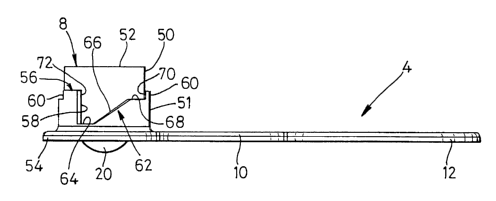
The body portion 4 is shown in greater detail in Figures 3 to 6. The body 8
has a generally
cylindrical wall 50, an upper face 52 and a base portion 54. The wall 50 has
an enlarged
lower portion 51 having shapings 56 formed in an upper part thereof as shown
in Figure 3.
The shapings 56 are diametrically symmetrical and comprise two identical sets
of shapings
56 provided about the circumference of the body 8. Each set of shapings 56
comprises an
abutment edge 58 extending parallel to the axis 16, a stop 60 and a ramming
surface 62
located between the abutment edge 58 and the stop 60. The ramming surface 62
has a first
flat portion 64 which extends circumferentially from the abutment edge 58 to
an inclined
portion 66. The inclined portion 66 extends upwardly from the first flat
portion 64 at an
angle of substantially 40° to the base portion 54. The inclined portion
66 extends to a
second flat portion 68. The second flat portion 68 extends circumferentially
around the
wall 50 from the inclined portion 66 to adjoin a stop face 70 of the stop 60.
The stop 60 is
generally rectangular in side view and extends upwardly from the second flat
portion 68.
An edge 72 of the stop 60 remote from the stop face 70 is in register with the
abutment
edge 58.
The base portion 54 is generally circular in plan view as shown in Figures 5
and 6. Lugs 80
are provided in the base portion 54 for locating and securing an axle 100. The
axle 100 can
be fixedly held between the lugs 80 by adhesive, welding, snap-fit or any
other convenient
means. The axle 100 is located so as to lie perpendicular to the axis 16. The
rolling
support member 20 is freely rotatably mounted on the axle 100 between the lugs
80. The
handle portion 10 has parallel sides and is integrally moulded with the
gripping portion 12.
The gripping portion 12 is circular in plan view and forms a loop at the end
14 of the
handle portion 10. The handle portion 10 extends radially outwardly from -the
base portion
54 in a direction perpendicular to the axle 100. The axle 100, the handle
portion 10 and the
axis 16 are mutually orthogonal.
CA 02401257 2002-08-23
WO 01/71086 PCT/GBO1/00714
6
The upper face 52 of the body 8 is generally planar and has an aperture 150
located
centrally about the axis 16. The aperture 150 has a chamfered upper edge 152
for reasons
which will be described below.
The housing 6 of the mechanism 2 is shown in Figures 7 to 9. The housing 6
comprises a
socket portion 200 and a flange portion 202. The socket portion 200 has a
generally
cylindrical wall 204 having an outer surface 206 and an inner surface 208. The
outer
surface 206 has shapings moulded therein which have no specific function. The
inner
surface 208 has a caroming surface 210 formed therein. The caroming surface
210 is
complementary to the caroming surface 62 of the body 8 and comprises a first
flat portion
212 which extends circumferentially from an abutment edge 214 to an inclined
portion 216.
The inclined portion 216 extends upwardly from the first flat portion 212 to a
second flat
portion 218. The second flat portion 218 extends circumferentially from the
inclined
portion 216. The formation is repeated in a diametrically opposing manner.
Additionally
the caroming surface 210 has a shoulder 224 located part-way along the
inclined portion
216. The flange portion 202 has diametrically opposed holes 203 the purpose of
which will
be described below.
The socket portion 200 has an upper end face 226. A hollow cylindrical peg 228
depends
from the upper end face 226 about the axis 16. An outwardly projecting lip 230
is provided
at a lower end 232 of the peg 228.
When the mechanism 2 is assembled in a first position, the housing 6 receives
the body 8 of
the body portion 4. The peg 228 projects through the aperture 150 and, the lip
230
cooperates with the lower edge of the aperture 150 in a snap-fitting manner.
The caroming
surface 62 of the body 8 lies against the caroming surface 210 of the socket
portion 200
such that the abutment edge 58 lies against the abutment edge 214, the first
flat portion 64
lies against the first flat portion 212, the inclined portion 66 lies against
the inclined portion
216, and the second flat portion 68 lies against the second flat portion 218.
CA 02401257 2002-08-23
WO 01/71086 PCT/GBO1/00714
7
In use, the housing 6 is rigidly fixed to an appliance. Movement of the
gripping portion 12
in the direction of arrow A from the first position (as shown in Figure 2)
causes relative
rotation between the housing 6 and the body 8. The caroming surface 62 moves
across the
caroming surface 210 such that the inclined portion 66 causes the housing 6 to
move axially
with respect to the body 8. During this movement, the body portion 4 moves
through an
angle of between 50° and 75°. Subsequently thereto, the first
flat portion 212 moves across
the second flat portion 68 to allow further rotation of the body portion 4
about the axis 16
through an angle of substantially 45° to 70° with no further
axial movement. Further
movement in the direction of arrow A is prevented by the abutment of the stop
face 70
against the shoulder 224 such that the stop 60 lodges in the shoulder 224. In
this
configuration, the mechanism 2 is in a second position. The mechanism 2 is
prevented
from rotating in the direction of arrow B from the first position by the
abutment of the
abutment edge 214 against the abutment edge 58.
Figures 10a to l 1b illustrate the mechanism 2 located in an appliance 400.
The appliance
400 as shown has a front surface 402, a base 404, feet 406 and castors 408.
The feet 406
are mounted at opposing corners 410 adjacent the front surface 402. The feet
406 are
moulded from rubber material. The feet 406 support the appliance 400 on the
floor 414.
The castors 408 are freely rotatably mounted at the rear 416 of the appliance
400 at
opposing corners 418.
In the first position as shown in Figures 10a and 10b, the mechanism 2 is
inoperative. The
appliance 400 stands stably on the floor 414 being supported both by the feet
406 and the
castors 408. The housing 6 is fixedly mounted in the base 404 of the appliance
400
generally centrally of the front surface 402 thereof. The flange portion 202
is fixedly
mounted on the base portion 404 by screws fitted through the holes 203
thereof. The
handle portion 10 is parallel to the front surface 402. In this first
position, the mechanism 2
CA 02401257 2002-08-23
WO 01/71086 PCT/GBO1/00714
8
is generally hidden from view, although a small part of the gripping portion
12 extends
beyond the front surface 402 to indicate to the consumer where the mechanism 2
is located.
To bring the mechanism 2 into the second position as shown in Figures lla and
11b, the
consumer pulls the gripping portion 12 outwardly from the front surface 402
thereby
rotating the body portion 4 with respect to the housing 6 until the handle
portion 10 lies
generally perpendicular to the front surface 402. The consumer's action causes
the rolling
support member 20 to be pressed onto the floor 414 thereby lifting the feet
406 clear of the
floor 414. In this position, the appliance 400 is tripodally supported by the
rolling support
member 20 and the castors 408. The consumer can then manoeuvre and steer the
appliance
400 from this lifted position.
To steer the appliance 400, the consumer is able to alter the angle at which
the handle
portion 10 extends away from the front surface 402 by substantially 25°
to either side of the
perpendicular direction. Because, in this range of angles, the first flat
portion 212 moves
across the second flat portion 68, the direction of the handle portion 10 can
be altered
without lowering the appliance 400 onto its feet 406. The axle 100 on which
the rolling
support member 20 is mounted is determined by the direction in which the
handle portion
extends to provide a steering mechanism for the appliance 400. When a pulling
force is
applied to the gripping portion 12, the rear castors 408 follow the direction
of the steering
mechanism. This configuration enables the consumer to manoeuvre the appliance
400 in
directions other than, but including, forwards and backwards, also having the
capability to
reposition the appliance 400 should the need arise. .
The mechanism 2 is moulded from resilient plastics but could also be made from
any other
suitable material. The mechanism 2 can be used in a range of appliances
particularly
domestic appliances, for example washing machines.
CA 02401257 2002-08-23
WO 01/71086 PCT/GBO1/00714
9
The invention is not limited to the precise details of the embodiment
described above. The
handle portion 10 could be a different shape; for example, it could be curved
or arcuate
while extending generally radially from the axis 16. The gripping portion 12
could form a
natural extension of the handle portion 10 or, alternatively, it could be any
suitable shape
for gripping. The body 8 could have more than two sets of shapings 56; for
example, three
equispaced shapings 56 may be incorporated. The snap-fit mechanism holding the
socket
portion 200 and the body portion 4 together could incorporate means other than
the peg 228
and aperture 150 assembly as described above. The flange portion 202 on the
housing 6
can be made to suit the appliance 400 and can be fitted to the appliance 400
for example by
any suitable means. The socket portion 200 could be non-circular in shape so
as to slot into
the appliance 400 in a push-fit manner. Other variations may include more than
one rolling
support member 20 mounted on the axle 100.