Note: Descriptions are shown in the official language in which they were submitted.
CA 02401260 2002-08-23
WO 01/71248 PCT/USO1/04605
-1-
LIGHT GUIDES SUITABLE'FOR ILLUMINATED DISPLAYS
Field of the Invention
The present invention relates to light guides suitable for use in illuminated
displays.
Backimound of the Invention
It is already known to use light guides to illuminate panels for general
lighting
purposes and for display applications (e.g. for illuminating signs and
advertisements,
and also for illuminating liquid crystal displays). In one form, often
referred to as a
light box, the light guide comprises a hollow box-shaped structure defining an
optical
cavity, and in another form it comprises a solid light-guiding plate. In both
forms, a
major surface of the guide can be illuminated by light directed into the guide
in a
direction generally parallel to that major surface, for example from at least
one
elongated light source located adjacent an edge of the light guide.
Light guides in the form of hollow light boxes are described, for example, in
EP-A-0 490 279; 0 377 309; and 0 293 182; and in GB-A-2 310 525. In each of
those
light boxes, a prismatic optical film is employed with a view to achieving a
more even
distribution of light over the surface that is being illuminated. In addition,
an
Application Bulletin entitled "Thin Light Box" and issued in March 1990 by
Minnesota
Mining and Manufacturing Company of St. Paul, Minnesota, USA describes the
design
and construction of light boxes, using ScotchTM Optical Lighting Film in
combination
with a shaped sheet of V-5115 ScotchT"' Light Extractor Film, for use in
illuminating
graphic displays.
In the case of light guides in the form of solid light-guiding plates, it is
well
known to form light-extraction elements of some type on the rear major surface
of the
plate with a view to achieving a more even distribution of light over the
front surface
(i.e. the surface that is being illuminated). In some cases, printed light-
extraction
elements are used and are applied directly to the rear surface of the light-
guiding plate.
Arrangements of that type are described, for example, in US-A-5 736 686; 5 649
754; 5
600 462;5 377 084; 5 363 294; 5 289 351; 5 262 928; 5 667 289; and 3 241 256.
CA 02401260 2002-08-23
WO 01/71248 PCT/US01/04605
-2-
US-A-5 618 096 describes light-emitting panels of various types and mentions
the possibility of providing light-extracting deformities on one or both sides
of a panel
to control the amount of light emitted from any area of the panel. It is also
mentioned
that the deformities may be printed on a sheet or film which is used to apply
the
deformities to the panel member. WO 92/05535 describes an illuminated display
system comprising a transparent panel with a dot matrix applied to both sides
and an
opaque backing sheet attached to the rear side. An image to be illuminated is
printed
on a further sheet positioned on the front side of the panel.
As recognised in previous disclosures, the problems to be addressed in
constructing a light guide for illumination purposes include achieving a
uniform level
of brightness across the panel that is being illuminated, and minimising the
amount of
power required to produce a level of illumination that is adequate having
regard to the
circumstances. As regards the first of those problems, it is often the case
that the panel
is more brightly illuminated in the area closest to the light source, which
detracts from
the overall visual appearance and effectiveness of the illumination. As
regards the
second of those problems, it is clearly highly desirable, from an
environmental and a
cost point of view, that the amount of power used for illumination purposes
should be
kept as low as possible. Moreover, when the power is derived from a battery
(as may
be the case when LCD and computer displays are being illuminated) it is also
generally
desirable that the amount of power utilized should be minimized so that the
battery can
be kept as small and light as possible.
In addition to those considerations, it would be advantageous to be able to
produce, comparatively easily and in a cost-effective manner, light guides of
widely-
differing dimensions that would be suitable for use in a variety of situations
but would,
nevertheless, function with a high level of efficiency.
Summary of the Invention
The present invention provides a light guide comprising a housing defining a
light-guiding optical cavity having first and second opposed major faces, and
at least
one light source arranged to direct light into the cavity from one end, to be
guided
between the major faces; wherein the first major face comprises a window
through
CA 02401260 2002-08-23
WO 01/71248 PCT/USOl/04605
-3-
which light can be emitted from the optical cavity, and the second major face
comprises a sheet material having a specularly-reflecting surface that faces
into the
cavity and has diffusely-reflecting light-extraction elements applied thereto
in a
predetermined configuration for causing light to be emitted from the optical
cavity
through the said window.
The term "light extraction element" in this context indicates a structure
capable
of reflecting light at such an angle that it will be emitted from the optical
cavity through
the said window. In a preferred form, the light extraction elements are
printed elements
formed in a diffusely-reflecting material. As used herein, the term "printed"
includes
the case in which the diffusely-reflecting material is deposited by a
conventional
printing process involving temporary contact between a printing surface (in
which the
shape of at least one light extraction element is pre-defined) and the surface
on which
the light extraction elements are to be formed. It also includes the case in
which the
diffusely-reflecting material is deposited by being projected at predetermined
locations
onto the surface on which the light extraction elements are to be formed.
Light guides in accordance with the invention can be produced in different
sizes
using comparatively lower cost materials and in a manner that is appropriate
to high
volume production, and can enable the effective, uniform, and efficient
illumination of
display panels using available light sources.
Brief Description of the Drawings
By way of example, embodiments of the invention will be described with
reference to the accompanying drawings, in which:
Fig. 1 is a perspective view of a light guide in accordance with the
invention;
Fig. 2 is a diagrammatic perspective view of a light guide, similar to that
shown in Fig.
1, the light guide being shown partly exploded;
Fig. 3 is a diagrammatic cross-sectional view of the light guide in exploded
form on the
line III-III of Fig. 2;
Fig. 4 illustrates the rear face of a light guide of the type shown in Figs. I
to 3;
Fig. 5 is a graph illustrating a characteristic of the rear face of a light
guide of the type
shown in Figs. 1 to 3;
CA 02401260 2002-08-23
WO 01/71248 PCT/USO1/04605
-4-
Figs. 6 and 7 are views, similar to Figs. 3 and 4, of another light guide and
of the rear
face of that light guide;
Fig. 8 is a graph, similar to Fig. 5, for the rear face shown in Fig. 7; and
Fig. 9 illustrates a modification of the light guide of Figs. 2 and 3.
Detailed Description
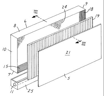
The light guide 1 shown in Fig. 1 comprises a box-like housing 3 defining an
optical cavity. The housing 3 has opposed major faces 5, 6, and opposed narrow
sides
7, 8 and 9, 10. An elongate light source 11 is arranged adjacent one of the
narrow sides
7 to direct light into the optical cavity in a direction generally parallel to
the planes of
the major faces 5, 6. One of the major faces (the face 5) forms a window
through
which light can be emitted from within the optical cavity and used for
illumination
purposes.
The optical cavity 13 inside the housing 3 is visible in the diagrammatic
illustration of Fig. 3. The narrow side 7 of the housing adjacent the light
source 11
comprises an optical sheet material 15 forming a window through which light
from the
source 11 can enter the light guide 1. Preferably, the sheet material 15 has a
structured
surface on the side remote from the light source, to redirect the light from
the source 11
and ensure that the light that passes through this window enters the optical
cavity 13
preferentially in a direction generally parallel to the planes of the faces 5,
6. The optical
sheet material 15 may, for example, have a structured surface comprising a
series of
ridges and grooves formed by a plurality of parallel triangular prisms. A
similar use of
sheet material of that type is described in EP-A-0 293 182. In the light guide
1, the
material 15 is preferably oriented so that the prisms extend parallel to the
elongate light
source. Suitable sheet material is available, under the trade designation
"ScotchTM
Optical Lighting Film" from Minnesota Mining and Manufacturing Company of St.
Paul, Minnesota, USA.
The narrow side 8 of the light guide 1 opposite the window 15 has a reflecting
surface 17 on the side facing into the optical cavity 13. This reflecting
surface, which
is preferably a highly-efficient specularly-reflecting surface, can be
provided by any
suitable material but is preferably provided by a multi-layer optical film of
the type
CA 02401260 2002-08-23
WO 01/71248 PCT/USO1/04605
-5-
described in US-A-5 882 774 and W097/01774. A suitable alternative material is
a
silver reflective film, for example the film available under the trade
designation
"Silverlux", from Minnesota Mining and Manufacturing Company of St. Paul,
Minnesota, USA.
The other two opposed narrow sides 9, 10 of the light guide also have
reflecting
surfaces 18 facing into the cavity. In this case, the reflecting surfaces are
preferably
provided by a film material available, under the trade designation "Light
Enhancement
Film" from Minnesota Mining and Manufacturing Company of St. Paul, Minnesota,
USA. However, any other suitable reflecting material can be used: generally,
it has
been found that a diffusely-reflecting material is preferable when the
length/width ratio
of these narrow sides is less than 10 and that a specularly-reflecting
material is
preferable when this ratio is greater than 10. It will be appreciated that
this ratio
corresponds to the length/thickness ratio of the light guide 1(otherwise known
as its
"aspect ratio").
The front face, or window, 5 of the light guide comprises an optical sheet
material 19 that, preferentially, guides the light from the source 11 along
the optical
cavity 13 between the faces 5, 6 and permits light to leave the optical cavity
only when
it is incident on the material 19 at certain angles. More specifically, the
sheet material
19 has a smooth surface facing into the optical cavity and, on the side facing
away from
the optical cavity, a structured surface comprising a series of ridges and
grooves formed
by a plurality of parallel triangular prisms whereby light incident on the
material 19
while travelling along the optical cavity 13 will be totally internally
reflected provided
it is incident on the material 19 within a predetermined angular range. As
such, the
material 19 may be the same as the material 15 and, in this case, the material
is oriented
so that the prisms extend in a direction at right angles to the direction of
extent of the
light source 11 as indicated in Fig. 2. A similar use of material of that type
is described
in EP-A-0 293 182. To protect the prismatic structures on the sheet material
19, a
further panel 21 may be positioned adjacent the material 19 on the outside of
the light
guide housing. This further panel is not essential but, when provided, it may
comprise a
sheet of opalescent light-diffusing material to enhance even further the
uniformity of
the light that passes through the sheet material 19.
CA 02401260 2002-08-23
WO 01/71248 PCT/USO1/04605
-6-
The rear face 6 of the light guide 1 comprises a sheet material 23 which
provides a highly-efficient specularly-reflecting surface 24 facing into the
optical cavity
13. The reflecting surface 24 should be such that its reflectivity is not
reduced
substantially for light that is incident in directions other than normal to
the surface, and
is at least 90% (preferably at least 98%). Preferably, the sheet material 23
is a multi-
layer optical film of the type described in US-A-5 882 774 and WO 97/01774. A
suitable alternative material, particularly for light guides that have a
comparatively low
aspect ratio (less than about 10), is available, under the trade designation
"Silverlux",
from Minnesota Mining and Manufacturing Company of St. Paul, Minnesota, USA.
As described in greater detail below, the specularly-reflecting surface 24
carries
diffusely-reflecting light-extraction elements in a predetermined
configuration to cause
light to be emitted from the optical cavity 13, through the window 5, in a
controlled
manner. In this case, the light-extraction elements comprise an array of dots
27 formed
in a diffusely-reflecting material on the surface 24 as shown in Fig. 4.
In Figs. 2 and 3, the light source 11 is shown as being located in a three-
sided
housing 25, the open side of which is positioned adjacent the sheet material
15 forming
the entry window of the light guide 1. The housing 25 is constructed with a
view to
ensuring that the light source 11 directs as much light as possible into the
optical cavity
13 and, to that end, the internal surfaces of the housing may be covered with
a suitable
highly-efficient, diffusely reflecting material, for example a reflective
paint or sheet
material. Alternatively, the light source 11 could be provided with a
parabolic reflector
to direct the light from the source towards the optical cavity 13, or it could
be replaced
by a suitable apertured light source. The use of the sheet material 15 in the
narrow side
7 of the light guide housing adjacent the light source 11, although preferred,
is not
essential.
The light guide 1 as described above functions as follows. Light from the
source 11 (possibly following reflection or redirection at the walls of the
housing 25)
enters the optical cavity 13 through the window material 15 and travels
preferentially in
a direction parallel to the major surfaces 5, 6 of the light guide towards the
surface 17
where it will be reflected and returned. However, any light that is incident
on the
extraction elements on the rear surface 24 (i.e. the dots 27) will be
diffusely reflected
CA 02401260 2002-08-23
WO 01/71248 PCT/USO1/04605
-7-
and some of that light will, as a consequence, impinge on the front face 5 of
the light
guide at such an angle that it can pass through the optical sheet material 19
and emerge
from the light guide.
The use of light-extraction elements of various forms to cause light to be
emitted from light guides is already well known. In the light guide of Figs. 1
to 3, the
light-extraction elements 27 (as already mentioned) comprise an array of dots
formed in
a diffusely-reflecting material on the specularly-reflecting surface 24. The
circular
form of the light extraction elements is not essential, however, and they may
be of any
shape (for example squares, triangles, lines, etc) that can readily be formed
by a
printing process, and may even comprise a mixture of shapes and/or sizes.
Light-
extraction elements in the form of continuous lines on the reflecting surface
24 are also
possible. Preferably, the light-extraction elements 27 are formed by being
printed
directly onto the reflecting surface 24 but they could, as an alternative, be
printed on a
transparent sheet which is then adhered to the surface 24. Moreover, although
the use of
printed light extraction elements is preferred, other forms could be employed
as
described below.
The printed light extraction elements 27 on the reflecting surface 24 of the
light
guide 1 are positioned to provide a required illumination pattern over the
front face 5 of
the light guide. In many cases, a uniform illumination of the face 5 is
required and that
can be achieved if the percentage area of the surface 24 that is covered by
the diffusely-
reflecting elements 27 varies (most typically, increases) with the distance
from the light
source 11 (measured in the direction at right angles to the direction of
extent of the light
source). That is illustrated diagrammatically in Fig. 4, in which it will be
seen that the
proportion of the surface 24 of the sheet material 23 that is covered by the
light
extraction elements 27 is zero in the region immediately adjacent the light
source 11
and then increases as the distance from the light source increases. In Fig. 4,
the surface
coverage of the light extraction elements 27 is shown reaching a maximum value
at a
short distance from the other end of the sheet 23 and then decreasing slightly
in the
region furthest from the light source 11. This decrease is provided to
accommodate the
effects of the reflective surfacel7 at the far end of the optical cavity 13;
the need for it
(and its extent), will be determined in each case by the particular
configuration of the
CA 02401260 2002-08-23
WO 01/71248 PCT/USO1/04605
-8-
light guide. It should be understood that Fig. 4 is purely diagrammatic and
that the
variation in the surface-coverage of the light-extraction elements 27 would
typically be
continuous rather than discontinuous as shown in this drawing. A more typical
variation in the surface-coverage of the light-extraction elements 27 is
illustrated in Fig.
5 which shows that the surface coverage is zero over the first 10% of the
length of the
optical cavity 13 measured from the light source 11 and then increases
linearly,
reaching 100% (i.e. total coverage) at a distance of about 90% of the length
of the
optical cavity measured from the light source. The surface coverage then
decreases
slightly at the end of the optical cavity 13 remote from the light source 11.
Figs. 6 and 7 illustrate a light guide 31 that is generally similar to the
guide
illustrated in Figs. 2 to 4 but utilises an additional light source 11'
positioned opposite
to the light source 11 (i.e. adjacent the narrow side 8 of the housing 3). To
enable light
from the source 11' to enter the optical cavity 13, the side 8 of the housing
3 comprises
an optical sheet material 15' forming a window, rather than the reflecting
material 17 of
Fig. 3. In addition, the rear surface 24 of the light guide is provided with a
suitably-
modified configuration of light-extraction dots 27', described in greater
detail below.
The light source 11' is located in a three-sided housing 25' similar to that
of the
light source 11 but, like the light source 11, it could alternatively be
provided with a
parabolic reflector to direct light from the source into the optical cavity,
or be replaced
by a suitable apertured light source. The material 15' forming the window from
the
housing 25' into the optical cavity 13 is preferably the same as the optical
sheet material
15.
The light guide 31 functions in a similar manner to the guide 1 described
above
except that, in this case, light from both sources 11, 11' (possibly following
reflection
or redirection at the walls of the associated housing 25, 25') enters the
optical cavity 13
through the associated window material 15, 15' and travels preferentially in a
direction
parallel to the major surfaces 5,6 of the light guide towards the light
housing at the
other end of the optical cavity where some of the light will be reflected and
returned.
Any light that is incident on the extraction elements on the rear surface 24
(i.e. the dots
27) will be diffusely reflected and some of that light will, as a consequence,
impinge
CA 02401260 2002-08-23
WO 01/71248 PCT/USO1/04605
-9-
on the front face 5 of the light guide at such an angle that it can pass
through the
optical sheet material 19 and emerge from the light guide.
As with the light guide 1 of Figs. 2 to 4, the printed light extraction dots
27' on
the reflecting surface 24 of the light guide 31 are positioned to provide a
required
illumination pattern over the front face 5 of the light guide. In many cases,
a uniform
illumination of the face 5 is required and that can be achieved if the
percentage area of
the surface 24 that is covered by the diffusely-reflecting dots 27' varies
(most typically,
increases) with the distance from each of the light sources 11, 11' (measured
in the
direction at right angles to the direction of extent of the light sources) up
to a maximum
in the central region equidistant from both light sources. That is illustrated
diagrammatically in Fig. 7, in which it will be seen that the proportion of
the surface 24
of the sheet material 23 that is covered by the light extraction elements 27'
is zero in the
regions immediately adjacent the light sources 11, 11' and then increases in
each case
as the distance from the respective light source increases, reaching a maximum
value in
the central region 33 of the surface. It should be understood that Fig. 7 is
purely
diagrammatic and that the variation in the surface-coverage of the light-
extraction dots
27' would typically be continuous rather than discontinuous as shown in this
drawing.
A more typical variation in the surface-coverage of the light-extraction
elements 27' is
illustrated in Fig. 8 which shows that the surface coverage is zero over the
first 10% of
the length of the optical cavity 13 measured from each of the light sources
11, 11' and
then increases linearly, reaching 100% (i.e. total coverage) in a central
region at a
distance approaching 40% of the length of the optical cavity measured from
each light
source.
Figs. 4 and 7 both indicate that the surface-coverage provided by the light-
extraction elements 27, 27' is varied by changing the number of dots per unit
area of the
surface 24 while maintaining a uniform dot size. As an alternative, the size
of the
extraction elements can be changed while maintaining a constant number of
extraction
elements per unit area of the surface 24 and, as a further alternative, both
the size of the
extraction elements and the number per unit area can be varied.
CA 02401260 2002-08-23
WO 01/71248 PCT/US01/04605
-10-
In some cases, it may also be appropriate to vary the surface-coverage of the
light extraction elements 27, 27' transversely of the optical cavity (i.e. in
a direction
parallel to the direction of extent of the light source(s) 11, 11').
The extraction elements 27, 27' of Figs. 4 and 7 can be printed using any
suitable printing medium that will function as a difiuse reflector and is
compatible with
the reflecting surface 24 and with the printing process employed. One suitable
medium
is a highly-efficient diffusely-reflecting matt white ink. Any suitable
printing process
can be used to deposit the printing medium on the surface of the sheet
material,
including screen printing, gravure printing, offset printing. Ink jet printing
may also be
employed. In a preferred process, the printing medium is deposited using a
conventional silk screen printing process because that is a versatile,
comparatively low-
cost process which is suitable for long production runs but nevertheless
enables good
control to be maintained over the size of the extraction elements 27, 27'. The
extent to
which the reflecting surface 24 should be covered by the printing medium can
be
determined empirically for a particular light guide by providing an arbitrary,
linearly-
varying, pattern of extraction elements 27, 27' on the surface 24 and
comparing the
resulting illumination of the front face 5 of the light guide with that
achieved in the
absence of any extraction elements. The pattern is then adjusted, on the basis
of that
comparison to yield the illumination required.
Although it is generally required to achieve a constant level of illumination
across the front face 5 of the light guide 1, 31 there may be occasions when
it is
desirable to provide a level of illumination that varies across the face 5 in
a pre-
determined manner. For example, the level of illumination across the front
face 5 could
be matched to the image that is being illuminated so that the brighter parts
of the image
receive more light and the darker parts of the image receive less. That could
be
achieved, for example, by first providing, on the reflecting surface 24, the
pattern of
extraction elements 27, 27' required to provide uniform illumination of the
front face 5
and subsequently superimposing, on that pattern, further extraction elements
arranged
in an image-dependent configuration. The further extraction elements could,
for
example, be printed directly over the elements 27, 27' or they could be
printed on a
separate transparent sheet which is then adhered to the already-printed
surface 24. As
CA 02401260 2002-08-23
WO 01/71248 PCT/USO1/04605
-11-
an alternative, the further extraction elements could be provided on the
smooth surface
of the optical sheet material 19 in the front face 5 of the light guide, in
which case they
should be formed of a translucent material, capable of both reflecting and
transmitting
incident light from within the optical cavityl3. As a further alternative, the
extraction
elements 27, 27' could be omitted from the reflecting surface 24 (at least in
certain
areas) with only the further, image-related, extraction elements being
provided.
An arrangement of the type referred to in the previous paragraph is
illustrated
diagrammatically in Fig. 9, for a light guide intended to be illuminated by a
single light
source 11 as in Figs. 2 and 3. The reflecting surface 24 carrying the pattern
of
extraction elements 27 required to provide uniform illumination of the front
face of the
light guide is shown, in combination with a sheet 35 carrying the graphic
image to be
illuminated. Superimposed on the reflecting surface 24 is a transparent sheet
37
carrying further extraction elements 39 arranged in an image-related
configuration
whereby the brighter parts of the image receive more light and the darker
parts of the
image receive less. Typically, the graphic image on the sheet 35 is a
digitally-printed
image, in which case the image data file that is used to print the image can
also be used
to print the extraction elements 39 on the sheet 37 taking account, if
required, of
factors such as the nature of the inks used in the graphic image and the
spectral
sensitivity of the human eye.
Although Fig. 9 shows the further extraction elements 39 located on the
separate sheet 37, it will be understood that they could alternatively be
located on the
reflecting surface 24. In that case, when using a digital printing process,
all of the
required light extraction elements (i.e. elements 27 as well as elements 39)
can readily
be deposited on the surface 24 together.
The use of a sheet material 23 for the rear face of the optical cavity 13 of
the
light guides 1, 31 is advantageous because such a material is easy to handle,
not only
during the actual printing process (when the fact that the sheet material has
flat,
unstructured, surfaces is a particular advantage) but also during any
subsequent drying
and storage stages prior to assembly of the light guide. When in use in the
light guide,
the reflective sheet material 23 prevents light from leaving the optical
cavity 13 through
the rear face 6 and thus enhances the illumination of the front face 5. In
addition, any
CA 02401260 2002-08-23
WO 01/71248 PCT/US01/04605
-12-
scratches on the surface of the reflective sheet material (which might arise,
for
example, during handling or assembly of the light guide) will not adversely
affect the
illumination of the front face 5. Moreover, because the extraction elements 27
are
printed on a planar reflecting surface 24 there is also no risk of more
interference
patterns arising even when the extraction elements are disposed in a regular
array.
The printing medium used to form the extraction elements 27, 27' is selected
for
compatibility with the sheet material to which it is applied, as well as for
its durability
and diffusely-reflecting characteristics. Highly-opaque white inks are
preferred and it
has been found that the best printing quality is obtained using UV-cured inks
in a
screen printing process. Screen printing offers the further advantage that the
ink layer
deposited on the sheet material 23 is thick and, consequently, comparatively
robust and
also less likely to fade and discolour. Moreover, unlike some printing
processes, the
screen printing process does not entail the application of high pressures to
the material
23 and is less likely to damage the latter. It can also be used to apply the
printing
medium to a wide range of different sheet materials in a wide range of sizes.
It should
be understood, however, that other media could be employed to form the light
extraction elements 27, 27', as could other processes including, for example,
laser
printing, ink jet printing, thermal transfer printing and thermal ink jet
printing.
In some cases, the extraction elements 27, 27' may be formed by other methods,
including, for example, surface roughening of the sheet material or deposition
of
diffusely-reflecting material (which may include particles) in a required
configuration
using coating or spraying processes.
A hollow light guide as described above with reference to Figs. 1 to 3 or 6
can
be fabricated in such a way that it is comparatively lightweight. That is a
particular
advantage when the light guide is large in size (for illuminating large signs,
for
example), and especially when it is required to be installed in a less
accessible location.
It also makes the use of thicker light guides (which offer the possibility of
admitting
more light into the optical cavity 13) more practical. It is also
comparatively simple to
fabricate light guides of this type in many different sizes and, in
particular, with widely
differing aspect ratios (i.e. different length/thickness ratios). For example,
light guides
of this type can be produced with aspect ratios as small as 5 and as large as
100 and, in
CA 02401260 2002-08-23
WO 01/71248 PCT/USOl/04605
-13-
both cases, will function efficiently. Light guides with small aspect ratios
offer the
advantage that the light admitted to the optical cavity 13 undergoes fewer
reflections
before it is emitted through the window 5. Consequently, the level of accuracy
required
in the configuration of the light extraction elements 27, 27' is lower.
Of particular interest in the field of illuminated signs is the fact that
light guides
of the type shown in Figs 1 to 3 and 6 can be fabricated with widths as small
as 10cm
and even, depending on the size of the sign, as small as 3cm. Light guides of
this type,
having low aspect ratios (typically less than 10) and using conventional
fluorescent
tubes as light sources, have been found to have performance efficiencies that
compare
favourably (and, in some cases, very favourably) with those that can be
achieved using
solid light guides. In the alternative case in which the light guides have
larger aspect
ratios, they are found to be better able than solid light guides to
accommodate some
degree of misalignment of the light source.
The light sources employed with the light guides 1, 31 are not required to
have
an elongate form as illustrated. Other light sources could be employed
including, for
example, light emitting diodes (LEDs). Depending on the form of the light
source,
more than one source may be used to direct light into the optical cavity 13
through the
adjacent side of the housing 3. In that case, the surface-coverage of the
light extraction
elements 27, 27' may also vary transversely of the optical cavity (i.e.
between the sides
9, 10).
The light guides illustrated in Figs. 1 to 3 and 6 have been described above
as
being used to illuminate a graphic display but they could be used for other
purposes
including, for example, to illuminate liquid crystal displays.
An example of an illuminated sign incorporating a light guide of the type
illustrated in Figs. 1 to 3 will now be described.
The housing 3 of the light guide 1, excluding the front major face 5, may be a
one-piece vacuum-formed construction of any suitable material, for example PVC
(polyvinylchloride). Alternatively, the housing may be formed from several
pieces of,
for example, an acrylic material, each providing one side of the housing,
which are
secured together in any suitable manner. The housing is approximately 60 x 60
x
4.5cm.
CA 02401260 2002-08-23
WO 01/71248 PCT/USO1/04605
-14-
The internal surface of the rear major face 6 of the housing is covered with a
sheet 23 of a specularly-reflective, multi-layer, optical film of the type
described in US-
A-5 882 774 and WO 97/01774, having a reflectivity in a direction normal to
the
surface of the film of at least 98%. The surface 24 of the film 23 facing into
the housing
3 carries a printed dot pattern providing a percentage surface coverage that
varies as
represented in Fig. 5. The dot pattern was screen printed on the surface 24 of
the film
23 using a white UV-cured ink of a type formulated for the printing of compact
discs (a
suitable ink being available from NOR-COTE of Eastleigh, Hampshire, England).
The
variation in percentage surface coverage of the surface 24 by the ink was
achieved by
varying the size of the dots while maintaining a constant number of dots per
unit area of
the surface (based on transverse lines of dots containing about 20 dots per
inch
(2.54cm)).
The internal surface of one narrow side 7 of the housing 3 is covered with a
sheet 15 of the above-mentioned "ScotchTM Optical Lighting Film", arranged
with the
prisms facing into the housing and extending parallel to the long edges of
this side of
the housing. The internal surface of the opposite narrow side 8 of the housing
3 is
covered with the same specularly-reflective film material as the internal
surface of the
rear major face 6 but without the printed dot pattern. The internal surfaces
of the
remaining two narrow sides 9, 10 of the housing 3 are covered with the above-
mentioned "Light Enhancement Film".
The housing 3 is closed with a sheet 19 of the above-mentioned "ScotchTM
Optical Lighting Film", forming the front major face 5. The film is arranged
so that the
prisms are on the outside of the housing and extend between the narrow sides 7
and 8.
The light guide module thus formed was put into a sign housing and provided
with a 60cm long, 14W fluorescent lighting tube located, within a high-
reflectance
housing 25, adjacent the narrow side 7 of the light guide housing 3 and
arranged to
direct light into the latter. It was found that the front major face 5 of the
housing 3 was
illuminated with a high degree of uniformity and to a level sufficient to
provide
effective illumination of a graphic image located in front of the face 5.