Note: Descriptions are shown in the official language in which they were submitted.
CA 02401296 2002-09-04
1
(a) TITLE: FLAME-RESISTANT SHEET WITH CANDLE WICK SUPPORT
(e) BACKGROUND OF THE INVENTION
1. Field Of The Invention
[0001 ] This invention relates generally to candles, and more specifically to
a
structure that reduces some fire hazards associated with burning a
freestanding candle.
2. Description Of'The Related Art
[0002] The information contained in U.S. Patent No. 5,842,850 to Pappas is
incorporated herein by reference.
[0003] A candle is one or more combustible wicks supported by a material that
constitutes a fuel, which is solid, semi-solid, or quasi-rigid at room
temperature, 68
degrees Fahrenheit to 80 degrees Fahrenheit (20 degrees Celsius to 26 degrees
Celsius); it
can also contain additives which are used for color, odor, stability, or to
modify the
burning characteristics; the combined function of which is to sustain a light-
producing
flame. A candle is freestanding if it is capable of standing upright on its
own without
requiring a support such as a container or a candle holder. The freestanding
candle burns
a fuel and has a flame that vaporizes the fuel as capillary action draws the
fuel up the
wick to the flame. As the fuel is burned, the flame generates heat that melts
the fuel into a
pool of liquid fuel, which accumulates around the wick in an interior region
of the candle.
[0004] A characteristic of the burning freestanding candle is the presence of
a
peripheral wall around the pool of liquid fuel. The peripheral wall is a
barrier that is
2 0 composed of fuel that remains integral as the candle burns. The wick is
positioned within
the freestanding candle, spaced from a candle outer surface a distance that
promotes the
formation of the peripheral wall, as the areas of fuel nearer to the heat of
the flame melt
into the pool. The pool of liquid fuel is desirably contained in the candle
interior from the
sides by the peripheral wall, thereby keeping the fuel from draining onto
surrounding
2 5 objects or surfaces.
[0005] The pool of liquid fuel is desirably contained in the candle interior
from
underneath by a candle floor. The candle floor is the inte~-al fuel underneath
the pool of
CA 02401296 2002-09-04
2
liquid fuel, having a thickness extending upwardly from a bottom surface of
the candle to
the bottom of the pool of liquid fuel, ending at an interface between the
integral fuel and
the liquid fuel at the pool bottom. The thickness of the candle floor
decreases as the
integral fuel is liquefied by the heat and consumed by the flame.
[0006] Freestanding candles often have a wick support to hold the wick, so
that
the wick does not fall over and ashes properly in the later stages of its
operative life.
During these stages, the flame and the pool of liquid fuel are usually located
deep in the
candle interior, and the wick support is often loosely sitting in the pool of
liquid fuel on a
thin candle floor. The wick support may tip and bring the flame into contact
with the
liquid fuel, which may be ignited. The liquid fuel can seep under the wick
support and
melt through any remaining fuel composing the thin candle floor. The liquid
fuel can
escape containment, flowing from the candle onto surrounding objects and
surfaces,
which may absorb the fuel. If the escaped fuel subsequently combusts, then the
heat can
ignite the fuel-soaked surroundings, and a candle fire results.
[0007] Other fire hazards that involve the formation of the pool of liquid
fuel and
the peripheral wall may arise as the freestanding candle burns. Factors that
can disrupt
the ability of the peripheral wall to contain the pool of liquid fuel include
air drafts and
placement of the candle in a non-vertical position, as well as a tipped wick
support. An
air draft can cause the flame to lean, which in turn causes the heat from the
flame to melt
2 0 one area of the peripheral wall more than another area. Similarly, non-
vertical placement
of the candle tilts the candle with respect to the longitudinal axis of the
wick. The tilt
brings one area of the peripheral wall closer to the flame, and the heat melts
the one area
of the peripheral wall more than another area. Likewise, a tipped wick support
can bring
the flame close to the peripheral wall. In all situations the heat from the
flame can melt a
2 5 passage through the peripheral wall, which compromises the structural
integrity necessary
to contain the pool of liquid fuel.
[0008] If the peripheral wall is not integral, then certain fire hazards
arise. As
when the thin candle floor melts, the pool of liquid fuel may drain from the
candle interior
through an opening in the melted peripheral wall, flowing onto and soaking
into
3 0 surrounding objects and the candle-supporting surface. Subsequent
combustion of the
fuel can ignite the objects or the surface. Additionally, the draining of
liquid fuel from
the candle interior results in a sudden decrease in the pool depth. The sudden
drop in the
CA 02401296 2002-09-04
3
pool depth exposes to the flame a portion of the wick that was formerly
underneath the
pool surface. The flame immediately spreads downwardly and rapidly consumes
this
unburned, liquid fuel-coated portion of the wick. The result is a dangerously
large flame
that can melt through the candle floor and large areas of the peripheral wall.
[0009] An additional fire hazard arises due to the sudden draining of liquid
fuel
from the candle interior. Some wicking can intentionally be manufactured to
arc and curl
through areas of the flame that oxidize the wick material to ash. Complete
disintegration
of the wick material results while burning slowly under normal burning
conditions, so no
wick material accumulates in the candle interior. However, after spreading
downwardly
due to the sudden draining of liquid fuel from the candle interior, the candle
soon returns
to normal burning conditions, and the flame becomes smaller at a new point on
the wick.
Often a top portion of the wick remains partially-combusted and outside of the
smaller
flame, because the top portion was unable to spend enough time in the
oxidizing part of
the flame prior to the pool draining. But, now the wick may completely ash at
the new
point on the wick by the smaller flame, so the top portion can lose support
and fall into
the pool. Subsequent combustion of the top portion may result in a dangerously
large
flame that can burn through the candle floor.
[0010] A similar fire hazard arises when combustible materials accumulate in
the
pool of liquid fuel. Such materials may include an unburned wick portion as
described
2 o above, carbon balls, and burned matches. These materials may be ignited by
the candle
flame, producing a secondary wick that can supplement the flaming wick and
make a
dangerously large flame. Heat from the flame can melt the candle floor and the
peripheral
wall, so surrounding objects and surfaces may become exposed to the flame.
Also, the
flaming secondary wick may float through melted areas of the peripheral wall,
off the side
2 5 of the candle and onto a flammable surface.
[0011 ] Carbon balls are incomplete products of combustion that have become
deposited on the end of the wick, and may include materials such as soot and
condensed
gas found in smoke. Carbon balls can detach from the wick and fall into the
pool of
liquid fuel, where they accumulate and become soaked with liquid fuel. The
liquid fuel
3 0 may combust, thereby igniting the carbon balls, which become secondary
wicks.
Likewise, a burned match in the pool of liquid fuel may become a secondary
wick.
CA 02401296 2002-09-04
4
[0012] Another fire hazard during the later stages of the operative life of
the
candle may arise when the pool of liquid fuel becomes shallow. The fuel in the
shallow
pool can become hot enough to vaporize and no longer needs the wick to burn.
This
phenomenon is called flash or flashover. Once the upper surface of the pool
descends
nearly to the bottom of the candle, the fuel can be elevated above its
flashpoint
temperature, typically about 425 degrees Fahrenheit with conventional, common
fuels.
During flashover, an ensuing candle fire may have a temperature elevated to at
least 1200
degrees Fahrenheit. The high temperature can ignite vaporized fuel, and a
container
holding the candle may break violently due to uneven stress on the container
caused by
the build-up of excessive heat. If the candle has no container, then in the
later stages of
burning the candle, the excessive heat can melt through the sides and bottom
of the
candle. Liquid fuel can flow onto and soak into surrounding objects and the
candle-
supporting surface. The fuel can ignite and combust the fuel-soaked
surroundings, and a
candle fire results.
[0013] The candle fire and flashover problems are addressed by causing the
flame
to be extinguished when the pool of liquid fuel becomes shallow. In a
freestanding candle
with a wick support, the flame extinguishes by making the wick support fuel-
impervious,
thereby preventing liquid fuel from flowing into contact with the lower end of
the wick
that is held within the wick support. When the surface of the pool of liquid
fuel descends
2 o below the top of the wick support, the flame becomes fuel-starved and is
quickly
extinguished. 1n this way, the accumulation of excessive heat is eliminated.
(f) BRIEF SUMMARY OF THE INVENTION
[0014] A sheet composed of a flame-resistant material is contacted to a fi~el-
2 5 impervious wick support, and joined to a freestanding candle in proximity
to a lower end
of a wick. The wick support has a seal that prevents the liquid fi~el from
reaching the
flame by capillary action through the lower end of the wick.
(g) BRIEF DESCRIPTION OF THE SEVERAL VIEWS OF THE DRAWINGS
3 0 [0015] Fig. 1 is a view in perspective of the preferred embodiment.
[0016] Fig. ? is a side view of the preferred embodiment.
[0017] Fig. 3 is a view in section of the preferred embodiment.
CA 02401296 2002-09-04
[0018] Fig. 4 is a view in section of the preferred embodiment.
[0019] Fig. 5 is a view in perspective of an alternative
embodiment.
[0020] Fig. 6 is a side view of an alternative embodiment.
[0021 ] Fig. 7 is a view in perspective of an alternative
embodiment.
5 [0022] Fig. 8 is a view in perspective of an alternative
embodiment.
[0023] Fig. 9 is a view in section of an alternative embodiment.
[0024] Fig. 10 is a view in perspective of an alternative
embodiment.
[0025] Fig. 11 is a view in section of an alternative embodiment.
[0026] Fig. 12 is a view in perspective of an alternative
embodiment.
[0027] Fig. 13 is a view in perspective of an alternative
embodiment.
[0028] Fig. 14 is a view in perspective of an alternative
embodiment.
[0029] Fig. 15 is a view in perspective of an alternative
embodiment.
[0030] Fig. 16 is a view in section of an alternative embodiment.
[0031] Fig. 1? is a view in perspective of an alternative
embodiment.
[0032] Fig. 18 is a view in perspective of an alternative
embodiment.
[0033] Fig. 19 is a view in perspective of an alternative
embodiment.
[0034] Fig. 20 is a view in perspective of an alternative
embodiment.
[0035] Fig. 21 is a view in perspective of an alternative
embodiment.
[0036] Fig. 22 is a view in perspective of an alternative
embodiment.
2 0 [0037] Fig. 23 is a side view of an alternative embodiment.
[0038] Fig. 24 is a view in perspective of an alternative
embodiment.
[0039] Fig. 25 is a view in perspective of an alternative
embodiment.
[0040] Fig. 26 is a view in perspective of an alternative
embodiment.
[0041 ] Fig. 27 is a view in perspective of an alternative
embodiment.
2 5 [0042] In describing the preferred embodiment of the invention,
which is
illustratedin the drawings, specific terminology will be resorted
to for the sake of clarity.
However, it is not intended that the invention be limited to
the specific term so selected,
and it is to be understood that each specific term includes all technical
equivalents that
operate in a similar manner to accomplish a similar purpose.
CA 02401296 2002-09-04
6
(h) DETAILED DESCRIPTION OF THE INVENTION
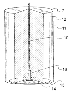
[0043] The utility of the invention is for a freestanding candle having a
width of at
least two inches, and structural elements of the preferred embodiment are
shown in Figs.
1-4. As depicted in Fig. 1, the freestanding candle is a fuel body 12 that has
a top surface
7, a bottom surface 13, and an outer peripheral surface 11. The fuel body 12
supports a
wick 10. A flame-resistant sheet 14 is joined to the fuel body 12, which has
been cut
away to show a wick support 16 contacting the sheet 14 and holding the wick
10.
[0044] The sheet 14 is flame-resistant, meaning that the sheet 14 will not
ignite
1 o when exposed to the flame on the wick 10 and the heat from the flame. The
sheet 14 is
composed of a material such as metal or plastic, and the thickness of the
sheet 14 may
vary. The sheet 14 in Fig. 1 is shown circular by a hyphenated line, but the
sheet 14 may
have a different form, such as a square shape. Preferably the sheet 14 is the
general shape
of the pool of liquid fuel that accumulates around the flame in the interior
of the fuel body
12. Also, the sheet 14 can serve as a label.
[0045) Fig. 2 shows the wick 10, the wick support 16, and the sheet 14. The
sheet
14 preferably extends outwardly at least one inch from the longitudinal axis
of the wick
10. The sheet 14 is at least two inches wide, because the effectiveness of the
sheet 14
diminishes below a two-inch width. Conversely, the effectiveness of the sheet
14
2 o increases above a two-inch width.
[0046] Fig. 3 is a view in vertical, axial section of the freestanding candle
undergoing normal burning, with the fuel body 12. The sheet 14 extends
substantially to
the outer peripheral surface 11 of the fuel body 12 and may extend all the way
to the outer
peripheral surface 11. Either way, the sheet 14 should sufficiently cover an
area of the
2 5 bottom surface 13 that corresponds to the pool of liquid fuel, which is
shaded in Fig. 3.
Figs. 1-3 show that the wick support 16 is contacted substantially in the
center of the
sheet 14.
[0047] Fig. 4 is a view in vertical, axial section of the preferred wick
support 16,
which has a barrel 25 mounted upright to a base 27. The wick support 16 is
composed of
3 0 a flame-resistant material like metal, ceramic, or plastic. A bore 21
extends upwardly
through the wick support 16, from a bore opening 22 in the base 27 through the
barrel 25.
The barrel 25 separates a lower end 9 of the wick 10 from the fuel body 12
(not shown).
CA 02401296 2002-09-04
7
A friction fit holds the lower end 9 of the wick 10 within the barrel 25. A
sealant 17
disposed in the bore 21 prevents the liquid fuel from flowing into contact
with the lower
end 9 of the wick 10. The sealant 17 may also serve to enhance support of the
wick 10 by
the wick support 16, when an excess amount of the sealant 17 disposed within
the bore 21
contacts and bonds the lower end 9 of the wick 10 to the inside wall of the
barrel 25.
[0048] The wick support 16 extends above the sheet 14 a length sufficient to
prevent a candle fire, which is at least one-half inch above the sheet 14. The
barrel 25 has
an increased length, which is an advantage over shorter barrels, because a
longer barrel 25
increases the distance the flame is suspended above the pool of liquid fuel.
If there is a
1 o barrier to the flow of liquid fuel into the base 27 of the wick support 16
and up the wick
10, then, even when the heat from the flame melts the fuel surrounding the
base 27, no
liquefied fuel can flow into the base 27 of the wick support 16 and up the
wick 10 to the
flame. As a result, the flame is extinguished when the surface of the pool of
fuel falls just
below the top of the barrel 25. The longer barrel 25 results in a thicker
candle floor once
the flame is extinguished and also increases the distance that the wick 10
must curl
downward to reach the pool of liquid fuel and cause the dangerously large
flame
described above.
[0049] The sealant 17 is a compound that resists melting and combusting when
exposed to the heat of the flaming wick 10, such as a thermosetting compound
or a
2 0 thermoplastic. The preferred sealant 17 is a flame-resistant hot-melt
thermoplastic glue
called MACROMELT TPX 16-157, manufactured by Henkel and distributed by Rudolph
Brothers and Company, Canal Winchester, Ohio. The sealant 17 also has adhesive
properties. The sealant 17 is disposed in the bore 21, at a position beneath
the lower end
9 of the wick 10. The sealant 17 forms a barrier to prevent liquid fuel from
flowing into
2 5 contact with the lower end 9 of the wick 10.
[0050] It is preferred that the sheet 14 is joined to the fuel body 12 at a
location in
proximity to the lower end 9 of the wick 10, which is held in the barrel 25.
In proximity
to means that the sheet 14 is lying next to, although it may not be in direct
contact with,
the lower end 9 of the wick 10. It is most preferred that the wick support 16
is sealingly
3 0 adhered to the sheet 14. Sealingly adhered means the wick support 16 is
bonded to the
sheet 14 in a way that prevents the liquid fuel from flowing under the base 27
of the wick
support 16, between the base 27 and the sheet 14. The sheet 14 has an adhesive
that
CA 02401296 2002-09-04
8
bonds the sheet 14 to the bottom surface 13 of the fuel body 12, and the
adhesive may
also serve to sealingly adhere the sheet 14 to the base 27. Alternatively or
in addition, an
excess amount of the sealant 17, protruding from the bore 21 through the bore
opening 22
and onto the sheet 14, may bond the base 27 to the sheet 14.
[0051] Forming the bond between the wick support 16 and the sheet 14 is
advantageous to reduce the risk of certain fire hazards. First, bonding the
wick support 16
to the sheet 14 prevents the wick support 16 from shifting laterally in the
pool of liquid
fuel, which would risk bringing the flaming wick 10 into contact with the
peripheral wall.
Second, bonding the wick support 16 to the sheet 14 is preferred to prevent
the wick
1 o support 16 from falling over and into the pool of liquid fuel. Third, the
bond seals the
bore 21 to prevent the liquid fuel from contacting the lower end 9 of the wick
10 held
within the barrel 25. Consequently, the insertion of the sealant 17 into the
barrel 25 of the
wick support 16 becomes unnecessary, although it is still preferred.
[0052] In an alternative embodiment shown in Figs. 5 and 6, a sheet 114 has a
hole through which a barrel 125 is protruded. The edge of the hole preferably
forms a
tight seal in surrounding contact with the barrel 125. An adhesive may be
disposed
between the sheet 114 and a base 127 to seal the base 127 to the sheet 114,
but this is not
necessary, if the tight seal in surrounding contact with the barrel 125
resists being
breached by liquid fuel.
2 0 [0053] Fig. 7 shows an upper subsheet 80 and a bottom subsheet 90 arranged
to
form an alternative embodiment shown in Fig. 8. As shown in Fig. 8, a sheet
214 consists
of the two adhesive subsheets 80 and 90 contacted together. The arrangement
shown in
Fig. 7 results in a base 227 layered between the two subsheets 80 and 90, and
the upper
subsheet 80 has a centrally located hole through which a barrel 225 is
protruded. The
2 5 base 227 becomes layered and unreachable by the liquid fuel that may flow
into contact
with the upper subsheet 80 by melting through the candle floor during the
later stages of
burning. However, if the liquid fuel breaches the tight seal formed by the
surrounding
contact between the edge of the hole through the upper subsheet 80 and the
barrel 225,
then the base 227 can be sealingly adhered to the bottom subsheet 90 to
maintain the
3 0 preferred fuel-impermeability characteristic. The upper subsheet 80 shown
in Figs. 7 and
8 has a smaller area than the bottom subsheet 90 and is circular in form,
although the
CA 02401296 2002-09-04
9
upper subsheet 80 may have an area as great as the bottom subsheet 90 and may
differ in
form, such as a square-shaped sheet.
[0054] In an alternative embodiment shown in Fig. 9 a sheet 314 has a
peripheral
rim 24. The rim 24 has a width and a thickness. The thickness raises and
supports the
fuel body 12 (not shown) level above a surface upon which the freestanding
candle sits.
Fig. 9 is a sectional view of the sheet 314 to show the variation in thickness
of the rim 24.
[0055] In an alternative embodiment shown in Figs. 10 and 11 a sheet 414 has
an
alternating thickness. The alternating thickness raises and supports the fuel
body 12 (not
shown) level above a surface upon which the freestanding candle sits. Fig. 11
is side
view with the sheet 414 in section to show a pattern for the variation in
thickness.
[0056] In an alternative embodiment shown in Fig. 12 a sheet 514 has an upward
flange 34 at the outer boundary. The flange 34 is angled upward relative to
the sheet 514.
Similarly, Fig. 13 shows a sheet 614 having a flange 44 angled downward
relative to the
sheet 614.
[0057] In an alternative embodiment shown in Fig. 14 a sheet 714 is
corrugated.
Fig. 14 shows an example of one corrugation pattern, although the pattern
could differ,
such as a circular corrugation pattern.
[0058] In an alternative embodiment shown in Figs. 15 and 16 a sheet 814 is
dome-shaped. Fig. 15 is a view of the dome-shaped sheet 814, with the fuel
body 12
2 0 omitted for clarity. As shown by the sectional view in Fig. 16, a
cylindrical wick support
316 is formed continuous with the concave underside of the dome-shaped sheet
814,
extending downwardly from a centrally located hole.
[0059] In an alternative embodiment shown in Fig. 17 an enlarged sheet 914 is
for
a freestanding candle having an enlarged fuel body 212 and more than one wick
110. The
2 5 sheet 914 of Fig. 17 is adhered to a bottom surface 213 of the fuel body
212. The sheet
914 has a large area and extends substantially to an outer peripheral surface
211 of the
fuel body 212, thereby ensuring that any shape of the pool of liquid fuel
produced by
multiple burning wicks has a corresponding area on the bottom surface 213 that
is
covered by the sheet 914. Alternatively, Fig. 18 shows that multiple single
sheets 915 can
3 0 be used to obtain the same effect.
[0060] In an alternative embodiment, Fig. 19 shows a sheet 815 imbedded within
a cylinder-shaped fuel body 312. Imbedding enhances the aesthetics of the
freestanding
CA 02401296 2002-09-04
candle, which consumers often purchase for the variety of shapes and lack of
visible
structures such as a container or a base. Fig. 20 also shows a freestanding
candle having
the sheet 715 imbedded within a pyramid-shaped fuel body 412. In Figs. 19 and
20, the
sheets 815 and 715 are imbedded near the bottom surfaces 313 and 413 to
maximize the
5 amount of fuel consumed by the flame, and therefore the life of the candle.
[0061] Fig. 21 depicts the in situ formation of a wick support 416 shown in
Fig.
22. First, a wick 210 is contacted upright to a central area on a sheet 615.
Second, a
flame-resistant agent 18 is disposed on the surface of a lower end 209 of the
wick 210 and
on the immediately surrounding area of the sheet 615. Subsequently the flame-
resistant
10 agent 18 polymerizes, thereby supporting and sealingly adhering the wick
210 upright to
the sheet 615.
[0062] In an alternative embodiment shown in Figs. 23-25, a lower end 309 of a
wick 310 is impregnated with a solid flame-resistant agent 118, such as
MACROMELT
TPX 16-157, to form a wick support 516. The lower end 309 is impregnated in
advance,
away from a sheet 515, and is then contacted upright to a central region on
the sheet 515.
Subsequent polymerization of the flame-resistant agent 118 provides support
for the wick
310. The solid flame-resistant agent 118 does not create a wider diameter for
the wick
310. Rather, the lower end 309 of the wick 310 only becomes sealed by the
agent 118
occupying void areas in the lower end 309 of the wick 310, thereby prohibiting
capillary
2 0 action of the liquid fuel through the void areas.
[0063] In an alternative embodiment shown in Fig. 26 a wick support 616 is a
block of a solid, flame-resistant material like glass, metal, or ceramic. The
wick support
616 sits on a sheet 415 and has a bore 121 extending vertically into the wick
support 616
a depth sufficient to hold a lower end 409 of a wick 410. 'The bore 121 does
not extend
2 5 through the wick support 616, so the bottom of the wick support 616 is
solid and
impervious to liquid fuel.
[0064] In an alternative embodiment shown in Fig. 27, a wick support 716 is
contacted perpendicular to a sheet 315. The wick support 716 is a tube that is
mounted
upright and sealingly adhered to the sheet 315 by the adhesive already on the
sheet 315.
3 0 Thus, the wick support 716 is impervious to the flow of liquid fuel.
CA 02401296 2002-09-04
11
[0065] While certain preferred embodiments of the present invention have been
disclosed in detail, it is to be understood that various modifications may be
adopted
without departing from the spirit of the invention or scope of the following
claims.