Note: Descriptions are shown in the official language in which they were submitted.
CA 02401536 2002-09-06
,a
..
~9
v
I;
SPECIFICAT10N
"PIE TOP FORMING APPARATUS AND METHOD"
i:
BACKGROUND OF THE INVENTION
People enjoy pies throughout the world. Generally, pies are
homemade or made in commercial settings and sold or served to consumers.''
Pies which are commercially made for resale are typically made on;
manufacturing lines, which are adapted to produce complete pies in an,'
automated fashion.
Generally, pies (which includes cobblers for purpose of this application)'
include a tin or other container for holding the components of a pie such as'
the pie bottom or crust, the filling which is placed in the pie and the pie
top;
which is placed over the filling and pie crust prior to baking, freezing or
.,
packaging. The filling for pies can include any type of filling and
traditionally:
include fruits such as apples, cherries, blueberries and strawberries.
Generally, to make a pie in a production line, each pie tin is filled with a
bottom sheet of pie dough. The pie dough bottom is melded to the shape ot'
the pie tin and forms an interior area for receiving pie filling. The filling
is
added to the interior area formed in the bottom of the pie dough, and a toy
a
sheet of pie dough is then placed over the filling. The pie is then either
frozen:
or baked in an oven. On homemade pies, it is becoming quite common tee
make different designs in the sheet of dough that forms the top of the pies'
This is a fairly tedious and time-consuming process. Typically, such designs
are not practical for commercially produced pies due to the costly and
tedious;
hand finishing process. The types of designs currently available o~~i
commercially produced pie tops have generally been limited to simple lattice
type designs, More specifically, traditional pie making devices have producec,
n
pies that look similar no matter who is selling the pies. In particular, pies
sold
in stores and commercial establishments generally all look the same because
the pie making machines that produce the pies are limited to forming a
limitets
number of simple pie designs.
For example, in U_S. Patent No. 2,405,661, a pie forming apparatus i
1
.;
CA 02401536 2002-09-06
~1
I,'
disclosed that forms perforated pie covers for covering pie bottoms. The
apparatus forms a continuous lattice web of dough. The lattice pattern is ;
made by displacing or extruding a continuous sheet of pie dough with grooves''
formed on the surface of a pattern roll 10. The dough is fed between a series
';
of rollers 30, 3i, 33 and 34 which transport and press the sheet of dough. i
The dough then feeds between the pattern roll 10 and a smooth roll 11 to
form';
the lattice pattern in the sheet of dough. The sheet of dough having the
lattice,
pattern is then placed on the top of a continuous line of corresponding pie:
bottoms. This patent also discloses lightly dusting the rolls and the pattern
rollLi'
with flour throughout the operation to minimize the amount of sticking of
thel.,.
dough to the rolls, The apparatus however, only forms a lattice pattern in
the?
dough, and cannot be changed' to accommodate other pie top images.,;
Furthermore, pie dough is extremely sticky and "light dusting" with flour wilE
not enable the pie dough to effectively release from the rolls. Only very;
shallow lattice designs that have minimal cut out areas will be possible in
this
apparatus. Finally, the continuous pie dough will tend to break using such arr
apparatus.
ti
Another pie forming apparatus is disclosed in U.S. Patent
No. 5,244,374. The pie forming apparatus forms a lattice pattern in pie toy'
.;
dough. The lattice pattern is cut into the dough by using a series of cutters
tG
a
punch through the dough sheet to produce the predetermined lattice pattern
on the dough. This apparatus is limited to the lattice pattern and can not bd
changed to form other images in the pie dough. It also leaves loose pieces o~
pie dough on the pie top, which adds substantial cost to the pie-makin~~
process because the loose pieces must be removed by hand. '
I;
In recent years, there has been an interest in making commercialh~
produced pies look more interesting by increasing the variety of pie tops an~J
n
also making them appear to be individually made by hand. Part of thii
problem in producing pies with such a homemade appearance is th
currently known pie making equipment such as the machines describe~f
above tends to produce a standard, non-descript looking pie that wa~~
r.
obviously mass produced.
2
a
;J
;s
i
CA 02401536 2002-09-06
r.
Another problem with creating individualized homemade-looking pies is :'
the nature of the pie dough itself. Pie dough is different from other types of
~,
dough, such as bread dough, in that pie dough is generally much stickier than
~~
other types of dough. Pie dough is much stickier than other types of dough
because it is purposely undermixed to leave small chunks of pure shortening,!s
or fat. exposed throughout the dough. These chunks adhere to almost everyi
surface presently used in the pie making industry. Therefore, it is much
more;"
difficult to form three dimensional patterns in pie dough using traditionai~'
methods because the sticky pie dough tends to stick to the forming or cutting,
,.
14 apparatus.
In light of the above described problems with commercial pie making'
equipment, there is a need for a pie producing apparatus that produces pies
that appear to be individually made by more traditional homemade'
techniques. Such an apparatus must enable a pie manufacturer to quickly.;
and easily change a production line to make pies having different types of
pi~f
tops. Further, an improved pie making apparatus must perform in a manned;
that prevents the pie dough from sticking to image or pattern formine
components of the apparatus. An improved method is also needed for
forming images and patterns in pie dough in order to produce a wider variety;
of pie tops that appear to be homemade or at least individually made''
preferably by hand.
..;
SUMMARY OF THE INVENTION
The present invention provides an apparatus and method for producing
pies (including cobblers), which appear to be custom made. The pie making
apparatus of the present invention, which is alternatively referred to herein
ais
the pie top forming apparatus, the pie top former or the apparatus, is
adapte~J
to form pie tops with any desired image. The images are embossed, pressed
or voided in the pie top dough. Furthermore, the images may include an~
shapes, characters, symbols, geometric configurations, fetters, opening's,
numbers or other designs, patterns and combinations thereof as well as ar~~r
renderings.
3 a
..
.,
ii
;,
I
CA 02401536 2002-09-06
~i
I
i.
In one embodiment of the present invention, a pie top forming',
apparatus includes an image dia or rotating die having a raised image surface
"j
and at least one non-stick surface feature for preventing the dough from ~r
sticking to the rotating die. A counter surface, which is located adjacent to
the
i:
rotating die, creates a restriction befiween the image surface of the rotating
die;:
and the counter surface as the raised image surface is rotated past the>~
counter surface to form an image in a sheet of pie top dough. A pie dough;
conveyor feeds the pie top dough between the rotating die and the counter,
y
surface.
In one embodiment, the non-stick surface feature of the image diary
includes a smooth non-stick surface such as a smooth material such as a<<
nickel based metal or TFE. i
In another embodiment, the non-stick surface feature includes a heated
I
or heating device attached to the image die to heat the surtace of the die;;
The heat from the heater causes the fat in the pie dough to melt when the
image die contacts the pie dough. The melted fat helps to reduce the
stickiness of the dough so that the dough is more easily released from the
diE"
surtace when the image die disengages the dough.
in one embodiment of the present invention, a pie top conveyor i
provided to feed the pie top dough through the image die or rotating die. Ira
one embodiment, the pie top conveyor includes a conveyor or conveyor bell
with a non-stick surface feature. The non-stick surface feature may include a
smooth non-stick surface such as a smooth material such as a nickel based
metal or TFE. The smooth surface promotes the release of the pie dough
from the conveyor surface.
In other embodiments, the non-stick surface feature includes directing
a gas toward the contact surface of the pie dough or toward the rotating di'~
surtace to promote the release of the pie dough from the rotating die. in onib
embodiment, a gas such as air is forced through holes or openings forward i
the rotating die surface to promote the release of the pie dough from the d
surface. The rotating die includes a hollow cavity and at least one openir~~
formed in the die surface. Air is supplied through a hollow die'shaft whi~'h
4
!s
3
_ i
CA 02401536 2002-09-06
extends through the cavity of the die. The pressure gradient between the die
cavity and die surface forces the air through the opening in the die surface
~i
r.
and against the pie dough to cause the pie dough to release from the die's
i;
surface. .'
In another alternative embodiment, a gas such as air is blown against,;
the outer surtace of the rotating die from a point adjacent to the die. The
air is ~,
blown onto the outer surface of the die and between the outer die surface
and';
the pie dough. The force of the air helps to separate the pie dough from they
r;
outer die surface.
In another embodiment, the non-stick surface feature includes at least:
one scraper positioned against the rotating die to promote the release of
the!;
,
pie dough from the die surface. The scraper separates the pie dough frorr~;
n
the die surtace by separating the pie dough from the die surtace as the pig
dough exits from between the rotating die and the counter surface.
In another embodiment, the non-stick surface feature includes a sheen
of cheese cloth or other material with similar characteristics which is
rotated!
i.'
between the rotating die surface and the sheet of pie dough. The cheesy'
cloth sheet does not stick to the pie dough and thereby forms a non-sticH!
barrier between the die surface and the pie dough. The cheese cloth enable
the die to separate from the pie dough as an image is formed in the pig
dough. ''
In a further embodiment, the pie top conveyor or conveyor belt i
formed with a substantially non-compressible surface. The substantially nor=
compressible surface minimizes the downward displacement of the conveyoY
as the image is being formed in the sheet of pie top dough. !n this manner, :~
clear and distinct image may be formed in the pie top dough.
ii
Various pie dough sheets are fed into the pie forming apparatus using
different feed types. In one embodiment, a non-continuous or individual sheE~t
of pie dough is continuously fed between the rotating die and the counter
surface. in another embodiment, a non-continuous sheet of pie dough ib
non-continuously fed between the die and the counter surtace. In thj~
..,
embodiment, the feed delivers one sheet of pie dough to the apparatus ansi
;.
i~
CA 02401536 2002-09-06
I'
',I
I
i
stops. Subsequently, the feed starts and stops after delivering each sheet of
,'
pie dough to the apparatus. In a further embodiment, a continuous sheet of
pie dough is continuously fed between the die and the counter surface. In;;
another embodiment, a continuous sheet of pie dough is non-continuously fed ~'
between the rotating die and the counter surface as described above. Wheny
individual sheets of pie dough are provided, the sheets form separate pie
tops~~
for individual pie bottoms. It should be appreciated that in the case of a~
continuous sheet of pie dough, the individual pie tops are subsequentlyl'
separated after the image is formed.
In various embodiments, one or more rotating dies and counter
surtaces are used to form an image in a sheet of pie dough. In one'
embodiment, the rotating die is removable from the pie forming apparatus tqi
enable a user to change the images formed on the pie tops by using othei;
rotating dies with different image surfaces. This enables a pie maker t
quickly and easily switch the type of images of the pies produced ane;
provides for a greater variety of pie tops. This, in turn, provides pies with
wider variety of custom appearances.
In a further alternative embodiment, two cylindrical dies are placed iii
series in a pie top former so that a complex image may be formed in the pie
top dough in separate stages. in this embodiment, the first cylindrical dii:
displaces a first image on the pie top dough and then the second cylindric
die displaces a second image on the pie top dough. By having multiple
i
cylindrical dies positioned in series, a minimal amount of dough is displaced
by each die, and more complex images can be formed in the dough.
In another alternative embodiment, two cylindrical dies are place,
4
adjacent to each other in the same pie top former. Similarly, in a further
alternative embodiment, two pie top forming apparatuses are placed side-b~j-
side. These alternative embodiments enable a user to increase pi,~
production rates. Therefore, pie manufacturers can produce increase
quantities of pies having the same image or different images formed on pl~e
tops.
6
I;
~i
.,
CA 02401536 2002-09-06
I
In a further alternative embodiment, a non-stick surface feature of the ~J
cylindrical die includes an image surface that has at least one release edge
i'
which facilitates the release of the sticky pie dough from the cylindrical
die.''
~I
The release edges are formed so that the stickiness of the pie dough isi
minimized as the cylindrical die displaces and forms an image in the piel
dough. Preferably, the release edges are angled or beveled, however, itl"
should be appreciated that any type of edges or surfaces that promote them
I'
release of the cylindrical die from the pie dough may be used.
The present invention further provides a method of forming an image irx
a sheet of pie dough. The method includes the steps of feeding a sheet of piej
dough on a smooth non-stick, substantially non-compressible conveyorfl
I
surface between a rotating die and a counter surtace. Then, a portion of ths~
sheet of pie dough is displaced to form an image in the dough as the sheet o~
pie dough moves between the smooth non-stick, substantially none,
compressible image forming surface of the rotating die and the counter
surface.
Additional steps include adjusting the thickness of the pie dough basee~
on the shape and thickness of the image that is being formed in the pig
.:
dough. A user may adjust the rotating die and pie top conveyor tin
synchronize the forming of pie tops with the movement of pie bottoms on
separate conveyor. Furthermore, the rotating die and pie top conveyor can b~
t,
formed with a non-stick material such as a smooth material such as a nick~;l
based metal or TFE to decrease the amount of pie dough that sticks to th'i~
rotating die and conveyor. Similarly, the rotating die can be formed with ,~
heater, which heats the pie dough to promote the release of the pie dough
from the die surface. Alternatively, air may also be directed through opening
in the die surface to cause a pressure gradient across the die surface or
a~;~r
may be blown against the outer surface of the die to force the pie dough fro'
the die surface.
It is therefore an advantage of the present invention to provide a p,~e
top forming apparatus that is adapted to form several different images on p~e
tops. i
i.
a
i'
y
CA 02401536 2002-09-06
I;
L'
It is another advantage of the present invention to provide a pie top !?
forming apparatus that has a non-stick surface or release feature that r
promotes the release of the pie dough from the image surface.
i.
It is still a further advantage of the present invention to provide a pie
top forming apparatus that displaces an image in pie dough.
It is yet a further advantage of the present invention to provide a pie top~1
forming apparatus that has removable dies having image forming surfaces;
where a user may form several different images in pie dough.
Additional features and advantages of the present invention area
described in, and will be apparent from the following Detailed Description oi'
,i
the Invention and the figures.
BRIEF DESCRIPTION OF THE FIGURES
Fig. 1 is a side perspective view of the pie top forming apparatus of one;
i:
embodiment of the present invention illustrating the pie top former
including',
I
the frame, an image die such as a cylindrical die, pie top conveyor anr~
counter surface mounted below the upper dough transporting surtace of th~i
pie top conveyor and further illustrating a top dough feeder aligned with thR
inlet end of the pie top former, a pie bottom conveyor positioned below the
frame and the feeder, and a roller drive system including gears and drive
hefts.
Fig. 2 is an outlet side perspective view of the pie top formin,
apparatus of Fig. 1 illustrating the pie top former including the frame,
imagl~
die, pie top conveyor and counter surface with the cover over the di,
Y
removed.
Fig. 3 is an exploded perspective view of the pie top forming apparati~a
of Fig. 7 illustrating the image die, cover, pie top conveyor, pie top
conveyer
~a
rollers and the counter roller.
Fig. 4A is a side view of the pie forming apparatus of Fig. 1 ilJustratirr.~
I
the image die, die shaft, cover and frame.
Fig. 4B is a cross-sectional view of the pie top forming apparatus ~f
r:
Fig. 1 taken substantially through line 4B - 4B of Fig. 4A illustrating the
image
Ir
g ..
i1
i
1:
.A
CA 02401536 2002-09-06
a
~'I
die, die shaft, pie top conveyor, cover and the counter surface. ''
Fig. 5A is a side perspective view of the cylindrical die of Fig. 1 ,~
removed from the pie top former where the image die is forming the top ~'
portion of an apple image on a sheet of dough including arrows which show.'
a;
the movement of the dough as the image is being formed in the dough. ''
Fig. 5B is a side perspective view of the image die of Fig. 1 removed ~i
from the pie top former where the die is forming the middle portion of an
apple;
image on a sheet of dough as the image is being formed in the dough. I;
Fig. 5C is a side perspective view of the image die of Fig. 1 removed~i~
from the pie top former where the die is forming the bottom portion of an
apple
,'
image on a sheet of dough including arrows which show the movement of the~~
dough as the image is being formed in the dough.
Fig. 6A is an elevation view of the pie top forming apparatus of Fig. 1K~
illustrating the image die and the counter surface where the die is rotating
towards a sheet of dough to form an image on the sheet of dough.
Fig. 6B is an elevation view of the pie top forming apparatus of Fig. ~
Y
illustrating the image die and the counter surface where the die is forming
the
front edge of an image in a sheet of dough.
Fig. 6C is an elevation view of the pie top forming apparatus of Fig. r~
illustrating the image die and the counter surface where the die is forming
the
middle portion of an image in a sheet of dough, i
Fig. 5D is an elevation view of the pie top forming apparatus of Fig. ;~
illustrating the image die and the counter surface where the die is forming th
bottom edge of an image in a sheet of dough.
Fig. 6E is an elevation view of the pie top forming apparatus of Fig. ~,~
illustrating the image die and the counter surface where the die is rotatinr~
I;
away from the sheet of dough. .:
Fig. 7A is an elevation view of the pie top forming apparatus of Fig. 1,1
illustrating the image die and the counter surface where the die is displacir
an entire section of dough as it forms an image in the sheet of dough.
.;
Fig. 78 is an elevation view of the pie top forming apparatus of Fig. ,"'1
illustrating the image die and the counter surface where the die is~
displacingi!a
i..
9
i
CA 02401536 2002-09-06
Ii
~i
I:
a
partial section of dough as it forms an image in the sheet of dough.
Fig. 7C is an elevation view of the pie top forming apparatus of Fig. 1
illustrating the image die and the counter surface where the die is displacing
a ~~~
two separate sections of dough as it forms an image in the sheet of dough. ~t
Fig. 8A is a side perspective view of the pie top forming apparatus oft;
an alternative embodiment of the present invention illustrating the image
diet'
removed from the pie top former where the die is forming a star image on aj
sheet of dough. ..
Fig. 88 is a side perspective view of the pie top forming apparatus o
another alternative embodiment of the present invention illustrating the
image'
die removed from the pie top former where the die is forming a letter image
orb
a sheet of dough.
Fig. 8C is a side perspective view of the pie top forming apparatus of
an a further alternative embodiment of the present invention illustrating the
image die removed from the pie top former where the die is forming a circle
image on a sheet of dough.
,i
Fig. 8D is a side perspective view of the pie top forming apparatus o;
an a further alternative embodiment of the present invention illustrating the;
image die forming a lattice image on a sheet of dough.
Fig. 9 is a side perspective view of a pie top forming apparatus q
another alternative embodiment of the present invention illustrating ~~b
image dies aligned in series on the frame of the apparatus and further
illustrating two counter surfaces, the pie top conveyor and the drive syster,~
.,
connected to the image dies having drive rollers and drive belts that drive
both
image dies.
ii
Fig. 10A is an elevation view of a pie top forming apparatus of Fig. 1;~
illustrating two image dies and counter surtaces aligned in series on the
frame
of the apparatus where a sheet of dough is being fed into the inlet side of
th,
first image die and where the srst image die is rotating towards the sheet ~f
dough to form a first image in the dough.
I
Fig. 10B is an elevation view of a pie top forming apparatus of Fig. 1D
illustrating two image dies and counter surfaces aligned in series on the
frarri'~
10 ~i
~i
.i
.r
CA 02401536 2002-09-06
I',
J1
;t
of the apparatus where a sheet of dough is passing between the first image';
die and the first counter surface and where a first image is being formed on
the sheet of dough.
Fig. 10C is an elevation view of a pie top forming apparatus of Fig. 10~.~
5 illustrating two image dies and counter surfaces aligned in series on the
frame
i
of the apparatus where a sheet of dough is exiting the outlet of a first
image'
die and passing between a second image die and a second counter surface''
n
and where the second counter surface is rotating towards the sheet of dough4
to form a second image in the sheet of dough.
Fig. 10D is an elevation view of a pie top forming apparatus of Fig. 10~
1y
illustrating two image dies and counter surfaces aligned in series on the
frame
of the apparatus where a sheet of dough is passing between the second
image die and the second counter surface and where a second image i~'
being formed on the sheet of dough.
Fig. 1 OE is an elevation view of a pie top forming apparatus of Fig. 1l?~
L4'
illustrating two image dies and counter surtaces aligned in series on the
framed
of the apparatus where a sheet of dough is leaving the outlet of the second
image die and where the final image is formed in the sheet of dough.
Fig. 11A is a side perspective view of a pie top forming apparatus of
further alternative embodiment of the present invention illustrating one
irnagR
die having two or more image surfaces and further illustrating a pie top
.;
conveyor transporting a sheet of dough passing from the outlet of the image
die where two images are formed in the surface of the dough.
Fig. 11B is a side perspective view of a pie top forming apparatus a!f
s
25 another alternative embodiment of the present invention illustrating two
imagf~
dies aligned side by side on two adjacent frames and further illustrating twj
pie top conveyors transporting sheets of dough passing from each outlet ~f
the image dies where the sheets of dough each have an image formed in th
surface of the dough. ,
30 Fig. 12 is an elevation view of a pie top forming apparatus of another
alternative embodiment of the
present invention illustrating release edge
formed on the image die that promote the release of the dough from the d
.s
11 i.
,r
I
CA 02401536 2002-09-06
Ii
i
Va
surface and further illustrating the image die and release edges forming an'
image in a sheet of dough.
Fig. 13 is a cross-sectional view of a pie tap forming apparatus of a
further alternative embodiment of the present invention illustrating an image
die taken substantially through line 14 - 14 of Fig. 2 which uses a heater
for,'
heating the surface of the die to promote the release of the dough from the
diet
surface.
.;
Fig. 14 is a cross-sectional view of a pre top forming apparatus of still a
further alternative embodiment of the present invention illustrating an image
die taken substantially through line 15 - 15 of Fig. 2 which uses a gas
supply!'
system for blowing gas through openings in the surface of the image die to'
promote the release of the dough from the die surtace. '
Fig. 15 is a side perspective view of a pie top forming apparatus ot~
another alternative embodiment of the present invention illustrating a sheet
or
a
dough formed in a wedge-like shape where the front edge of the sheet o'
dough is raised and slopes downward to the back edge of the sheet of dough.:'
,:
Fig. 16A is an elevation view of a pie top forming apparatus employing
the alternative embodiment of Fig. 15 illustrating the wedge-shaped sheet o!f
..,
dough being fed between an image die and counter surface. :j
Fig. 16B is an elevation view of a pie top forming apparatus employing
the alternative embodiment of Fig. 15 illustrating the wedge-shaped sheet of
dough being fed between an image die and counter surface where the sheet
i.
of dough is being displaced uniformly.
i~
Fig. 16C is an elevation view of a pie top forming apparatus employing
the alternative embodiment of Fig_ 15 illustrating the wedge-shaped shee'~'t
exiting from the image die and counter surface where the sheet of dough harp
an even, uniform surface.
Fig. 17 is a side perspective view of a pie top forming apparatus of ~~
i1
further alternative embodiment of the present invention illustrating a sheet
df
cheese cloth or other flexible material rotating between the image die surfad~
and the pie dough as an image is being formed in the pie dough to promote
the release of the pie dough from the die surface.
i:
12
Vi
CA 02401536 2002-09-06
DETAILED DESCRIPTION OF THE INVENTION ''
The pie top forming apparatus of the present invention operates to;~
enable a pie manufacturer to form one yr more images in the upper crust or;~~
top of a pie. The present invention also allows pies to be mass producedf'
having such images formed on tops of the pies. Preferably, the pie tops
forming apparatus of the present invention is attached to an automated pi
making machine or assembly line for producing pies. Furthermore, the termi
~i
pie or pies includes pies, cobblers and any other similar types of product. .;
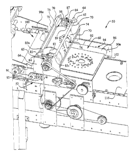
Referring now to Figs. 1 through 4, a pie forming apparatus of one'
embodiment of the present invention is shown and generally designated with
the numeral 50. Throughout the description, the pie top forming apparatus 5G
will be alternately referred to as the pie top former or the apparatus. The
apparatus 50 generally includes: a frame 52 mounted to the main frame of
n;
pie making machine or assembly line for supporting the apparatus 50; a cove
or guard 54 mounted to the frame for protecting a user from the rotatin j
components of the apparatus; a cylindrical die 56 having an image surface 7r~
rotatably attached to the frame 52 for forming an image in a top sheet of pip
dough; a counter surface such as counter roller 58 rotatabty mounted to this
frame 52 and adjacent to and slightly spaced from the die 56 for providing
resistance against the image surface white forming images in a top sheet c:~
pie dough; a pie top conveyor 60 rotatably attached to the frame 52 fag
transporting tap sheets of pie dough between the die and counter roller t~t~
form an image in the pie top dough; and a drive system 62 for driving anii5
rotating the rollers and the die 56 in the apparatus 50. j
More specifically, the frame 52 is made out of a suitable material such
y
as stainless steel or aluminum and provides the structural support for the pig
forming apparatus 50. The frame includes two side frame panels 64, whid~
are attached directly to the mainframe of the pie manufacturing machine using
suitable attachment devices. The side frame panels 64 of the, pie formir~
apparatus are of suitable size and thickness to support the pie forming
apparatus 50. Two support bars 67 extend between the side frame panels ,
and are welded or otherwise secured to the inner surface of each side frarr#e
0
13
h
CA 02401536 2002-09-06
~l
l
r.
H
panel. Each panel includes an opening for mounting a die shaft tensioner 84.
Ridges 65 are formed in each side frame panel to slidingly engage the.Y
a
tensioners 84. Furthermore, two receptacles 64a and 64b are formed in each ~;
side frame pane) to enable a support bracket 85 to be mounted to each side
frame panel. ~a
The cover 54 mounts on the top of the pie forming apparatus 50 andi"
,;
protects a user from getting injured by the rotating components of the pier
forming apparatus 50. The cover 54 is made of a suitable material such asl~
stainless steel and is attached to the side frame panels 64. The cover 541;
includes two side cover panels 66, and a plurality of support bars 70. The'
side cover panels 66 are attached to the side frame panels 64 by suitable;
fasteners. The side cover panels 66 are attached to the side frame panels 6
and cover an upper portion of the side frame panels. A plurality of suppo
bars 70 extend horizontally between the side cover panels 66 and arE3
attached to each side cover panel. Support bars 70 are attached to the sid .~
cover panels 66 by suitable fastening devices. The top cover panel 68 is;
attached to the support bars 70 and extends from the inlet side of the die 56'
to the outlet side of the die. The top cover panel 68 covers almost the
entirE~
surface of the die 56 except for two rectangular openings behnreen the bottom
of the cover and the surface of the pie top conveyor 60. One opening is ors
the inlet side of the die 56 to enable the pie top dough to be fed between th
die and the counter roller. The other opening is located on the outlet side dl
the die to enable a sheet of pie dough having a formed image to exit the diE~
r
56 and to be transported to a corresponding pie bottom by the pie tomb
conveyor.
The cylindrical die 56, which is alternatively referred to as the image
die, the rotating die or the die, forms an image in a top sheet of pie
dougl~r.
The die 56 is rotatably attached to the side frame panels 64 and extendls
y
betvreen the side frame panels and underneath the top cover panel 68. In the
illustrated preferred embodiment the die 56 is cylindrically shaped' and
rotate
about a horizontal axis 72. The die surface 74 is preferably smooth except
fcir
an image surface 76 which is molded, attached or otherwise formed onto car
14 l
I.
Ii
CA 02401536 2002-09-06
;
i.'
a
connected to the die surface 74. The image surface 76 may be any shapes,!'
patterns, symbols, designs, openings or combinations thereof as desired by~'
the manufacturer or user and as discussed in further detail below. The image
surface 76 displaces dough in a pie tap dough sheet that is fed into the pie
topic
former to form an image in the dough that forms the top of a pie. The died,;
surface 74 and image surface 76 may be made of any suitable material such~r
as a polished or smooth material. The die surface 74 and image surface 76~
are preferably smooth and made of a non-stick material so that the dough'
,.
does not stick to either surface. Preferably, a smooth material such as
a
nickel based metal or TFE based surface is used to form the smooth non-stick;
surfaces of the die and image surface. However, it should be appreciated tha~
any other suitable smooth non-stick surface material may be used for these
y
surfaces. The die 56 also includes a guide 75 which extends horizontall~l
a
along the surface of the die 74. The guide 75 extends vertically from the die
~s
surface 74 and enables a user to align a pie top dough sheet to be fed into
apparatus 50.
The cylindrical die 56 is substantially hollow so that die shaft 78 can b~a
extended through the interior of the die as shown in Fig. 4B. The die shaft 7
h
extends through the openings in the bearing units 87. An index and control
dial enable a user to adjust the synchronization of the cylindrical die 56 ani
the pie top conveyor 60. In this manner, a user can adjust the placement of ;~
formed image on a top sheet of pie dough. On one end of the die shaft 78, an
index 200, dial 201, fifth gear 128 and bushing cap 202 secure the shaft enib
in place. The index 200 and dial 201 include circular openings which enabll
the index and dial to be placed onto the shaft end. A user turns the dial
20I;h
to establish a specific rotational angle for die 56, which adjusts the
ptacemec~lt
of the image surface 76. The adjustment positions the image surface to forr~n
.a
an image at a particular position on the top sheet. of pie dough. The fifth
gear
128 also slides over the end of the die shaft and is secured to the shaft
wilih
bushing cap 202. The bushing cap is attached to the fifth gear 128 ~y
suitable fasteners. As explained in further detail below, a drive belt, dri~~e
chain or independent drive turns or drives the fifth gear 128, which toms t ie
I'
.:
I
CA 02401536 2002-09-06
Ij
i8
die shaft 78. '
A die shaft 78 attaches to the cylindrical die 56 and ratates the diet'
.s
during operation of the apparatus 50. The die shaft 78 also supports the die;y
56 above the pie top conveyor 60. The die shaft 78 is fixedly attached to the'
cylindrical die 56 so that the cylindrical die rotates as the die shaft
rotates~l
about the horizontal axis 72. Two end plates 80 are fastened to each end o~"
the cylindrical die 56 to seal the interior of the die. The end plates 80 ar~~
fastened to each side of the die by suitable fasteners. The die shaft 78'
extends through openings in each end plate 80 and to the corresponding
bearing units 84. Two shaft fastening plates 82 extend over each end of them
shaft through openings in the middle of each fastening plate 82. The diameter
of the openings on the shaft fastening plates 82 correspond to the diameter
o'=
the die shaft 78. The shaft fastening plates 82 attach to the die shaft 78 ors
each side of the cylindrical die 56 and secure the die shaft to the
cylindrical]
die by fastening to the end plates with suitable fasteners.
The cylindrical die 56 having~image surface 76 forms an image in a pied
top dough sheet by embossing, displacing, pressing or voiding the image o''
i
opening in the sheet. Different images or openings require different levels v~
tension between the die 56 and a sheet of dough. The die shaft te~nsioners
8s:~
n
control the tension by raising or lowering the die 56 above the pie toy
conveyor 60. Two die shaft tensioners 84 are siidingly attached to the sid~p
frame panels 64 on each side of the cylindrical die 56. The shaft tensioner
84 are positioned in the openings formed in each side frame panel 64. Each
tensioner 84 includes a support bracket 85 that defines circular openings 85~,
85b and 85c that extend through the support bracket. The two end openings
85a and 85c correspond to receptacles 64a and 64b on each side frarri
panel 64. Suitable fasteners are used to secure the support brackets 85 i~o
the side frame panels 64. A tension rod 86 extends upward through tti~
middle opening 85b of each support bracket 85 and through tf~~
corresponding receptacles 64a and 64b in each support bracket 85 ris
illustrated in Fig. 3. Each tensioner 84 includes a bushing 88 and insert 81~.
The insert 89 slides into an opening in bearing unit 87. The tension rod :~6
II
16
I
Iq
i::
--.--~_____
CA 02401536 2002-09-06
r
extends down through a corresponding opening in bushing 88 and insert 89. ~a
~.
A suitable fastener such as a threaded nut secures the tension rod to insert
Ii
89. The insert 89 is placed into bearing unit 87, The support bracket 85,
tension rod 86 and bushing 88 attach to the bearing unit 87. Each bearing,
unit 87 includes a pair of channels 87a and 87b. The channels slide over theli
ridges 65 on side frame panels 64 to enable the tensioners 84 to move up orl?
down within the side frame panels.
n
The tensioners 84 enable a user to raise or lower the die shaft 78 andly
cylindrical die 56 to apply the proper tension between the image surface 76~,
and a pie dough sheet. The tension between the image surface 76 and pier
top dough determines at least, in part, the amount of displacement necessarjl:
to form a particular image in the pie dough with particular dimensions'
including depth or height of the image with the image surface 76 on the
cylindrical die 56. The bottom of each tensioner 84 receives each end of the
~a
die shaft 78 through corresponding holes. Bearings (not shown) are place'
around the ends of the die shaft 78 to enable the die shaft to rotate withir"5
r.
each tensioner. ;,
A pie top conveyor 60 is positioned beneath the cylindrical die 56 anc'
befween the side frame panels 64 on the frame 52. The pie top conveyor 661
transports a top sheet of pie dough between the cylindrical die 56 and the
counter roller 58. Once an image is formed in the dough the pie top
conveyo°
transports the pie dough having the formed image to be placed on
corresponding pie bottom. The belt 92 rotates about a pair of rollers 90a an~~
90b to transport sheets of pie dough to the cylindrical die 56. Two conveya:~
25 or plate rollers 90 are rotatably attached to the frame 52 on each side of
the.
cylindrical die 56. The inlet roller 90a is mounted near the inlet of th~
p
cylindrical die 56. The exit roller 90b is positioned near the outlet of the
cylindrical die. The rollers 90 extend between the side frame panels 64 an~
are rotatably attached to the panels so that the rollers can rotate in ~~
I
clockwise direction with respect to the frame 52 as a person looks ax the
apparatus 50 from the side of the apparatus where the inlet to the die 56 is
qh
the person's left hand side. It should be appreciated that the die rotates in
~I
17
Ii
i
N
I!
CA 02401536 2002-09-06
,1
I~
clockwise direction if a person viewed the die from the opposite side of the
la
apparatus 50. The inlet roller 90a includes a bearing 91 and support bracket
~~
93. The bearing 91 enables the roller to rotate inside frame panel 64. Also.
bearing 91 can be adjusted to increase or decrease the tension in the pie top
5 conveyor 60. The support bracket 93 mounts to the side frame 64 and
stabilizes the bearing 91. y
A conveyor belt 92 extends around each roller 90 forming a closed ioopl
about the rollers. The conveyor belt includes an inner surface 94 and an
outer surface 96 and is made of a substantially non-compressible, nonstick:
smooth material. The conveyor belt 92 minimizes downward displacement ot~.~
the belt during the forming of an image on a pie top dough sheet!':
Furthermore, the smooth material used to form the belt surface helps tc~'
prevent the pie dough from sticking to the belt, It should be appreciated
that;
any suitable substantially non-compressible, smooth non-stick material ma~~
be used to form the conveyor belt. The inner surface 94 or the conveyor bell
92 frictionally contacts the surfaces of the rollers 90 to prevent the belt
frorn~
.Y
slipping off of the rollers and so the belt moves in unison with the movemene
of the rollers.
i
As illustrated in Figs. 1 and 2, a slider 98a is attached at the inlet side
of the pie top conveyor 60 and a slider 98b is attached to the outlet side of
the
conveyor for enabling the pie dough to be transferred to and from the pie
~to~i
conveyor 60. The inlet side slider 98a enables the pie dough to be transferred
from a feeder to the pie top conveyor 60. The outlet side slider 98b enabiei
~4
the pie dough having the formed image to be transported from the pie top
conveyor to a corresponding pie bottom that includes the pie tin, pie crust
and
pie frlling for the pies. Each slider surface is manufactured of a suitably
material such as stainless steel, and has a smooth surface to promote th~
sliding of the pie dough across the panels.
The image die 56 and the conveyor 60 may be driven by any suitabl~',~
drive system. For instance, as generally illustrated, the drive system mad
include a series of gears and belts which rotate the die 56 and, the pie tc~
conveyor 60. It should be appreciated that the drive system coulee
18
r;
CA 02401536 2002-09-06
i'
1
alternatively include suitable chains, intermeshing gears or any other
suitable !.
interacting or independent drive mechanisms. The image die 56 and the p
conveyor 60 may alternatively be independently driven by suitable individual
drive mechanisms or by the drive mechanism associated with main pie
making machine. '
Referring now to Figs. 5 through 7, the image cylindrical die 56 is~
i.
shown in isolation along with a sheet of pie dough. The sequence of figures~j
shows an image of an apple being formed in the sheet of pie dough. As cane
be seen, the raised image surface of the die forms the image of the apple
that~i
is pressed into the dough as the die is rotated past the dough. According toiy
the present invention, the die forms the image by displacing the dough in the
area of the image rather than cutting the image from the dough. The die may'
also emboss, press, displace or void an image or opening in a sheet of ply
dough.
Referring to Figs. 5A and 6A, in the embodiment, the die 56 rotates in
counterclockwise direction to rotate the apple image i38 towards the pig;
dough 51 to form the image in the sheet of dough. The sheet of dough 51 i
r.
fed into the inlet side of the die 56 and moves between the die 56 and the
pigs
top conveyor 60. t?irectly beneath the central axis 72 of the die 56 is ~'
counter su fj
pport or surface such as the counter roller 58 which is rotatabl~f
.;
mounted beneath the pie top conveyor 60 as shown in Fig. 6A. The counte%
roller 58 provides a restriction or a resistance to the inner surface 61a of
the
I,
pie top conveyor 60 so that the image can be formed in the sheet of dougf~
while minimizing the downward displacement of the pie top conveyor. As the
die 56 rotates in a counterclockwise direction, the image surface rotate~~
r:
towards the sheet of dough 51 as the sheet of dough is being fed into the
inle#
side of the die. The die 56 is positioned so that the horizontal axis 72 of
thin
5
die is directly aligned above the horizontal axis 59 of the counter roller a
illustrated in Fig. 6A. ''
I'
Referring to Figs. 58 and 68, the cylindrical die 56 rotates the image
surface 76 so that the front edge of the apple image 138 contacts the sheet
~'f
dough 51 directly above the horizontal axis 59 of the counter roller 58
~a
19 jY
In
CA 02401536 2002-09-06
i
i
Ii
.;
illustrated in Fig. 6B. The tension of the counter roller 58 enables the
apple'
image 138 to be firmly pressed into the pie top dough sheet 51. Because thef
apple image 138 is concentric with or curves about the surface of the die 56,'
i
only an edge or small cross-section of the image surface contacts the sheet
ofd;
dough at any given time. The pressure of the counter roller 58 underneatJ~'i
the pie dough 51 and the apple image 138 on the top surface of the pie doug ~'
displaces the dough at the contact point and towards the inlet of the die 56.
Irk;
i:
this embodiment the image surface fully displaces a complete section ot-''
dough from the pie dough sheet as illustrated in Fig. 7A. The direction of the
displacement of the pie dough by the image surface is shown by the arrow'
la
on the surface of the pie dough. The image surface does not cut the image
from the dough, but displaces the dough uniformly within the pie dough sheet'
n
Therefore the image is formed without wasting dough. Referring to Fig. 5C.
and as further illustrated in Fig. 6E, the apple image 138 has been formed
anc~~
the die has rotated clear of the dough. The pie dough may then by
transported from the cylindrical die 56 by the pie top conveyor 60.
In one embodiment, the pie fop conveyor 60 includes a conveyor bell
that is smooth, non-stick and substantially non-compressible. The none
compressible characteristic of the conveyor belt decreases the downward
displacement of the conveyor as an image is being formed in a top sheet q~
pie dough. The belt enables an image to be formed clearly and distinctly in
top sheet of pie dough and prevents the pie top dough from sticking to th~
conveyor. It should be appreciated that the pie dough may be transported
without the conveyor belt 60. The pie dough may be extended over a pluralit~r
of rollers and fed between the die 56 and counter surface 58 or transporterii
using any other suitable device or method.
Referring now to Figs. 6A through 7C, a cylindrical die 56 having a~
image surface 76 is illustrated where the die displaces an image into a pig
dough top with an image surface. The image in this embodiment is partially
I,
displaced from the dough sheet as illustrated in Fig. 7B. It should
appreciated that an image or opening may be formed in a top sheet of p~
dough by embossing, pressing, displacing or voiding the image or opening a ~
a
1
,:
I
~y
j',
I:
CA 02401536 2002-09-06
the pie dough. Referring to Fig. 6A, a non-continuous pie dough top or shee
of pie dough 51 is fed into the inlet side of the cylindrical die. The
cylindrica
die 56 is tensioned so that the image surface on the die contacts the pit:
dough at a point and level directly above the horizontal axis of counter rolle
58. As the pie dough sheet 51 is fed into and between the cylindrical die 5 .
and counter of the roller 58, the image surface 76 on the cylindrical die
rotate;
towards the pie dough sheet. The pie top conveyor 60 moves the pie dougf~
towards the cylindrical die and counter roller, as shown by the arrows on the;
pie dough. The pie top conveyor 60 and more specifically the counter rolled
58 adds resistance to the lower surface of the pie top conveyor to minimiz
the downward movement of the conveyor as an image is being formed in then=
w'
surface of the pie dough.
s
l he cylindrical die 56 having image surtace 76 contacts the pie doug~i
top at a first edge or portion between the cylindrical die and the pie to~
conveyor 60 as illustrated in Fig. 6B. The cylindrical die 56 rotates at a
spee~9
that enables the image surface 76 to contact the pie top dough at the propt~t
location on the pie top dough to form the corresponding image on the surface
of the pie dough. The pie dough top continues to move towards the outlet c~
I:
the cylindrical die 56 as the image is being formed.
Referring to Fig. 6C, a middle portion of the image is formed in the piE
,,
top dough. This portion is formed against the surface of the conveyor belt.
should be noted that only a small area of the image surface contacts the pi
dough at a given time. The sma(I point of contact enables the counter rollsir
58 to precisely apply pressure to the pie top conveyor 60 at the exact point
c~f
contact by the image surface. The pie dough top continues to move on thh
pie top conveyor 60 towards the outlet of the cylindrical die.
Referring now to Fig. 6D, the bottom portion of the image 'is formed air
l;
displaced in the pie dough top. The cylindrical die 56 continues to rotate in
~t3
counterclockwise direction and releases or moves the image surtace awi~~
from the pie dough after the image is formed. It should be appreciated that
any type of image may be formed in the pie dough top such as shapej~,
characters, symbols, geometric configurations, letters, openings, numbers c5r
21
n
w
..
CA 02401536 2002-09-06
;S
other designs, patterns and combinations thereof as well as any renderings. i
a
Referring to Fig. 6E, the image is completely formed or displaced in they
pie top dough top and the pie top dough moves or exits the outlet of thej'
cylindrical die 5G. The image is now formed on the pie dough top and the pie'p
dough top can be placed onto a corresponding pie bottom to form a complete;
pie. It should be appreciated that the pie bottom includes any components o
the bottom portion of a pie including but not limited to the pie tin, pie
crust anc~;
pie filling. Preferably, the counter roller 58 and the pie top conveyor both
form
a restriction against the image surface 76 in an apparatus 50. iF
Once an image is formed, the image surface 76 on the cylindrical die'
56 continues to rotate in a counterclockwise direction to engage another pig;
top dough sheet that will be fed into the inlet of the cylindrical die 56
between
the cylindrical die and the counter roller. Preferably, the pie top dough
sheet
are continuously fed so that multiple pies may be made using the pie forminci
apparatus 50. It should be appreciated, however, that any reasonably
number of images may be formed in a sheet of pie dough or that any numbed
of pie tops may be manufactured with the pie forming apparatus of th~i
present invention, whether it be continuous motion of individual sheets of
pig;
dough, continuous motion of continuous sheets of pie dough, start and stoma
20 motion of individual sheets of pie dough or start and stop motion of
continuous
~i
sheets of pie dough.
The images may be formed in a top sheet of pie dough by displacin~~
an entire thickness of pie dough, a partial thickness or amount of pie
dougEfi,
or multiple displacements of pie dough. Referring now to Figs. 7A, 7B and
7C, various embodiments of the present invention are illustrated where
different amounts of dough are displaced from a top sheet of pie dough. I'
Fig. 7A, the complete section or the entire thickness of pie dough is
displace"
by the image that is formed in the top sheet of pie dough. In Fig. 7B, a
partial
amount of pie dough is displaced from the top sheet of pie dough. In Fig. 7
~f,
~,
multiple sections or portions of the pie top sheet of pie dough are displaced
Ely
multiple image surtaces on the cylindrical die 56. It should be appreciate
that any suitable number of pie dough sections may be displaced using one cir
~l
22 i
.;
,,
CA 02401536 2002-09-06
IC
more image surfaces on a cylindrical die 56. For example, in Fig. 7C the pie
dough sheet is displaced in two different sections on the dough. The imagey
surface 76 rotates and contact the pie dough sheet in two different locations
j;
on the sheet. The resulted pie dough sheet is formed having a raised surface;
portion on the pie dough sheet.
Different images may be formed in the pie top dough sheet by inserting:
dies having different image surfaces. A user therefore, can create pie tops
having a custom image. Referring to Figs. 8A through 8D, alternative
embodiments of the pie forming apparatus 50 of the present invention area;
illustrated where different images are formed in the pie top dough. In Fig.
8A;
a star image 152 is formed in a pie dough top. The star image is formed irr~
the same manner as described above as the cylindrical die 5fi having the star,
shaped image surface is placed into the pie forming apparatus 50 to form they,
star image 152 on the sheet of pie dough 51. Once the star image 150 i
formed in the pie top, the pie top proceeds to be placed onto a correspondin
j'
pie bottom 148 to form a complete pie. In Frg. 8B, a letter image 153, th~~x
c
letter "O," is formed on the pie top. Similarly, in Fig. 8C, a circle image
154 i I':
formed on the pie dough top 51. tn Fig. $D, a lattice pattern is embossed anal
voided from the pie top dough. It should be appreciated that any images such
as shapes, characters, letters, numbers, symbols, geometric configuration;
designs, patterns or combinations thereof may be formed on a pie top usin~j
the pie forming apparatus 50 of the present invention. The cylindrical die 5ko
it
is removably attached to the pie forming apparatus frame so that different
image surfaces 76 on different cylindrical dies 56 may be interchanged into
~,
pie former 50 to form different images on pies as desired by a user. The user
of the present invention can quickly and easily change image dies or rollers
t~
change the images on the pies.
Some pie top images which are complex will require multiple levels
be formed in the pie top dough sheet. Therefore, in another embodiments tw~
pie top forming apparatuses 50 are aligned in series for displacing different
components of a complex image or for displacing different levels of a multiple
level image. Referring now to Fig. 9, a further embodiment of the presei~rt
la
23
,
la
~s
CA 02401536 2002-09-06
,V
~!
invention is iilustrafed where two identical pie formers 50 are attached in'~
series to a frame. In this embodiment, each pie forming apparatus 50 ~;
f~
displaces a portion of an image on pie dough 51. By displacing a smalleri
portion of an image using two cylindrical dies 56, a complex or distinct
image;
may be formed in the pie dough top 51. The cylindrical dies 56 (not shown);
are attached to the frame so that each die is positioned over a single pie
tope
conveyor 60. The drive system (not shown) far the dual cylindrical die system,
changes slightly so that one belt 156 drives both cylindrical die units. Bye
:t
having a single drive belt, both die shafts 78 of the cylindrical dies in Fig.
10t
rotate at the same speed to enable an image to be properly formed in a sheen,'
of pie dough top 51, l
In this embodiment, a pie dough sheet 51 is fed into the inlet of the firs
cylindrical die ~6a and the pie dough sheet 51 moves between the first'
cylindrical die 56a and the first counter roller 58a as the first portion of
ark
image is formed on the pie dough top sheet 51. As the pie dough top shee
51 with the first portion of the image formed on its surface exits the firs
cylindrical die 56a, the sheet then enters the second cylindrical 56b die at
itsy
inlet. The sheet then passes between the second cylindrical die 56b and they
second counter roller 58b as a second portion of an image is formed on the
surtace of the pie dough sheet 51. Once the second image is formed on the
pie dough sheet surface, the completed image is formed on the pie dough anew
the pie dough sheet 51 exits the second cylindrical die 56. This embodimeri
illustrates a continuous motion or feed system where a non-continuous sheC~
of pie dough is fed into the apparatus 50. It should be appreciated that
n
continuous or individual sheet of pie dough may be used and a continuous o~
t
non-continuous motion or feed system may be used in the apparatus 50. la
The pie dough sheet 51 is then transported by the pie dough toga
conveyor 60 until it is positioned onto a corresponding pie bottom on a lower
conveyor (not shown). !t should then be appreciated that having the two ~r
t,
more pie formers in series enables complex images to be formed in th;~
surface of a pie dough top and multiple images to be formed on a pie to~.
One example is if two separate circle images are to be placed on a pie toga
24
I'
r:
~,i
CA 02401536 2002-09-06
1
t
surface. One circle could be formed into the pie top surface by the first,;
cylindrical die 56a and then the second circle may be placed in the pie top iy
surtace by the second cylindrical die 56b a small distance from the first
circle ~'
image. Each cylindrical die, 56a and 56b, and corresponding image surfaces, I
;,
76a and 76b can be manufactured with a smooth, non-stick material so that.'
the pie dough does not stick to either image surface. 76a and 76b, during i,
formation of the image in the pie dough.
Referring now to Figs. 10A through 10E, an exarnple of how an imagel.
is formed by the dual cylindrical die system having separate image surfaces
is~i
shown. Each cylindrical die, 56a and 56b, is positioned over a correspondingly
counter roller, 58a and 58b, so that the horizontal axis of each cylindrical
die
is positioned directly above the horizontal axis of each counter roller. This"
enables each image surface, 76a and 76b, to contact the pie dough top at a~
point directly above the point of resistance by the counter rollers. ~i
Referring specifically to Fig. 10A, a pie dough sheet 51 is fed into this'
h
embodiment of the pie forming apparatus. The pie dough sheet 51 enters the;
inlet side of the frst cylindrical die 56a and moves between the die and they
counter roller 58a. As the pie dough sheet moves into the inlet side of the
firs
l
cylindrical die 56a, the image surtace 76a on the first cylindrical die is
rotaflnat
.,
in the counterclockwise direction toward the position on the pie dough sheef
where the image is to be formed. The image surface 76b on the secon
cylindrical 56b die is also rotating in a counterclockwise direction and i~!
positioned so that the second image surface 76b will contact the pie dough
top sheet 51 at the proper position on the pie top surface. It should bed
25 appreciated that the cylindrical dies may be adjusted so that image
surfacezp
n;
may contact the pie dough top surface at any position on the pie top surface
n;
as desired.
Referring to Fig. 10B, the first image surface 76a on the first cylindric
die 56a contacts the pie dough top sheet 51 at a point directly above th;>~
central horizontal axis of the first counter roller 58a. This minimizes th~9
downward displacement of the pie dough top conveyor so that a more distine~t
and exact image may be formed in the pie dough top surface. The pie doug;
.'
r
,,
n
CA 02401536 2002-09-06
I°
11
ih
top sheet 51 moves towards the inlet of the second cylindrical die 56b as the
!~
first cylindrical die 56a begins to form the image in the pie top surface. !4
Referring to Fig. 1 OC, the pie top, having the first formed image in its ~'
surface, exits the first cylindrical die 56a and begins to enter the inlet
side of lj
the second cylindrical die 56b. The second image surface 76b on the second .'
w;
cylindrical die is rotating in a counterclockwise direction to position the
second j.
image surface 76b at the proper or desired location on the pie dough top
~a
sheet.
Referring to Fig_ 10D, the second image surface~76b contacts the pier'
r
dough top sheet surface at a point directly above the horizontal axis of the'
second counter roller. Similar to the first counter roller, the second
countern~
roller applies resistance to the pie top conveyor 60 so that the downward'
displacement of the conveyor is minimal, and thereby enables the image~4
surface to form a distinct image in the pie top surface. As shown in Fig.
10D,!
r:
the second image being formed in the pie top surface is overlapping the first
image that was formed by the first cylindrical die and image surface. It
should;
be appreciated that any type of one or more images may be formed oq
displaced in a pie top by the dual cylindrical die system.
I;
Referring to Fig. 10E, the sheet of pie dough 51 having the formed:
image exits the second cylindrical die 56b. The second image surface 76twb
rotates away from the sheet of pie dough and rotates to meet a second of
subsequent sheet of pie dough that is fed into the pie forming apparatus''
Once the image is formed in the sheet of pie dough, the pie dough will b~~
transported by the pie top conveyor 60 until it is placed on a correspondin,;
pie bottom located on a lower conveyor. j,
In an embodiment of the pie forming apparatus of the preser
invention, two or more image surfaces are placed onto one die 56. Referrina~
to Fig. 11A, two image surfaces 76 form corresponding images in the pie tolh
dough 51 on conveyor 60. The dual image apparatus produces twice th~
amount of pie tops that the single image surface apparatus can produce,.
Furthermore, different image surfaces may be placed on the die 56 so that
two different pie tops having different images may be formed simultaneously".
26
.,
..:
a
.3
CA 02401536 2002-09-06
r
I
l
Therefore, the pie top forming apparatus 50 can be used to mass produce ~a
several pies having custom-looking pie tops.
Referring now to Fig. 1 iB, a further alternative embodiment of the pie y,
top forming apparatus of the present invention is illustrated where two pie
formers 50 are placed side by side. This embodiment illustrates how one or"
more pie top formers can be placed in a pie manufacturing assembly fine so~
that several more pie tops may be manufactured by a user. Each pie formingls
apparatus operates as described above and forms pie tops having the same
or different images. It should be appreciated that the same or different
l,
images may be formed by each pie forming apparatus as desired by user.
Referring now to Fig. 12, a further ~altemative embodiment of the pie'
forming apparatus of the present invention is illustrated where the image!'
surtace 76 has release edges or surfaces 158 that enable the image surface;
to better release from the sticky pie dough. Furthermore the release edges'
158 cause more consistent displacement of the pie dough because the dough'
is less likely to stick to the die surface and create imperfections in the pi
c
dough. The release edges 158 are formed at an angle or are beveled so th
J
there is a smooth and gradual surface that contacts the pie dough top Burin ~~
formation at any given time. The gradual or angled surface eliminates sham!
,:
points or edges which are more likely to stick to the pie dough. The release
edges 158 also enable the image surface 76 to pull away from the pie doug>f
top surface after formation. Preferably, the release edges 158 are combine's
with the smooth or non-stick surtace of the image surface so that sticking i;~
minimized. As shown, the release edges 158 form a corresponding surfaces
160 in the pie top surface so that upon completion the image formed in the pi
top will have a similar edge as shown in Fig. 12 where the edges are angle
or beveled.
Referring now to Fig. 13, in still a further alternative embodiment of
present invention, a heater 162 is attached to the interior 164 of the
cylindric
die 56. The heater heats the cylindrical die surface 166 and the imag
surface 78 on the cylindrical die. The heated cylindrical die surface 166 an
r;
corresponding image surface 76 heats the pie dough 51 when the surfac;
27
i7
~,
~.
I,
,,.
CA 02401536 2002-09-06
i'
fv
I'
contacts the pie dough. The heat from the surface of the cylindrical die heats
~
the pie dough and melts the fat in the layer of the pie dough adjacent or ~
engaging the die. The fat acts as a lubricant or film between the pie dough
top and the cylindrical die surface 166 so that sticking of the pie dough to
the.'
cylindrical die surface is minimized. Electrical leads on the heater are!e
i.i
attached to electrical wiring which connect the heater to an outside
electricall'
source through the interior area 168 of the die shaft 78. The electrical Leads
and wiring are suitably manufactured so that the leads, wiring and heaters
area
able to rotate as the cylindrical die and corresponding shaft rotate. The?
electrical wiring connects to an electrical contact 170 located outside of
they
cylindrical die 56 and on the frame of the pie forming apparatus 50. The;
contact 170 attaches to the end of the die shaft 78 and provides an
electrica~~
current from a power source to the electrical wiring.
Referring now to Fig. i4, another alternative embodiment of the pig:
forming apparatus of the present invention is illustrated. A compressed ga~j
such as nitrogen or air is supplied by a compressor or similar device (nof
shown) tv die 56. The gas is transported through suitable tubing to they
interior of the hollow die shaft 78 that supports the cylindrical die. The
ai~°
moves through the die shaft 78 and is pressurized so that the air is forced
oul
of openings 174 formed in the die shaft. Then, as the air passes into the:
interior of the cylindrical die 56, the pressure of the air causes the air to
mover
out of openings 176 formed in the cylindrical die surface 166. As the ai'T
pushes out of the openings 176 of the cylindrical die surface, it pushes;
against the pie dough and enhances the release of the pie dough from the
cylindrical die surface 166. In an alternative embodiment, the compressed
gas is blown onto the outer surtace of the die 56 from tubing or a simile
device that is located adjacent to the point where the die surface contacts
the
pie top dough. The force of the compressed gas pushes the pie top dough
from the die surtace as the pie dough exits from between the die and counter
surface.
It should also be appreciated that any type of gas that promotes th
release of the image surface from the pie dough may be used in this'
I:
28
;,
i
CA 02401536 2002-09-06
G
~a
t
embodiment. In other embodiments, the non-stick surface features of the die ~
and pie top conveyor are combined with the release edge feature of the image;i
surface. It should be appreciated that apparatus may include each of they
non-stick features including the release edge feature independently, anyi
combination of the non-stick surface features including the release edge:
feature, or all of the non-stick surface features including the release edge
feature.
The thickness of the pie top dough can be adjusted to accommodat
.,;
different image surfaces that form images with varying displacement depths in
the pie dough. In one embodiment, the pie dough Thickness is increased od,~
decreased uniformly across the entire sheet of pie dough to accommodate alb
particular image surface.
f n an alternative embodiment, the thickness of the pie dough can b
adjusted so that the thickness is not uniform across the sheet of pie toG;
dough. Referring now to Fig. 15, an alternative embodiment of the presen
invention is illustrated where the sheet of pie dough 51 is modified so that
onEv
edge 178 of the pie dough sheet is raised or elevated and gradually slopes;
downward to a tower edge 180. The configuration in this embodiment of the>
h
pie dough sheet resembles a wedge-like shape and preferably, the elevates;
I,
edge 178 of the pie dough sheet is fed into the inlet side of a cylindrical
dig
first. The raised or elevated portion of the pie dough top sheet will b
displaced towards the lower edge 180 of the pie dough top sheet. Therefore
the pie dough will be evenly and uniformly displaced while forming an image
in the pie top. In operation, the elevated edge 178, which has a greater
quantity of pie dough, is displaced towards the lower edge 180 the pie dough
sheet. As the raised or elevated surface 17$ of the pie dough sheet i
a
displaced, it fills or adds to the lower area or edge 180 of the pie dough
sheep
I
and uniformly levels the pie dough sheet. .
r
Referring now to Fig. 16A through 16C, an example of the alternativla
embodiment of Fig. 15 is illustrated where the wedge-shaped pie dough she ~~
51 is fed into the inlet of a cylindrical die 56 in a pie forming apparatus 50
c~f
the present invention. Referring to Fig. 16A, the cylindrical die 56 rotates
in
29
CA 02401536 2002-09-06
I
a
f,
i
i
countercfock~nrise direction as described above and the image surface 76 of
the cylindrical die rotates towards the pie dough sheet 51 to contact the
sheet=
i~
at a point above the central horizontal axis of the counter roller 58.
Referring to Fig. 168, the image surface 76 contacts the pie dough(
sheet 51 at the point adjacent to the counter roller 58 and displaces an
imagej'
in the pie dough. The raised surface or edge 178 of the pie dough sheet 51
is~~y
displaced towards the lower surface or edge 180 of the pie dough sheet. Thej
r,
arrows on the pie dough sheet show the movement of the pie dough as it is
being displaced by the image surface 76.
Referring to Fig. 16C, the complete image is formed in the pie dougf~l
sheet 51 as the image surface 76 rotates away from the sheet. The pig
dough sheet 51 exits from the die 56 having a formed image. Furthermore~s
the resultant pie top has a more uniform or evenly displaced surface because
the dough on the raised surface side of the pie dough sheet was displaced
'.
towards the lower surface 180 on the sheet.
!;
The pie dough can be released from the image die surface using ~i
non-stick material such as cheese cloth that forms a porous barrier betvvee~
the pie top dough and the image die surface. Referring now to Fig. 17, the;
cheese cloth or similar material 300 extends about two rollers 301. ThE
rollers 301 rotate the non-stick cheese cloth 300 between the die 56 and the:
pie top dough 51. As the image surface 76 rotates and engages the pie toj~
dough 51, the cheese cloth is pressed into the pie dough by the image
surface. The cheese cloth molds tv the image surface 76 so that the image
formed in the pie dough 51 is not affected by the presence of the cheese clot
25 between the die and the pie dough. When the pie top dough 51 having th~~:
n
formed image exits the die 56, the cheese cloth prevents the pie dough fror'
sticking to the die. Instead the pie dough, which is contacting the non-sticsc
cheese cloth, releases from the cheese ctoth and remains on the pie top
conveyor 60.
c
In another alternative embodiment which is not illustrated, a scraper a1r
similar device prevents the pie top dough from sticking to the cylindrical
di~.
The scraper is an elongated planar device that has a top and bottom edgy:.
i;
~t
Ill
I'.
~I
CA 02401536 2002-09-06
:'
The scraper is preferably mounted to the frame and adjacent to each end of~~:
the die. The scraper extends to a point near the contact area between the
die~~
and the pie dough. As the pie dough exits from between the die and counter!"
surface, any pie dough that sticks or adheres to the die surface contacts they
scraper and releases from the die surface. The scraper therefore, scrapes one
removes the pie dough from the die surface during the forming of an image i t
the pie dough. It should be appreciated that any size and number of scraper~j
n
may be used to promote the release of the pie dough from the die surface.
It should be understood that various changes and modifications to th~~
presently preferred embodiments described herein will be apparent to those
skilled in the art. Such changes and modifications can be made without'
departing from the spirit and scope of the present invention and withoul~
diminishing its intended advantages. It is therefore intended that suck
changes and modifications be covered by the appended claims. ~'
E;
I
r
I
a
t
Is
I
~>
t?
~i
11
If>
~1
6
31 ki
IJ
7
71
i..i