Note: Descriptions are shown in the official language in which they were submitted.
CA 02401925 2002-09-06
GAMING APPARATUS HAVING TOUCH PAD INPUT
Back rg ound of the Invention
This invention relates to a gaming apparatus for playing casino or other
games,
such as slots, poker, keno, bingo and blackjack, having actuatable switches
for
providing user input.
Conventional gaming units are typically provided with a cabinet and a gaming
display mounted inside the cabinet. A screen made of glass or plexi-glass is
typically
provided with the cabinet to prevent direct access to the display by a user.
The gaming
display may be mechanical, such as a series of stepper wheels, or may be
electronic
such as a video display that is capable of generating video images. Whether
mechanical
or electronic, the gaming display may be capable of generating images
associated with
a game, such as poker, blackjack, slots, keno, or bingo. In addition, gaming
units are
known that have a first, or primary, display and a second, or bonus, display.
The first
IS and second displays may be electrical, mechanical, or a combination
mechanical and
electrical.
Selections may be made during casino game play via user inputs. The inputs
allow a user to effect a variety of gaming alternatives, such as game type,
wager
amount, or strategic decisions. Typically, a user input is provided in the
form of a
depressable button that actuates a mechanical switch. Such buttons are subject
to
frequent actuation and use abuse, and therefore may quickly wear. In addition,
while
the buttons must be accessible to the user from an exterior of the cabinet,
they must
also be connected to the switch located inside the cabinet, and therefore only
a limited
number of areas are available for button Location. A hole must be formed in
the cabinet
for each button, increasing assembly time and complexity of the gaming unit.
Still
further, conventional mechanical switches used in gaming units typically
require a four
wire connection. As a result, gaming units having several buttons require
extensive
harnesses that are difficult to build and install, and occupy a substantial
amount of
space inside the cabinet.
The bonus display, if provided, is typically positioned in a top box located
above the primary display. Unfortunately, the buttons used to play the bonus
game are
CA 02401925 2002-09-06
-2-
typically located below the primary display with the other buttons, thereby
creating a
potential source of confusion for the user. Locating bonus game buttons in the
screen
enclosing the bonus display, while possible, would require holes to be formed
in the
screen. Consequently, the screen, which is typically made of glass, will be
weakened
and more prone to breaking, and assembly costs for the gaming unit are
increased.
As an alternative to mechanical buttons, other gaming units provide a
touchscreen for inputting user selections. Touchscreens are usable in
applications using
one or more video displays that are directly accessible to the user.
Accordingly, a
touchscreen may not be used if a mechanical display is used. Even if a video
display
is provided, the use of a touchscreen may be prohibited if the display is
enclosed
behind a screen. Furthermore, touchscreens are relatively expensive and overly
complex, and therefore less reliable.
Summary of the Invention
1n accordance with the teachings of the present invention, a gaming apparatus
may comprise a display unit that is capable of generating gaming images and a
value
input device. A touch pad assembly may be provided including at least one
touch pad
having a touch detection field, wherein at least a portion of said touch
detection field
defines a touch area and wherein a user touch in said touch area creates a
disturbance
in said touch detection field to generate' a switch activation signal. A
controller is
operatively coupled to said display unit and said value input device, said
controller
comprising a processor and a memory operatively coupled to said processor.
Said
controller is programmed to allow a person to make a wager and cause a gaming
image
to be generated on said display unit, said gaming image representing a game
selected
from said group of games consisting of poker, blackjack, slots, keno and
bingo. Said
controller is programmed to determine a value payout associated with an
outcome of
said game, and respond to said switch activation signal.
The image may represent a casino game selected from the group of casino
games consisting of poker. blackjack, slots, keno and bingo, in which case the
image
may comprise an image of at least five playing cards if the casino game
comprises
poker; the image may comprise an image of a plurality of slot machine reels if
the
CA 02401925 2002-09-06
-3-
casino game comprises slots; the image may comprise an image of a plurality of
playing cards if the casino game comprises blackjack; the image may comprise
an
image of a plurality of keno numbers if the casino game comprises keno; and
the image
may comprise an image of a bingo grid if the casino game comprises bingo.
_S The gaming apparatus may include a graphical representation for indicating
said
touch area. The display unit may be mounted inside a housing having a screen,
wherein said touch pad is positioned near an interior of said screen such that
said touch
area includes at least a portion of said screen exterior side. The touch pad
may be
supported by said screen or by a sub-panel supported independent of said
screen. The
touch detection field may comprise an electromagnetic field.
The features and advantages of the present invention will be apparent to those
of ordinary skill in the art in view of the detailed description of various
embodiments,
which is made with reference to the drawings, a brief description of which is
provided
below.
Brief DescriQtion of the I)rawin~
Fig. 1 is a block diagram of an embodiment of a gaming system in accordance
with the invention;
Fig. 2 is a perspective view of an embodiment of one of the gaming units shown
schematically in Fig. 1;
Fig. 2A illustrates an embodiment of a user input area for a gaming unit;
Fig. 2B is an enlarged front elevation view of a top portion of a cabinet
similar
to that shown in Fig. 2;
Fig. 2C is a rear elevation view of the cabinet top portion of Fig. 2B;
Fig. 2D is a side elevation view of the cabinet top portion of Fig 2B;
Fig. 2E is a side elevation view similar to Fig. 2D illustrating an
alternative
embodiment of a touch pad assembly;
Fig. 2F is a side elevation view of an alternative embodiment of a touch pad
assembly using transparent conductive film;
Fig. 3 is a block diagram of the electronic components of the gaming unit of
Fig. 2;
CA 02401925 2002-09-06
-4-
Fig. 4 is a flowchart of an embodiment of a main routine that may be performed
during operation of one or more of the gaming units;
Fig. 5 is a flowchart of an alternative embodiment of a main routine that may
be performed during operation of one or more of the gaming units;
Fig. 6 is an illustration of an embodiment of a visual display that may be
displayed during performance of the video poker routine of Fig. 8;
Fig. 7 is an illustration of an embodiment of a visual display that may be
displayed during performance of the video blackjack routine of Fig. 9;
Fig. 8 is a flowchart of an embodiment of a video poker routine that may be
performed by one or more of the gamin; units;
Fig. 9 is a flowchart of an embodiment of a video blackjack routine that may
be performed by one or more of the garr~ing units;
Fig. 10 is an illustration of an embodiment of a visual display that may be
displayed during performance of the slola routine of Fig. 12;
Fig. 11 is an illustration of an embodiment of a visual display that may be
displayed during performance of the video keno routine of Fig. 13;
Fig. 12 is a flowchart of an embodiment of a slots routine that may be
performed by one or more of the gaming units;
Fig. 13 is a flowchart of an embodiment of a video keno routine that may be
performed by one or more of the gaming units;
Fig. 14 is an illustration of an embodiment of a visual display that may be
displayed during performance of the video bingo routine of Fig. 15; and
Fig. IS is a flowchart of an embodiment of a video bingo routine that may be
performed by one or more of the gaming units.
Detailed Description of Various Embodiments
Fig. 1 illustrates an embodiment of a casino gaming system 10 in accordance
with the invention. It should ire noted that the terms "gaming system" and
"gaming
apparatus" are intended to embrace Potteries. Likewise, when referring to "a
casino
game" or "game," it is intended that these terms also include a lottery.
Referring to
Fig. 1, the casino gaming system 10 may include a first group or network I2 of
casino
CA 02401925 2002-09-06
-5-
gaming units 20 operatively coupled to a network computer 22 via a network
data link
or bus 24. The casino gaming system 10 may include a second group or network
26
of casino gaming units 30 operatively coupled to a network computer 32 via a
network
data link or bus 34. The first and second gaming networks 12, 26 may be
operatively
coupled to each other via a network 40, which may comprise, for example, the
Internet, a wide area network (WAN), or a local area network (LAN) via a first
network link 42 and a second network link 44.
The first network 12 of gaming units 20 may be provided in a first casino, and
the second network 26 of gaming units 30 may be provided in a second casino
located
in a separate geographic location than the first casino. For example, the two
casinos
may be located in different areas of the same city, or they may be located in
different
states. The network 40 may include a plurality of network computers or server
computers (not shown), each of which may be operatively interconnected. Where
the
network 40 comprises the Internet, data corrtmunication may take place over
the
communication links 42, 44 via an Internet communication protocol.
The network computer 22 may be a server computer and may be used to
accumulate and analyze data relating to the operation of the gaming units 20.
For
example, the network computer 22 rnay continuously receive data from each of
the
gaming units 20 indicative of the dollar amount and number of wagers being
made on
each of the gaming units 20, data indicative of how much each of the gaming
units 20
is paying out in winnings, data regarding the identity and gaming habits of
players
playing each of the gaming units 20, etc. The network computer 32 may be a
server
computer and may be used to perform the same or different functions in
relation to the
gaming units 30 as the network computer 22 described above.
Although each network 12, 26 i5 shown to include one network computer 22,
32 and four gaming units 20, 30, it should be understood that different
numbers of
computers and gaming units may be utilized. For example, the network 12 may
include
a plurality of network computers 22 and tens or hundreds of gaming units 20,
all of
which may be interconnected via the data link 24. The data Iink 24 may
provided as
a dedicated hardwired link or a wireless link. Although the data link 24 is
shown as
a single data link 24, the data link 24 may comprise multiple data links.
CA 02401925 2002-09-06
-6-
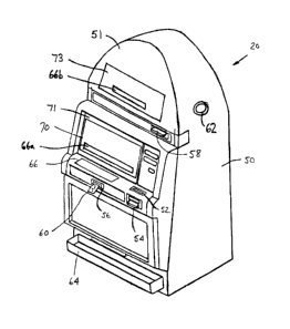
Fig. 2 is a perspective view of one possible embodiment of one or more of the
gaming units 20. Although the following description addresses the design of
the
gaming units 20, it should be understood that the gaming units 30 may have the
same
design as the gaming units 20 described below. It should be understood that
the design
of one or more of the gaming units 20 may be different than the design of
other gaming
units 20, and that the design of one or more of the gaming units 30 may be
different
than the design of other gaming units 3U. Each gaming unit 20 may be any type
of
casino gaming unit and may have various different structures and methods of
operation.
For exemplary purposes. various designs of the gaming units 20 are described
below,
but it should be understood that numerous other designs may be utilized.
Referring to Fig. 2, the casino gaming unit 20 may include a housing or
cabinet
50 and one or more input devices, which may include a coin slot or acceptor
52, a
paper currency acceptor 54, a ticket reader/printer S6 and a card reader 58,
which may
be used to input value to the gaming unit 20. A value input device may include
any
device that can accept value from a customer. As used herein, the term "value"
may
encompass gaming tokens, coins, paper currency, ticket vouchers, credit or
debit cards,
and any other object representative of value.
If provided on the gaming unit 20, the ticket reader/printer 56 may be used to
read and/or print or otherwise encode ticket vouchers 60. The ticket vouchers
60 may
be composed of paper or another printable or encodable material and may have
one or
more of the following informational items printed or encoded thereon: the
casino
name, the type of ticket voucher, a validation number, a bar code with control
and/or
security data, the date and time of issuance of the ticket voucher, redemption
instructions and restrictions, a description of an award, and any other
information that
may be necessary or desirable. Different types of ticket vouchers 60 could be
used,
such as bonus ticket vouchers, cash-redemption ticket vouchers, casino chip
ticket
vouchers, extra game play ticket vouchers, merchandise ticket vouchers,
restaurant
ticket vouchers, show ticket vouchers, ete. The ticket vouchers 60 could be
printed
with an optically readable material such as ink, or data on the ticket
vouchers 60 could
be magnetically encoded. The ticket reader/printer 56 may be provided with the
ability
to both read and print ticket vouchers 60, or it may be provided with the
ability to only
CA 02401925 2002-09-06
_7_
read or only print or encode ticket vouchers 60. In the latter case, for
example, some
of the gaming units 20 may have ticket printers 56 that may be used to print
ticket
vouchers 60, which could then be used by a player in other gaming units 20
that have
ticket readers 56.
If provided, the card reader 58 may include any type of card reading device,
such as a magnetic card reader or an optical card reader, and may be used to
read data
from a card offered by a player, such as a credit card or a player tracking
card. If
provided for player tracking purposes, the card reader 58 may be used to read
data
from, and/or write data to, player tracking cards that are capable of storing
data
representing the identity of a player, the identity of a casino, the player's
gaming
habits, etc.
The gaming unit 20 may include one or more audio speakers 62, a coin payout
tray 64 and a display unit 70 for displaying images relating to the game or
games
provided by the gaming unit 20. The audio speakers 62 may generate audio
representing sounds such as the noise of spinning slot machine reels, a
dealer's voice,
music, announcements or any other audio related to a casino game. The display
unit
70 may be a mechanical or electrical.
A user input area 66 provides inputs for player gaming selections, such as
selecting games, making wagers, making gaming decisions, and the like (Fig.
2A).
The user input area 66 may include a "See Pays" input 72 that, when activated,
causes
the display unit 70 to generate one or more display screens showing the odds
or payout
information for the game or games prov ided by the gaming unit 20. The input
area 66
may include a "Cash Out" input 74 that may be activated when a player decides
to
terminate play on the gaming unit 20, in which case the gaming unit 20 may
return
value to the player, such as by returning a number of coins to the player via
the payout
tray 64.
if the gaming unit 20 provides a slots game having a plurality of reels and a
plurality of paylines which define winning combinations of reel symbols, the
user input
area 66 may be provided with a plurality of selection inputs 76, each of which
allows
the player to select a different number of paylines prior to spinning the
reels. For
example, five inputs 76 may be provided, each of which may allow a player to
select
CA 02401925 2002-09-06
_g_
one, three, five, seven or nine paylines. The user input area 66 may also
include a
plurality of selection inputs 78 each of which allows a player to specify a
wager amount
for each payline selected. For example, if the smallest wager accepted by the
gaming
unit 20 is a quarter ($0.251, the gaming unit 20 may be provided with five
selection
inputs 78, each of which may allow a player to select one, two, three, four or
five
quarters to wager for each payline selected. In that case, if a player were to
activate
the "5" assembly 76 (meaning that five paylines were to be played on the next
spin of
the reels) and then activate the "3" assembly 78 (meaning that three coins per
payline
were to be wagered), the total wager would be $3.75 (assuming the minimum bet
was
$0.25).
The user input area 66 may include a "Max Bet" input 80 to allow a player to
make the maximum wager allowable for a game. In the above example, where up to
nine paylines were provided and up to five quarters would be wagered for each
payline
selected, the maximum wager would be 45 quarters, or $11.25. The user input
area
66 may include a spin input 82 to allow the player to initiate spinning of the
reels of a
slots game after a wager has been made.
In Fig. 2A, a rectangle is shown around the inputs 72, 74, 76, 78, 80, 82. It
should be understood that the rectangle simply designates, for ease of
reference, an area
in which the inputs 72, 74, 76, 78, 80, 82 may be located. Consequently, the
term
"user input area" should not be construed to imply that a panel or plate
separate from
the housing 50 of the gaming unit 20 is required, and the term "user input
area" may
encompass a plurality or grouping of player activatable inputs.
Although a user input area 66 having a particular set of inputs is described
above, it should be understood that different inputs could be utilized in the
user input
area 66, and that the particular inputs used may depend on the game or games
that
could be played on the gaming unit 20. Although the user input area 66 is
shown to
be separate from the display unit 70, it should be understood that it could be
located on
a screen 71 enclosing the display unit 70, as indicated by user input area
66a.
Furthermore, a gaming unit 20 may have more than one user input area.
The gaming unit 20 may further include a second display unit 73 positioned in
a top box portion 51 of the housing 50 (Fig. 2). The second display unit 73
may
CA 02401925 2002-09-06
provide output for auxiliary or bonus play, or may be used as the primary
gaming
output, in which case the first display unit 70 would provide auxiliary or
bonus play
output. As best shown in Figs. 2B and 2C, the top box portion 51 encloses the
second
display unit 73 with a screen 75, and a user input area 66b is provided in the
top box
portion 51. The screen 75 may be formed of glass, plexi-glass, plastic, or any
other
known screen material.
At least one of the user inputs may be provided as a touch pad assembly. The
user input area 66b located in the top box portion 51, for example, may
include five
touch pad assemblies 77 for keying user selections. Referring to Figs. 2B, 2C,
and
2D, it will be understood that each couch pad assembly 77 includes a touch pad
79 that
may be disposed inside the top box portion 51. The touch pads 79 may be
mounted on
a sub-panel S1 as shown in Figs. 2C and 2D, or may be mounted directly on an
interior
side of the screen 75 (i.e., the side of they screen 75 facing the second
display unit 73),
as shown in Fig. 2E. When a sub-panel 81 is provided, the sub-panel may be
supported independent from the screen '75 so that, during maintenance, the
screen 75
may be removed without disturbing wiring to the touch pads 79. The touch pads
79
may also be provided on any part of the gaming unit 20, such as in the housing
50,
behind a front door of the unit, or in any other such enclosure provided with
the unit
20.
Each touch pad 79 may generate a touch detection field extending outwardly
from the pad. The touch detection field is illustrated schematically by a
series of
arrows in Figs. 2D and 2E. The touch pads 79 may be positioned sufficiently
near the
cabinet 50 and/or screens 71, 75 so that at least a portion of the touch
detection field
projects through and at least to an exterior side of the cabinet 50 and/or
screens 71, 75,
thereby allowing access by the user. The user accessible portion of the touch
detection
field is defined herein as a "touch area" that may be used for input, and
therefore it
will be appreciated that the touch pad is spaced from the associated touch
area. For
example, where the touch pad 79 is mounted directly to the interior side of
the screen
75, the touch area is formed on an exterior side of the screen 75, and
therefore the
touch pad is spaced from the touch area by the thickness of the screen 75. A
user may
create a disturbance in the touch detection field by, for example, placing a
finger in the
CA 02401925 2002-09-06
-10-
touch area. Capacitive touch sensors marketed by MicroTouch Systems, Ine.
under the
name "ThruGlass Laser Pads'' may 1>e used, which generate an electromagnetic
field
as the touch detection field, Such sensors are capable of sensing touch
through up to
one inch of non-conductive material. In the alternative, the touch detection
field may
be a radio frequency (RF) field, an infrared (IR) field, a resistive field, or
any other
field capable of detecting touch through a medium. Graphical representations
89 may
be provided on an exterior face of the housing 50 and/or screens 75, 71 for
indicating
the general location of the touch area. As best shown in Figs. 2D and 2E, the
sub-
panel 81 may further include a backlight board 83 carrying a backlight 85,
such as an
LED. The backlight 85 is positioned behind the touch pads 79 and may be used
to
illuminate the graphical representations 89 if the touch pads 79 are
transparent.
A touch pad controller 87 rnay bc: provided for detecting a user touch in a
touch
area and generating a switch activation signal. Each of the touch pads 79 may
be
connected to the touch pad controller 87 by a cable 93. The cable 93 may
include one,
two, or more conductors, and may be provided in any suitable form, such as a
wire,
a conductive transparent film (such as indium tin oxide [ITO]), or other
conductive
material. The touch pad contrc>ller 87 may sense any disturbances in the touch
detection field and, in response, rnay create a switch activation signal
representing a
user input selection.
In an alternative embodiment, multiple touch pads may be provided on a single
substrate. As shown in Fig. 2F, discrete areas 94a-d of a conductive
transparent film
(such as ITO) may be deposited onto a panel 95 of non-conductive material,
such as
plexi-glass. Conductors may he provided on the panel 95 that extend from a
connector
96 to each area of conductive film 94a-d, as illustrated by conductors 97a-d.
A ground
conductor 99 may also be provided on the panel 95. The connector 96 may be
connected to the touch pad controller 87. As a result, each discrete area 94a-
d of
conductive transparent film may correspond to a touch pad. The panel 95 may be
positioned anywhere on the gaming unit 20. For example, the panel 95 may be
attached to an interior face of the screen 75, similar to the embodiment
illustrated at
Fig. 2E, or may be supported as a sub-panel, similar to the embodiment
illustrated at
Fig. 2D.
CA 02401925 2002-09-06
While the gaming unit 20 is described herein as an upright unit having primary
and bonus displays, it will be appreciated that the gaming unit 20 may have
only a
single display or more than two displays. In addition, the gaming unit 20 may
be
provided as a flat- or table-top unit, or any other style of gaming unit known
in the art.
Gaming Unit Electronics
Fig. 3 is a block diagram of a number of components that may be incorporated
in the gaming unit 20. Referring to Fig. :3, the gaming unit 20 may include a
controller
100 that may comprise a program memory 102, a nricrocontroller or
microprocessor
(MP) 104, a random-access memory (RAM) 106 and an input/output (I/O) circuit
108,
all of which may be interconnected via an address/data bus 110. It should be
appreciated that although only one microprocessor 104 is shown, the controller
100
may include multiple microprocessors 104. Similarly, the memory of the
controller
100 may include multiple kAMs 106 and multiple program memories 102. Although
the I/O circuit 108 is shown as a single block, it should be appreciated that
the I/O
circuit 108 may include a number of different types of 1/O circuits. The
RAM(s) 106
and program memories I02 may be implemented as semiconductor memories,
magnetically readable memories, and/or optically readable memories, for
example.
Fig. 3 illustrates that the touch pad controller 87, the coin acceptor 52, the
bill
acceptor 54, the card reader 58 and the ticket reader/printer 56 may be
operatively
coupled to the I/O circuit 108, each of those components being so coupled by
either a
unidirectional or bidirectional, single-line or multiple-line data link, which
may depend
on the design of the component that is used. The touch pads 79 are, in turn,
operatively coupled to the tc>uch pad controller 87. The speakers) 62 may be
operatively coupled to a sound circuit 112, that may comprise a voice- and
sound-
synthesis circuit or that may comprise a driver circuit. The sound-generating
circuit
I I Z may be coupled to the I/O circuit L 08.
As shown in Fig. 3, the components 52, 54, 56, 58, 87, 112 may be connected
to the I/0 circuit 108 via a respective direct line or conductor. Different
connection
schemes could be used. For example, one or more of the components shown in
Fig.
3 may be connected to the I/O circuit 108 via a common bus or other data link
that is
CA 02401925 2002-09-06
-12-
shared by a number of components. Furthermore, some of the components may be
directly connected to the microprocessor 104 without passing through the I/O
circuit
108.
Overall Operation of Gaming Unit
One manner in which one or more of the gaming units 20 (and one or more of
the gaming units 30) may operate is described below in connection with a
number of
flowcharts which represent a number of portions or routines of one or more
computer
programs, which rnay be stored in one or more of the memories of the
controller 100.
The computer programs) or portions thereof may be stored remotely, outside of
the
gaming unit 20, and may control the operation of the gaming unit 20 from a
remote
location. Such remote control may be facilitated with the use of a wireless
connection,
or by an Internet interface that connects the gaming unit 20 with a remote
computer
(such as one of the network computers 22, 32) having a memory in which the
computer
program portions are stored. The computer program portions may be written in
any
high level language such as C, C+, C++ or the like or any low-level, assembly
or
machine language. By storing the computer program portions therein, various
portions
of the memories 102, 106 are physically and/or structurally configured in
accordance
with computer pragram instructians.
Fig. 4 is a flowchart of a main operating routine 200 that may be stored in
the
memory of the controller 100. Referring to Fig. 4, the main routine 200 may
begin
operation at block 202 during which an attraction sequence may be performed in
an
attempt to induce a potential player in a casino to play the gaming unit 20.
The
attraction sequence may be performed by displaying one or more video images on
the
display units 70, 73 and/or causing one or more sound segments, such as voice
or
music, to be generated via the speakers 62. The attraction sequence may
include a
scrolling list of games that may be played on the gaming unit 20 and/or gaming
images,
which may be actual images (such as on slot machine reels) or video images, of
various
games being played, such as poker, blackjack, slots, keno, bingo, ete.
During performance of the attraction sequence, if a potential player makes any
input to the gaming unit 20 as determined at block 204, the attraction
sequence may be
CA 02401925 2002-09-06
-13-
terminated and a game-selection display may be generated on the display unit
70/73 at
block 206 to allow the player to select a game available on the gaming unit
20. The
gaming unit 20 may detect an input at block 204 in various ways. For example,
the
gaming unit 20 could detect if the player presses any touch pad or button on
the gaming
unit 20; the gaming unit 20 could determine if the player deposited one or
more coins
into the gaming unit 20; the gaming unit 20 could determine if player
deposited paper
currency into the gaming unit; etc.
The game-selection display generated at block 206 may include, for example,
a list of video games that rnay be played. on the gaming unit 20 and/or a
visual message
l0 to prompt the player to deposit value into the gaming unit 20. While the
game-selection
display is generated, the gaming unit 20 ma;y wait for the player to make a
game
selection. Upon selection of one of the games by the player as determined at
block
208, the controller 100 may cause one of a number of game routines to be
performed
to allow the selected game to be played. For example, the game routines could
include
a poker routine 210, a blackjack routine 220, a slots routine 230, a keno
routine 240,
and a bingo routine 250. At block '20f>, if no game selection is made within a
given
period of time, the operation may branch back to block 202.
After one of the routines 210, 2'?0, 230, 240, 250 has been performed to allow
the player to play one of the games, block 260 may be utilized to determine
whether
the player wishes to terminate play on the gaming unit 20 or to select another
game.
If the player wishes to stop playing the gaming unit 20, which wish may be
expressed,
for example, by selecting a "(Dash Out" touch pad or button, the controller
100 may
dispense value to the player at block 262 based on the outcome of the games)
played
by the player. The operation may then return to block 202. If the player did
not wish
to quit as determined at block 260, the routine may return to block 208 where
the
game-selection display may again be generated to allow the player to select
another
game.
It should be noted that although five gaming routines are shown in Fig. 4, a
different number of routines could be included to allow play of a different
number of
games. The gaming unit 20 may also beg programmed to allow play of different
games.
CA 02401925 2002-09-06
-14-
Fig. 5 is a flowchart of an alternative main operating routine 300 that may be
stored in the memory of the controller 100. The main routine 300 may be
utilized for
gaming units 20 that are designed to allow play of only a single game or
single type of
game. Referring to Fig. 5, the main routine 300 may begin operation at block
302
during which an attraction sequence rnay be performed in an attempt to induce
a
potential player in a casing to play the gaming unit 20. The attraction
sequence may
be performed by displaying one or more video images on the display units 70,
73
and/or causing one or more sound segments, such as voice or music, to be
generated
via the speakers 62.
During performance of the attracaion sequence, if a potential player makes any
input to the gaming unit 20 as determined at block 304, the attraction
sequence may be
terminated and a game display may be generated on one of the display unit
70/73 at
block 306. The game display generated at block 306 may include, for example,
an
image of the casino game that may be played on the gaming unit 20 and/or a
visual
message to prompt the player to deposit value into the gaming unit 20. At
block 308,
the gaming unit 20 may determine if thc: player requested information
concerning the
game, in which case the requested information may be displayed at block 310.
Block
312 may be used to determine if the player requested initiation of a game, in
which case
a game routine 320 may be performed. The game routine 320 could be any one of
the
game routines disclosed herein, such as one of the five game routines 210,
220, 230,
240, 250, or another game rautine.
After the routine 320 has been performed to allow the player to play the game,
block 322 may be utilized to determine whether the player wishes to terminate
play on
the gaming unit 20. if the player wishes to stop playing the gaming unit 20,
which
wish may be expressed, for example, by selecting a "Cash Out" input, the
controller
100 may dispense value to the player at block 324 based on the outcome of the
games)
played by the player. The operation may then return to block 302. If the
player did
not wish to quit as determined at block 322, the operation may return to block
308.
Examples of the five game routines are set forth below. The examples are
described in conjunction with a gaming unit 20 having a single display unit
70, in
which the display unit is a video display. It should be understood, however,
that the
~
CA 02401925 2002-09-06
-15-
game routines may be provided on a gaming unit having a mechanical display, or
on
more than one display wherein each display may be electronic or mechanical.
Video Poker
Fig. 6 is an exemplary display 350 that may be shown on the display unit 70
during performance of the video poker routine 210 shown schematically in Fig.
4.
Referring to Fig. 6, the display 350 may include video images 352 of a
plurality of
playing cards representing the player's hand, such as five cards. To allow the
player
to control the play of the video poker game, a plurality of player-selectable
inputs may
be provided. These may include a "Hold" input 354 disposed directly below each
of
the playing card images 352, a "Cash Out" input 356, a "See Pays" input 358, a
"Bet
One Credit" input 360, a "Bet Max Credits" input 362, and a "Deal/Draw" input
364.
The display 350 may also include an area 366 in which the number of remaining
credits
or value is displayed. if the display unit 70 is provided with a touch-
sensitive screen,
the inputs 354, 356, 358, 360, 362, 364 may form part of the video display
350.
Alternatively, one or more of those inputs may be provided as part of a
control panel
that is provided separately from the display unit 70. Still further, one or
more of the
inputs may be provided as a touch pad assembly located in a user input area.
Fig. 8 is a flowchart of the video poker routine 210 shown schematically in
Fig.
4. Referring to Fig. 8, at block 370, the routine may determine whether the
player has
requested payout information, such as b:y activating the "See Pays" input 358,
in which
case at block 372 the routine may cause one or more pay tables to be displayed
on the
display unit 70. At block 374, the routine may determine whether the player
has made
a bet, such as by pressing the "Bet Gne Credit" input 360, in which case at
block 376
bet data corresponding to the bet made by the player may be stored in the
memory of
the controller 100. At block :378, the routine may determine whether the
player has
pressed the "Bet Max Credits" input 362, in which case at block 380 bet data
corresponding to the maximum allowable bet may be stored in the memory of the
controller 100.
At block 382, the routine rnay determine if the player desires a new hand to
be
dealt, which may be determined by detecting if the "Deal/Draw" input 364 was
CA 02401925 2002-09-06
-16-
activated after a wager was made. In that case, at block 384 a video poker
hand may
be "dealt" by causing the display unit 70 to generate the playing card images
352.
After the hand is dealt, at block 386 the routine may determine if any of the
"Hold"
inputs 354 have been activated by the player, in which case data regarding
which of the
playing card images 352 are to be "held" may be stored in the controller 100
at block
388. If the "Deal/Draw" input 364 is activated again as determined at block
390, each
of the playing card images 3.52 that was not "held'° may be caused to
disappear from
the video display 350 and to be replaced by a new, randomly selected, playing
card
image 352 at block 392.
At block 394, the routine may determine whether the poker hand represented
by the playing card images 352 currently displayed is a winner. Thai
determination
may be made by comparing data representing the currently displayed poker hand
with
data representing all possible winning hands, which may be stored in the
memory of
the controller 100. If there is a winning hand, a payout value corresponding
to the
winning hand may be determined at block 396. At block 398, the player's
cumulative
value or number of credits may be updated by subtracting the bet made by the
player
and adding, if the hand was a winner, the payout value determined at block
396. The
cumulative value or number of credits rnay also be displayed in the display
area 366
(Fig. 6).
Although the video poker routine 210 is described above in connection with a
single poker hand of five cards, the routine 210 may be modified to allow
other
versions of poker to be played. For example, seven card poker may be played,
or stud
poker may be played. Alternatively, multiple poker hands may be simultaneously
played. In that case, the game may begin by dealing a single poker hand, and
the
player may be allowed to hold certain cards. After deciding which cards to
hold, the
held cards may be duplicated in a plurality of different poker hands, with the
remaining
cards for each of those poker hands being randomly determined.
CA 02401925 2002-09-06
-17-
Video Blackjack
Fig. 7 is an exemplary display 400 that may be shown on the display unit 70
during performance of the video blackjack routine 220 shown schematically in
Fig. 4.
Referring to Fig. 7, the display 400 may include video images 402 of a pair of
playing
cards representing a dealer's hand, with one of the cards shown face up and
the other
card being shown face down, and video images 404 of a pair of playing cards
representing a player's hand, with both the cards shown face up. The "dealer"
may
be the gaming unit 20.
To allow the player to control the play ~f the video blackjack game, a
plurality
IO of player-selectable inputs may be provided. These may include a "Cash Out"
input
406, a "See Pays" input 408, a "Stay" input 410, a "Hit" input 412, a "Bet One
Credit" input 414, and a "Bet Max Credits" input 416. The display 400 may also
include an area 418 in which the number of remaining credits or value is
displayed.
If the display unit 70 is provided with a touch-sensitive screen, the inputs
406, 408,
410, 412, 414, 416 may form part of the video display 400. Alternatively, one
or more
of those inputs may be provided as part of a control panel that is provided
separately
from the display unit 70. Still further, one or more of the inputs may be
provided as
a touch pad assembly.
Fig. 9 is a flowchart of the video blackjack routine 220 shown schematically
in
Fig. 4. Referring to Fig. !~, the video blackjack routine 220 may begin at
block 420
where it may determine whether a bet has been made by the player. That may be
determined, for example, by detecting the activation of either the "Bet One
Credit"
input 414 or the "Bet Max Credits" input 416. At block 422, bet data
corresponding
to the bet made at block 420 may be stored in the memory of the controller
100. At
block 424, a dealer's hand and a player's hand may be "dealt" by making the
playing
card images 402, 404 appear on the display unit 70.
At block 426, the player may be .allowed to be "hit," in which case at block
428
another card will be dealt to the player's hand by making another playing card
image
404 appear in the display 400 If the player is hit, block 430 may determine if
the
player has "bust," car exceeded 21. If the player has not bust, blocks 426 and
428 may
be performed again to allow the player to be hit again.
CA 02401925 2002-09-06
-18-
If the player decides not to hit, at block 432 the routine may determine
whether
the dealer should be hit. Whether the dealer hits may be determined in
accordance with
predetermined rules, such as the dealer always hit if the dealer's hand totals
15 or less.
If the dealer hits, at block 434 the dealer's hand may be dealt another card
by making
another playing card image 402 appear in the display 400. At block 436 the
routine
may determine whether the dealer has bust. If the dealer has not bust, blocks
432, 434
may be performed again to allow the dealer to be hit again.
If the dealer does not hit, at block 436 the outcome of the blackjack game and
a corresponding payout may be determined based on, for example, whether the
player
or the dealer has the higher hand that does not exceed 21. If the player has a
winning
hand, a payout value corresponding to the winning hand may be determined at
block
440. At block 442, the player's cumulative value or number of credits may be
updated
by subtracting the bet made by the player and adding, if the player won, the
payout
value determined at block 440. The cumulative value or number of credits may
also
be displayed in the display area 418 (Fig. 7).
Slots
Fig. 10 is an exemplary display 450 that may be shown on the display unit 70
during performance of the slots routine 230 shown schematically in Fig. 4.
Referring
to Fig. 10, the display 450 may include 'video images 452 of a plurality of
slot machine
reels, each of the reels having a plurality of reel symbols 454 associated
therewith.
Although the display 450 shows five reel images 452, each of which may have
three
reel symbols 454 that are visible at a time, other reel configurations could
be utilized.
To allow the player to control the play of the slots game, a plurality of
player-
selectable inputs may be displayed. These may include a "Cash Out" input 456,
a "See
Pays" input 458, a plurality of payline--selection inputs 460 each of which
allows the
player to select a different number of paylines prior to "spinning" the reels,
a plurality
of bet-selection inputs 462 each of which allows a player to specify a wager
amount for
each payline selected, a "Spin" input 464, and a "l~9ax Bet" input 466 to
allow a player
to make the maximum wager allowable.
CA 02401925 2002-09-06
-19-
Fig. 12 is a flowchart of the slots routine 230 shown schematically in Fig.
10.
Referring to Fig. 12, at block 47(), the routine may determine whether the
player has
requested payout information, such as by activating the "See Pays" input 458,
in which
case at block 472 the routine may cause one or more pay tables to be displayed
on the
display unit 70. At block 474, the routine may determine whether the player
has
pressed one of the payline-selection inputs 460, in which case at block 476
data
corresponding to the number of paylines selected by the player may be stored
in the
memory of the controller 100. At block 478, the routine may determine whether
the
player has pressed one of the bet-selection inputs 462, in which case at block
480 data
corresponding to the amount bet per payline may be stored in the memory of the
controller 100. At block 482, the routine may determine whether the player has
pressed the "Max Bet" input 466, 'in which case at block 484 bet data (which
may
include both payline data and bet-per-payline data) corresponding to the
maximum
allowable bet may be stored in the memory of the controller 100.
if the "Spin" input 464 has been activated by the player as determined at
block
486, at block 488 the routine may pause the slot machine reel images 452 to
begin
"spinning" so as to simulate the appearance of a plurality of spinning
mechanical slot
machine reels. At block 490, the routine may determine the positions at which
the slot
machine reel images will stop, or the particular symbol images 454 that will
be
displayed when the reel images 452 stop spinning. At block 492, the routine
may stop
the reel images 452 from spinning by displaying stationary reel images 452 and
images
of three symbols 454 for each stopped reel image 452. The virtual reels may be
stopped from left to right, from the perspective of the player, or in any
other manner
or sequence.
'The routine may provide for the possibility of a bonus game or round if
certain
conditions are met, such as the display in the stopped reel images 452 of a
particular
symbol 454. If there is such a bonus condition as determined at block 494, the
routine
may proceed to block 496 where a bonus round may be played. 'The bonus round
may
be a different game than slots, and many other types of bonus games could be
provided.
If the player wins the bonus round, or receives additional credits or points
in the bonus
round, a bonus value may be determined at block 498. A payout value
corresponding
CA 02401925 2002-09-06
-20-
to outcome of the slots game and/or the bonus round may be determined at block
500.
At block 502, the player's cumulative value or number of credits may be
updated by
subtracting the bet made by the player and adding, if the slot game and/or
bonus round
was a winner, the payout value determined at block 500.
Although the above routine has been described as a virtual slot machine
routine
in which slot machine reels are represented as images on the display unit 70,
actual slot
machine reels that are capable of being spun may be utilized instead.
Video Keno
Fig. 11 is an exemplary display 520 that may be shown on the display unit 70
during performance of the video keno routine 240 shown schematically in Fig.
4.
Referring to Fig. 11, the display 52C1 may include a video image 522 of a
plurality of
numbers that were selected by the player prior to the start of a keno game and
a video
image 524 of a plurality of numbers randomly selected during the keno game.
The
IS randomly selected numbers may be displayed in a grid pattern.
To allow the player to control the play of the keno game, a plurality of
player-
selectable inputs may be displayed. These may include a "Cash Out" input 526,
a
"See Pays" input 528, a "Bet One Credit" input 530, a "Bet Max Credits" input
532,
a "Select Ticket" input 534, a "Select Number" input 536, and a "Play" input
538.
The display 520 may also include an area 540 in which the number of remaining
credits
or value is displayed. if the display unit 70 is provided with a touch-
sensitive screen,
the inputs may form part of the video display 520. Alternatively, one or more
of those
inputs may be provided as part of a control panel that is provided separately
from the
display unit 70. Still further, one or more of the inputs may be provided as a
touch pad
assembly.
Fig. 13 is a flowchart of the video keno routine 240 shown schematically in
Fig.
4. The keno routine 240 may be utilized in connection with a single gaming
unit 20
where a single player is playing a keno game, or the keno routine 240 may be
utilized
in connection with multiple gaming unit: 20 where multiple players are playing
a single
keno game. In the latter case, one or more of the acts described below may be
CA 02401925 2002-09-06
-21-
performed either by the controller 100 in each gaming unit or by one of the
network
computer 22, 32 to which multiple gaming units 20 are operatively connected.
Referring to Fig. 13, at block 550, the routine may determine whether the
player has requested payout information, such as by activating the "See Pays"
input
528, in which case at block 552 the routine may cause one or more pay tables
to be
displayed on the display unit 70. At block 554, the routine may determine
whether the
player has made a bet. such as by having, pressed the "Bet One Credit" input
530 or the
"Bet Max Credits" input 532, in which case at block 556 bet data corresponding
to the
bet made by the player may be stored in the memory of the controller 100.
After the
player has made a wager, at block 558 the player may select a keno ticket, and
at block
560 the ticket may be displayed on the display 520. At block 562, the player
may
select one or more game numbers, which rnay be within a range set by the
casino.
After being selected, the player's game numbers may be stored in the memory of
the
controller 100 at block 564 and may be included in the image 522 on the
display 520
at block 566. Alter a certain amount of time, the keno game may be closed to
additional players (where a number of players are plapng a single keno game
using
multiple gambling units 20).
If play of the keno game is to begin as determined at block 568, at block 570
a game number within a range set by the casino may be randomly selected either
by the
controller 100 or a central computer operativf:ly connected to the controller,
such as
one of the network computers 22, 32. At block 572, the randomly selected game
number may be displayed on the display unit 70 and the display units 70 of
other
gaming units 20 (if any) which are involved in the same keno game. At block
574, the
controller 100 (or the central computer noted above) may increment a count
which
keeps track of how many game numbers have been selected at block 570.
At block 576, the controller 100 (or one of the network computers 22, 32) may
determine whether a maximum number of game numbers within the range have been
randomly selected. if not, another game number may be randomly selected at
block
570. If the maximum number of game numbers has been selected, at block 578 the
controller 100 (or a central computer) may determine whether there are a
sufficient
number of matches between the game numbers selected by the player and the game
CA 02401925 2002-09-06
-22-
numbers selected at block 570 to cause the player to win. The number of
matches may
depend on how many numbers the player selected and the particular keno rules
being
used.
If there are a sufficient number of matches, a payout may be determined at
block 580 to compensate the player for winning the game. The payout may depend
on
the number of matches between the game numbers selected by the player and the
game
numbers randomly selected at block 570. At block 582, the player's cumulative
value
or number of credits may be updated by subtracting the bet made by the player
and
adding, if the keno game was won, the payout value determined at block 580.
The
cumulative value or number of credits may also be displayed in the display
area 540
(Fig. 11 ).
Vidleo Bingo
Fig. 14 is an exemplary display 600 that may be shown on the display unit 70
during performance of the video bingo routine 250 shown schematically in Fig.
4.
Referring to Fig. 14, the display fi00 may include one or more video images
602 of a
bingo card and images of the bingo numbers selected during the game. The bingo
card
images 602 may have a grid pattern.
To allow the player to control the play of the bingo game, a plurality of
player-
selectable inputs may be displayed. These may include a "Cash Out" input 604,
a
"See Pays" input 606, a "Bet One Credit" input 608, a "Bet Max Credits" input
610,
a "Select Card" input 612, and a "Play"' input b14. The display 600 may also
include
an area 616 in which the number of remaining credits or value is displayed. If
the
display unit 70 is provided with a touch-sensitive screen, the inputs may form
part of
the video display 600. Alternatively, one or more of those inputs may be
provided as
part of a control panel that is provided separately from the display unit 70.
Still
further, one or more of the inputs nuay be provided as a touch pad assembly.
Fig. 15 is a flowchart of the video bingo routine 250 shown schematically in
Fig. 4. The bingo routine 25() may be utilized in connection with a single
gaming unit
20 where a single player is playing a bingo game, or the bingo routine 250 may
be
utilized in connection with multiple gaming units 20 where multiple players
are playing
CA 02401925 2002-09-06
-23-
a single bingo game. In the latter case. one or more of the acts described
below may
be performed either by the controller 100 in each gaming unit 20 or by one of
the
network computers 22, 32 to which multiple gaming units 20 are operatively
connected.
Referring to Fig. 15, at block 620, the routine may determine whether the
player has requested payout information, such as by activating the "See Pays"
input
606, in which case at block 622 the routine may cause one or more pay tables
to be
displayed on the display unit ?0. At block 624, the routine may determine
whether the
player has made a bet, such as by having pressed the "Bet One Credit" input
608 or the
"Bet Max Credits" input 610, in which case at block 626 bet data corresponding
to the
bet made by the player may he stored in the memory of the controller 100.
After the player has made a wager, at block 628 the player may select a bingo
card, which may be generated randomly. The player may select more than one
bingo
card, and there may be a maximum number of bingo cards that a player may
select.
After play is to commence as determined at block 632, at block 634 a bingo
number
may be randomly generated by the controller 100 or a central computer such as
one of
the network computers 22, 32. At block 636, the bingo number may be displayed
on
the display unit 70 and the display units 70 of any other gaming units 20
involved in
the bingo game.
At block 638, the controller 100 (or a central computer) may determine whether
any player has won the bingo game.. If no player has won, another bingo number
may
be randomly selected at block 634. if any player has bingo as determined at
block 638,
the routine may determine at block 640 whether the player playing that gaming
unit 20
was the winner. If so. at block 642 a payout for the player may be determined.
The
payout may depend on the number of random numbers that were drawn before there
was a winner, the total number of winners (if there was more than one player),
and the
amount of money that was wagered on the game. At block 644, the player's
cumulative value or number of credits may be updated by subtracting the bet
made by
the player and adding, if the bingo game was won, the payout value determined
at
block 642. The cumulative value or number of credits may also be displayed in
the
display area 616 (Fig. 14).
CA 02401925 2002-09-06
-24-
Numerous modifications and alternative embodiments of the invention will be
apparent to those skilled in the art in view of the foregoing description.
This
description is to be construed as illustrative only, and is for the purpose of
teaching
those skilled in the art the best mode of carrying out the invention. The
details of the
structure and method may be varied substantially without departing from the
spirit of
the invention, and the exclusive use of ,all modifications which come within
the scope
of the appended claims is reserved.