Note: Descriptions are shown in the official language in which they were submitted.
CA 02402959 2002-09-12
AN ANTI-SKIP FASTENER TIGHTENING AND/OR EXTRACTION DEVICE
Background of the Invention
1. Field of the Invention
The present invention relates generally to fastener driver tool bits and, more
particularly,
to fastener driver tool bits that include features that prevent or reduce the
tendency of a tool bit
end to "skip" or "slide out" from the slots in fastener heads.
2. Background of the Prior Art
Screwdrivers, tool bit fastener drivers, Phillips screwdrivers and the like,
when inserting
or extracting a fastener from a workpiece, will at times "slip" or "skip" from
the slot in the head
of a fastener while imparting rotary motion to the fastener. Generally, the
bit end of the fastener
driver skips from the fastener after the fastener has been completely inserted
into the workpiece,
or when attempting to remove a corroded or relatively "old" fastener from the
workpiece. When
the tool bit skips from the fastener, the end of the bit has a tendency to
tear away or wear down a
1
CA 02402959 2002-09-12
portion of the side walls forming the slot in the head of the fastener.
Repeated skips can deform
the slot side walls such that the tool bit is incapable of imparting rotary
motion to the fastener.
Prior art driver bits have attempted to correct the skipping problem by
including relatively
small recesses in the side walls of the flutes or crossing members that form
the tip or drive
portion of the bit. The recesses form edges that grip or "bite" into the side
walls of the slot to
promote rotary motion transfer between the driver bit and fastener. The
recesses are machined in
each side wall of each crossing member such that a right angle is formed
between the recesses
and the longitudinal axis of the bit when taking a side elevation view of the
bit. Further, recesses
are machined radially across the flutes to form multiple concentric arc
segments when taking a
drive end elevation view of the bit as disclosed in U.S. Patent No. 4,998,454.
The problem with prior art driver bits that include recesses that grip the
side walls of the
slot of the fastener, is that there are an excessive number of recesses which
structurally weaken
the bits causing the bits to routinely break or deform when rotary motion
sufficient to rotate the
fastener, is imparted upon the bit from a rotary driver. A need exist for a
driver bit that is
capable of gripping the side walls that form the slot in the head of a
fastener, and that is
sufficiently strong to impart, without deforming or breaking, required rotary
motion upon the
fastener.
CA 02402959 2002-09-12
SUMMARY OF THE INVENTION
It is an object of the present invention to provide a screwdriver type tool
bit that will not
slide out from the slots (anti-skip) in a fastener when a rotary force is
imposed upon the tool bit
while inserting or extracting the fastener from a workpiece.
A principal object of the present invention is to provide an improved fastener
driver that
"grips" a side wall forming a slot in the head of the fastener. A feature of
the improved fastener
driver is one or more recesses in predetermined side walls of crossing members
of a "Phillips
type" screwdriver. An advantage of the improved fastener driver is that
engagement between the
driver and the fastener is maintained while the fastener is inserted into or
extracted from a
workpiece. Another advantage of the improved fastener driver is that constant
rotary motion is
imparted from the driver to the fastener when the fastener is inserted into or
extracted from a
workpiece.
Another object of the present invention is to provide gripping capability to a
fastener
driver while maintaining the structural strength of the driver. A feature of
the improved fastener
driver is one or more recesses forming edges that engage or L'bite" into walls
forming a driver
receiving slot in a fastener. Another feature of the improved fastener driver
is one or more
recesses disposed in one of two side walls of each crossing member, the
fastener driver being
comprised of four crossing members. An advantage of the improved fastener
driver is that the bit
end of the driver maintains engagement with the fastener while imparting
rotary force thereupon
without bending or breaking the bit end.
Yet another object of the present invention is to provide a fastener driver
having one or
more recesses in side walls of the crossing members, the recesses being
inclined relative to the
CA 02402959 2002-09-12
longitudinal axis of the driver. A feature of the improved fastener driver is
longer gripping edges
formed by the inclined recesses. An advantage of the improved fastener driver
is that gripping
capability is increased without decreasing structural integrity.
Still another object of the present invention is to provide an improved blade
type or
,'standard" fastener driver. A feature of the improved standard screwdriver is
one or more
recesses machined in opposing side walls of the screwdriver. An advantage of
the improved
standard screwdriver is that the screwdriver is capable of gripping a
corresponding fastener
thereby maintaining engagement between the screwdriver and fastener while the
fastener is
inserted into or extracted from a workpiece.
Another object of the present invention is to improve the gripping capability
of a standard
screwdriver while maintaining structural strength. A feature of the standard
screwdriver is one or
more recesses extending across a portion of each side wall forming the bit end
of the screwdriver.
An advantage of the standard screwdriver is that substantially the same amount
of bitting edge
from the partially extending recesses (compared to a recess extending totally
across each side
wall) engage the side walls forming the corresponding slot of the fastener
thereby providing
gripping capability and maintaining the quantity of rotational force that may
be imparted from the
screwdriver to the fastener.
Another object of the present invention is to improve the gripping capability
of a Phillips
screwdriver when inserted into relatively shallow receiving recesses disposed
in a fastener. A
feature of the screwdriver is one or more recesses disposed relatively close
to the bit end.
Another feature of the screwdriver is a crowned bit end formed from arcuate
crossing members.
An advantage of the screwdriver is that the entire edge of the recesses engage
corresponding side
4
CA 02402959 2002-09-12
walls of the recesses in the fastener to maximize gripping capability. Another
advantage of the
screwdriver is that the arcuate crossing members allow the crown portion of
the bit end to engage
a center portion of the fastener while the crossing members accommodate a
foreign material
built-up in the corners of the fastener recesses thereby promoting complete
engagement between
the edges of the recesses in the bit end and the walls of the recesses in the
fastener.
Briefly, the invention provides an anti-skip fastener tightening and/or
extraction device
comprising a tool bit end having a plurality of crossing members, each
crossing member having
at least one recess positioned in a side wall, said recesses forming edges
that engage
corresponding portions of a fastener to maintain engagement between said tool
bit end and the
fastener when forcibly rotating the fastener to drive the fastener into a
workpiece, said recesses
forming edges that engage corresponding portions of the fastener to maintain
engagement
between said tool bit end and the fastener when forcibly rotating the fastener
to extract the
fastener from a workpiece.
CA 02402959 2002-09-12
BRIEF DESCRIPTION OF THE DRAWINGS
The foregoing invention and its advantages may be readily appreciated from the
following
detailed description of the preferred embodiment, when read in conjunction
with the
accompanying drawings in which:
Figure 1 is a perspective view of tool bit having recesses in a side wall in
accordance with
the present invention.
Figure 2 is a front elevation view of the tool bit depicted in figure 1.
Figure 3 is a top elevation view of the tool bit depicted in figure 1.
Figure 4 is a back elevation view of the tool bit depicted in figure 1.
Figure 5 is a top elevation view of a typical "Phillips type" fastener.
Figure 6 is perspective view of an alternative embodiment of the tool bit
depicted in
figure 1 in accordance with the present invention.
Figure 7 is a perspective view of an alternative tool bit having recesses in a
side wall in
accordance with the present invention.
Figure 8 is a perspective view of an alternative tool bit for a fastener with
relatively
shallow tool bit receiving recesses.
Figure 9 is a side elevation view of the end of the alternative tool bit of
figure 8.
6
CA 02402959 2002-09-12
DESCRIPTION OF THE PREFERRED EMBODIMENT
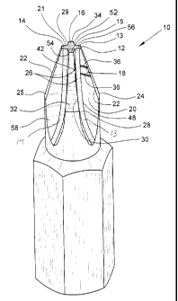
Referring now to figures 1-5, an anti-skip fastener tightening and/or
extraction device is
denoted by numeral 10. The device 10 includes a tool bit end 12 having a cross
configuration
when taking an end view, and formed from four substantially identical crossing
members 13, 14,
15 and 16 that are radially separated a substantially equal degree of arc
thereby configuring a
typical screwdriver bit for a standard cross or "Phillips" head fastener 17.
Crossing members 13
and 14 have at least one, but preferably a plurality of parallel recesses 18
disposed in first side
walls 20 and 21 such that an acute angle is formed (when taking a front
elevation view of the
device, see figure 2 ) between the recesses 18 and a mid-portion of an
inclined edge 22 of first
and second inclined walls 24 and 25 of members 13 and 14. Crossing members 15
and 16 have
at least one, but preferably a plurality of parallel recesses 26 disposed in
second side walls 28 and
29 such that an acute angle is formed (when taking a back elevation view of
the device, see
figure 4) between the recesses 26 and a mid-portion of an inclined edge 30 of
first and second
inclined walls 32 and 34 of the second crossing member 16.
The recesses 18 in first side walls 20 and 21 form edges 36 that engage and
grasp the
fastener 17 by "digging" into corresponding first side walls 38 and 40 of
fastener 17 to maintain
engagement between the tool bit end 12 and the fastener 17 when forcibly
rotating the fastener 17
to drive the fastener 17 into a work-piece (not shown). The recesses 26 in the
second side walls
28 and 29 form edges 42 that engage and grasp the fastener 17 by "digging"
into corresponding
second side walls 44 and 46 of fastener 17 to maintain engagement between the
tool bit end 12
and the fastener 17 when forcibly rotating the fastener 17 to extract the
fastener 17 from a
7
CA 02402959 2002-09-12
workpiece. The recesses 18 and 26 are relatively narrow and substantially
horizontal when
taking front or back elevation views. The recesses 18 in the first side walls
20 and 21 extend
across the first side walls 20 and 21 from an inner edge 48 to inclined edge
22 of corresponding
inclined walls 24 and 25. The recesses 26 in the second side walls 28 and 29
extend across the
second side walls 28 and 29 from an inner edge 48 to inclined edge 30 of
corresponding inclined
walls 32 and 34. The recesses 18 and 26 are separated a distance relatively
larger than their
lateral dimension and include a relatively shallow "depth" relative to the
thickness of the
crossing members 13-16 of the tool bit end 12.
The recesses 18 and 26 may be orientated perpendicular or parallel to the
central axis of
the tool bit and may be positioned at any portion of the first and second side
walls 20, 21, 28 and
29 depending upon the size of the fastener 17 and the corresponding "depth" of
the first and
second side walls 38, 40, 44 and 46 into the fastener 17. Generally, the
deeper the first and
second side walls of the fastener 17, the greater the longitudinal dimension
of the recesses 18 and
26 across the first and second side walls of the tool bit end 12. The
longitudinal dimension is
increased by angling the recesses 18 and 26 to a more vertical position
extending from the inner
edge 48 to inclined edges 22 and 30, respectively as depicted in figure 6.
Further, the recesses 18
and 26 may vary in quantity from one to a plurality of recesses depending upon
the desired
"griping" capability of the device 10 upon the fastener 17.
Although the figures depict only the first side walls 20 and 21 of crossing
members 13
and 14, and the second side walls 28 and 29 of crossing members 15 and 16
having recesses
therein, all eight side walls of the tool bit end 12 may include recesses to
improve the gripping
capability of the device 10. More specifically, second side walls 56 and 58 of
crossing members
8
CA 02402959 2002-09-12
13 and 14, respectively, and first side walls 54 and 52 of crossing members 15
and 16,
respectively, may include recesses configured and disposed substantially
identical to the recesses
18 and 26 in corresponding side walls. However, adding recesses in the tool
bit end 12 weakens
the metal forming the end 12 thereby reducing the amount of rotational force
that can be applied
to the device 10 without deforming the end 12. Positioning recesses in
opposing side walls of the
same crossing member such that bottom portions are directly opposite, further
reduces the
rotational force that may be applied. To minimize metal degradation, recesses
in opposing side
walls of a crossing member may be staggered whereby the quantity metal
separating opposing
lower portions of corresponding recesses is increased. Thus, keeping the
quantity of recesses to a
minimum while adding optimum gripping capability to the tool bit end 12 and/or
avoiding
recesses in opposite side walls of one of the crossing members 13-16 increases
the amount of
rotary force that may be imparted upon a fastener 17.
Alternatively, the tool bit end 12 may be designed to provide gripping
capability in only
one rotary direction. More specifically, the tool bit end 12 may be required
to grip the fastener
17 to assemble a workpiece thereby requiring the recesses to grip the fastener
17 for insertion
only. Recesses that are disposed to remove fasteners would not be included.
Should the tool bit
end 12 be required to only remove fasteners 17 from a workpiece, recesses that
grip the fasteners
17 for extraction would be machined in the tool bit end 12, recesses that
insert fasteners 17
would not be included.
In operation, a standard screwdriver bit 12 configured to insert or remove a
Phillips head
fastener 17 from a workpiece, is machined via techniques well known to those
of ordinary skill in
the art such that one or more recesses 18 are formed in the first side walls
20 and 21 of crossing
9
CA 02402959 2002-09-12
members 13 and 14 for gripping the first side walls 38 and 40 of the fastener
17 during the
extraction (counter-clockwise rotation) of the fastener 17 from a workpiece.
Alternatively, one
or more recesses 26 are machined in the second side walls 28 and 29 of
crossing members 15 and
16 for gripping the second side walls 44 and 46 of the fastener 17 during the
insertion (clockwise
rotation) of the fastener 17 into the workpiece. Should the bit 12 be required
to grip the fastener
17 for both extraction and insertion, recesses 18 and 26 would be machined in
corresponding first
and second side wall 20,21,28 and 29. Should a relatively small amount of
rotary force be
imparted upon the fastener 17 by the bit 12, and a relatively large gripping
capability be required
to insert and/or extract the fastener 17 from a workpiece, recesses 18 and/or
26 may be machined
in corresponding first side walls 20,21,52 and 54 and/or second side walls
28,29,56 and 58 of the
crossing members 13,14,15 and 16 (see figures 1 and 3).
Referring now to figure 7, a standard "blade" screwdriver tip 60 is depicted
having a
plurality of recesses 62 machined in first and second sides 64 and 66 of the
tip 60. The recesses
62 are parallel to the edge 68 of the tip 60, extend laterally across
substantially half the tip 60,
and include a "depth" relatively shallow in comparison to the "thickness" of
the tip 60 thereby
substantially maintaining the structural strength of the tip 60. The recesses
62 on each side 64
and 66 of the tip 60 are separated a distance relatively greater than the
lateral dimension of the
recesses 62. Machining recesses 62 across half the tip 60, maintains tip
integrity but provides
gripping capability in only one rotary direction. Extending the recesses 62
across the entire
surface of the tip 60 would enable the tip 60 to grip the fastener in both
rotary direction, but
would decrease the structural strength of the tip 60 thereby reducing the
amount of rotary force
that may be imparted upon the screwdriver. Further, the recesses 62 may be
inclined relative to
CA 02402959 2002-09-12
the edge 68 or may be increased in quantity to increase the gripping
capability of the tip 60, but
resulting in a corresponding decrease in structural strength and the amount of
rotational force that
may be imparted from the tip 60 to the fastener. Staggering or varying the
distances between the
recesses 62 of the first side wall 64 and the edge 68 of the tip 60 relative
to the distances between
the recesses 62 of the second side wall 66 and the edge 68 of the tip, avoids
"back-to-back"
placement of the recesses 62, thereby substantially maintaining the structural
integrity of the tip
60.
Referring now to figures 8 and 9, an alternative anti-skip fastener tightening
and/or
extraction device is denoted by numeral 100. The device 100 of figure 8 is
substantially the same
as the device 10 of figure 1 except that the recesses 18 and 26 in the
alternative device 100 have
been disposed closer to the tool bit end 12 to engage corresponding side walls
38, 40, 44 and 46
of a fastener 17 having relatively "shallow" recesses 102 that form the side
walls 38, 40, 44 and
46. The device 100 further includes arcuate crossing members 13-16 that
accommodate a slight
grease, dirt and/or metal filing "buildup" 103 in corners 104 of the recesses
102 in the fastener
IT Thus, the device 100 is allowed to insert into the fastener 17 until a
slightly crowned portion
106 of the device 100 engages a center portion 108 of the fastener 17, and the
arcuate crossing
members 13-16 engage and forcibly compress the grease and dirt buildup 103.
The arcuate
configuration facilitates total engagement and maximum "gripping" capability
between the recess
18 and 26 of the device 100 and the side walls of a fastener 17 with shallow
recesses 102 that
have a foreign material buildup therein.
The foregoing description is for purposes of illustration only and is not
intended to limit
the scope of protection accorded this invention. The scope of protection is
measured by the
following claims, which should be interpreted as broadly as the inventive
contribution permits.
11