Note: Descriptions are shown in the official language in which they were submitted.
CA 02402969 2002-09-16
WO 01/76770 PCT/US01/06424
ELECTROSTATICALLY ASSISTED COATING
METHOD AND APPARATUS WITH FOCUSED ELECTRODE FIELD
TECHNICAL FIELD
This invention relates to an electrostatically assisted coating method and
apparatus.
More specifically, the invention relates to using electrostatic fields at the
point of coating
fluid contact with a moving web to achieve improved coating process
uniformity.
BACKGROUND OF THE INVENTION
Coating is the process of replacing the gas contacting a substrate, usually a
solid
surface such as a web, by one or more layers of fluid. A web is a relatively
long flexible
substrate or sheet of material, such as a plastic film, paper or synthetic
paper, or a metal
foil, or discrete parts or sheets. The web can be a continuous belt. A coating
fluid is
functionally useful when applied to the surface of a substrate. Examples of
coating fluids
are liquids for forming photographic emulsion layers, release layers, priming
layers, base
layers, protective layers, lubricant layers, magnetic layers, adhesive layers,
decorative
layers, and coloring layers.
After deposition, a coating can remain a fluid such as in the application of
lubricating oil to metal in metal coil processing or the application of
chemical reactants to
activate or chemically transform a substrate surface. Alternatively, the
coating can be
dried if it contains a volatile fluid to leave behind a solid coat such as a
paint, or can be
cured or in some other way solidified to a functional coating such as a
release coating to
which a pressure-sensitive adhesive will not aggressively stick. Methods of
applying
coatings are discussed in Cohen, E.D. and Gutoff, E.B., Modern Coating and
Drying
Technology, VCH Publishers, New York 1992 and Satas, D., Web Processing and
Converting Technology and Equipment, Van Vorstrand Reinhold Publishing Co.,
New
York 1984.
The object in a precision coating application is typically to uniformly apply
a
coating fluid onto a substrate. In a web coating process, a moving web passes
a coating
CA 02402969 2002-09-16
WO 01/76770 PCT/USO1/06424
station where a layer or layers of coating fluid is deposited onto at least
one surface of the
web. Uniformity of coating fluid application onto the web is affected by many
factors,
including web speed, web surface characteristics, coating fluid viscosity,
coating fluid
surface tension, and thickness of coating fluid application onto the web.
Electrostatic coating applications have been used in the printing and
photographic
areas, where roll and slide coating dominate and lower viscosity conductive
fluids are
used. Although the electrostatic forces applied to the coating area can delay
the onset of
entrained air and result in the ability to run at higher web speeds, the
electrostatic field that
attracts the coating fluid to the web is fairly broad. One known method of
applying the
electrostatic fields employs precharging the web (applying charges to the web
before the
coating station). Another known method employs an energized support roll
beneath the
web at the coating station. Methods of precharging the web include corona wire
charging
and charged brushes. Methods of energizing a support roll include conductive
elevated
electrical potential rolls, nonconductive roll surfaces that are precharged,
and powered
semiconductive rolls. While these methods do deliver electrostatic charges to
the coating
area, they do not present a highly focused electrostatic field at the coater.
For example, for
curtain coating with a precharged web, the fluid is attracted to the web and
the equilibrium
position of the fluid/web contact line (wetting line) is determined by a
balance of forces.
The electrostatic field pulls the coating fluid to the web and pulls the
coating fluid upweb.
The motion of the web creates a force which tends to drag the wetting line
downweb.
Thus, when other process conditions remain constant, higher electrostatic
forces or lower
line speeds result in the wetting line being drawn upweb. Additionally, if
some flow
variation exists in the crossweb flow of the coating fluid, the lower flow
areas are
generally drawn further upweb, and the higher flow areas are generally drawn
further
downweb. These situations can result in decreased coating thickness
uniformity. Also,
process stability is less than desired because the fluid contact line (wetting
line) is not
stable but depends on a number of factors.
There are many patents that describe electrostatically-assisted coating. Some
deal
with the coating specifics, others with the charging specifics. The following
are some
representative patents. U.S. Patent No. 3,052,131 discloses coating an aqueous
dispersion
using either roll charging or web precharging, U.S. Patent No. 2,952,559
discloses slide
2
WU 01/76770 CA 02402969 2002-09-16 pCT/[JSO1/06424
coating emulsions with web precharging, and U.S. Patent No. 3,206,323
discloses viscous
fluid coating with web precharging.
U.S. Patent No. 4,837,045 teaches using a low surface energy undercoating
layer
for gelatins with a DC voltage on the backup roller. A coating fluid that can
be used with
this method include a gelatin, magnetic, lubricant, or adhesive layer of
either a water
soluble or organic nature. The coating method can include slide, roller bead,
spray,
extrusion, or curtain coating.
EP 390774 B 1 relates to high speed curtain coating of fluids at speeds of at
least
250 cm/sec (492 ftlmin), using a pre-applied electrostatic charge, and where
the ratio of
the magnitude of charge (volts) to speed (cm/sec) is at least 1:1.
U.S. Patent No. 5,609,923 discloses a method of curtain coating a moving
support
where the maximum practical coating speed is increased. Charge may be applied
before
the coating point or at the coating point by a backing roller. This patent
refers to
techniques for generating electrostatic voltage as being well known,
suggesting that it is
referring to the listed examples of a roll beneath the coating point or
previous patents
where corona charging occurs before coating. This patent also discloses corona
charging.
The disclosed technique is to transfer the charge to the web with a corona,
roll, or bristle
brush before the coating point to set up the electrostatic field on the web
before the coating
is added.
FIGS. 1 and 2 show known techniques for electrostatically assisting coating
applications. In FIG. 1, a web 20 moves longitudinally (in the direction of
arrows 22) past
a coating station 24. The web 20 has a first major side 26 and a second major
side 28. At
the coating station 24, a coating fluid applicator 30 laterally dispenses a
stream of coating
fluid 32 onto the first side 26 of the web 20. Accordingly, downstream from
the coating
station 24, the web 20 bears a coating 34 of the coating fluid 32.
In FIG. 1, an electrostatic coating assist for the coating process is provided
by
applying electrostatic charges to the first side 26 of the web 20 at a charge
application
station 36 spaced longitudinally upstream from the coating station 24 (the
charges could
alternatively be applied to the second side 28). At the charge application
station 36, a
laterally disposed corona discharge wire 38 applies positive (or negative)
electrical
charges 39 to the web 20. The wire 38 can be on either the first or second
side of the web
20. The coating fluid 32 is grounded (such as by grounding the coating fluid
applicator
3
WO 01/76770 CA 02402969 2002-09-16 pCT/[JSOi/06424
30), and is electrostatically attracted to the charged web 20 at the coating
station 24. A
laterally disposed air dam 40 can be disposed adjacent and upstream of the
coating station
24 to reduce web boundary layer air interference at the coating fluid web
interface 41.
The corona wire could be aligned in free space along the web (as shown in FIG.
1 ) or
alternatively, could be aligned adjacent the first side of the web while the
web is in contact
with a backing roll at the coating station.
FIG. 2 shows another known electrostatically assisted coating system. In this
arrangement, a relatively large diameter backing roll 42 supports the second
side 28 of the
web 20 at the coating station 24. The backing roll 42 can be a charged
dielectric roll, a
powered semiconductive roll, or a conductive roll. The conductive and
semiconductive
rolls can be charged by a high voltage power supply. With a dielectric roll,
the roll can be
provided with electrical charges by suitable means, such as a corona charging
assembly
43. Regardless of the type of backing roll 42 or its means of being charged,
its outer
cylindrical surface 44 is adapted to deliver the electrical charges 39 to the
second side 28
of the web 20. As shown in FIG. 2, the electrical charges 39 from the backing
roll 42 are
positive charges, and the coating fluid 32 is grounded by grounding the
coating fluid
applicator 30. Accordingly, the coating fluid 32 is electrostatically
attracted to charges
residing at the interface between the web 20 and the outer cylindrical surface
44 of the roll
42. The air dam 40 reduces web boundary layer air interference at the coating
fluid web
interface 41.
Known electrostatically assisted coating arrangements such as those shown in
FIGS. 1 and 2 assist the coating process by delaying the onset of air
entrainment and
improving the wetting characteristics at the coating wetting line. However,
they apply
charges to the web at a location substantially upstream from the wetting line,
and generate
fairly broad electrostatic fields. They are largely ineffective in maintaining
a straight
wetting line when there are crossweb coating flow variations or cross-web
electrostatic
field variations. For instance, in a curtain coater, if a localized heavy
coating fluid flow
area occurs somewhere across the curtain, the wetting line in this heavier
coating region
can move downweb in response depending on materials or process parameters.
This can
create an even heavier coating in this area due to stress and strain on the
curtain, especially
for fluids which exhibit elastic characteristics (more elastic fluids have
high extensional
viscosity in relation to shear). In addition, if the electrostatic field is
not uniform (e.g.,
4
CA 02402969 2002-09-16
WO 01/76770 PCT/USO1/06424
there is a corona web precharge non-uniformity), the lower voltage area on the
web will
allow the wetting line in that area to move downweb, thus increasing the
coating weight in
that area. These effects become increasingly dominant as fluid elasticities
increase. Thus,
crossweb fluid flow variations and crossweb electrostatic field variations
cause non-
uniformity in the wetting line and, as a result, the application of a non-
uniform coating on
the web.
None of the known apparatus or methods for electrostatically assisted coating
discloses a technique for applying a focused electrical field to the web at
the coating
station from an electrical field applicator to improve the characteristic of
the applied fluid
coating and also to attain improved processing conditions. There is a need for
an
electrostatically assisted coating technique that applies a more focused
electrical field to
the web at the coating station.
SUMMARY OF THE INVENTION
The invention is a method of applying a fluid coating onto a substrate. The
substrate has a first surface on the first side thereof and a second surface
on a second side
thereof. The method includes providing relative longitudinal movement between
the
substrate and a fluid coating station, and forming a fluid wetting line by
introducing, at an
angle of from 0 degrees through 180 degrees, a stream of fluid onto the first
side of the
substrate along a laterally disposed fluid-web contact area at the coating
station. An
electrical force is created on the fluid from an effective electrical field
originating from a
location on the second side of the substrate that is substantially at and
downstream of the
fluid wetting line, without requiring electrical charges to move to the
substrate while
attracting the fluid to the first surface of the substrate via electrical
forces.
The creating step can include electrically energizing an electrode on the
second
side of the substrate to form the effective electrical field from electrical
charges. In one
embodiment, the effective electrical field is defined by a portion of the
electrode which
has a radius of no more than 1.27 cm (or, in one preferred embodiment, no more
than 0.63
cm).
The substrate can be supported, adjacent the fluid coating station, on the
second
side thereof, or can be supported by the electrode itself.
5
WO 01/76770 CA 02402969 2002-09-16 pCT/US01/06424
The stream of fluid can be formed with a coating fluid dispenser such as a
curtain
coater, a bead coater, an extrusion coater, carrier fluid coating methods, a
slide coater, a
knife coater, a jet coater, a notch bar, a roll coater or a fluid bearing
coater. The stream of
coating fluid can be tangentially introduced onto the first surface of the
substrate.
The electrical charges of the electrode can have a first polarity and second
electrical charges (having a second, opposite polarity) can be applied to the
stream of fluid
before the stream of fluid is introduced onto the substrate.
The creating step can include electrically energizing an electrode and also
acoustically exciting the electrode. In one preferred embodiment, the
electrode is
acoustically excited at ultrasonic frequencies.
The inventive method is also defined as a method of applying a fluid coating
onto a
substrate, where the substrate has a first side and a second side. The
inventive method
includes providing relative longitudinal movement between the substrate and a
fluid
coating station. A stream of fluid is introduced, at an angle of 0 degrees
through 180
degrees, onto the first side of the substrate to form a fluid wetting line
along a laterally
disposed fluid-web contact area at the coating station. The invention further
includes
attracting the fluid to the first side of the substrate at a location on the
substrate that is
substantially at and downstream of the fluid wetting line by electrical forces
from an
effective electrical field originating at a location on the second side of the
substrate.
The invention is also an apparatus for applying a coating fluid onto a
substrate
which has a first surface on a first side thereof and a second surface on a
second side
thereof. The apparatus includes means for dispensing a stream of coating fluid
onto the
first surface of the substrate to form a fluid wetting line along a laterally
disposed fluid
contact area. A field applicator extending laterally across the second side of
the substrate
(generally opposite the fluid wetting line) bears electrical charges, and
applies an effective
electrical field to the substrate at a location on the substrate that is
substantially at and
downstream of the fluid wetting line to attract the fluid to the first surface
of the substrate.
The effective electrostatic field primarily emanates from electrical charges
on the
electrical field applicator rather than electrical charges transferred to the
substrate.
The electrical field applicator can include a small diameter rod, a conductive
strip,
or a conductive member with a small radius portion for use in defining the
effective
electrical field. An air bearing can extend laterally across the substrate
adjacent the
6
CA 02402969 2002-09-16
WO 01/76770 PCT/USO1/06424
electrical field applicator for supporting and aligning the second side of the
substrate
relative to the electrical field applicator.
In another embodiment, the invention is defined as a method of applying a
fluid
coating onto a substrate which has a first surface on a first side thereof and
a second
surface of a second side thereof. The method includes providing relative
longitudinal
movement between the substrate and a fluid coating station, forming a fluid
wetting line
by introducing, at an angle of 0 degrees through 180 degrees, a stream of
fluid onto the
first surface of the substrate along a laterally disposed fluid-web contact
area at the coating
station, exposing the coating fluid (adjacent the coating station) to an
electrical force to
attract the fluid to the substrate, and exposing the coating fluid (adjacent
the coating
station) to an acoustical force to attract the coating fluid to the substrate.
In another embodiment, the invention is an apparatus for applying a coating
fluid
onto a substrate having relative longitudinal movement with respect to the
apparatus. The
substrate has a first surface on the first side thereof and a second surface
on the second
side thereof. A coating fluid applicator dispenses a stream of coating fluid
onto the first
surface of the substrate to form a fluid wetting line along a laterally
disposed fluid contact
area. An electrical field applicator applies an electrostatic field at a
location on the
substrate adjacent the fluid wetting line to attract the coating fluid to the
first surface of the
substrate. An acoustical field applicator applies an acoustical field at a
location on the
substrate adjacent the fluid wetting line to attract the coating fluid to the
first surface of the
substrate.
BRIEF DESCRIPTION OF THE DRAWINGS
FIG. 1 is a schematic view of a known electrostatic coating apparatus where
charges are applied to the moving web before it enters a coating station from
an upweb
corona wire.
FIG. 2 is a schematic view of a known electrostatic coating apparatus where
charges are delivered to the moving web from a backing roll under the moving
web at the
coating station.
FIG. 3 is a schematic view of one embodiment of the electrostatically assisted
coating apparatus of the present invention where the effective electrostatic
field is defined
7
CA 02402969 2002-09-16
WO 01/76770 PCT/USO1/06424
by a lateral electrode adjacent the coating fluid wetting line in combination
with an air
bearing assembly.
FIG. 4 is an enlarged view of the air bearing assembly with the electrode of
FIG. 3.
FIG. 5 is an enlarged schematic view of a portion of FIG. 2 illustrating the
applied
electrostatic charges and lines of force.
FIG. 6 is an enlarged schematic view of a portion of FIG. 3 illustrating the
electrostatic lines of force of the effective electrical field.
FIG. 7 is a schematic view of another embodiment of the electrostatically
assisted
coating apparatus of the present invention, illustrating one application of
its use for
tangential curtain coating.
FIG. 8 is an enlarged schematic illustration of an air bearing and
electrostatic field
generation system with multiple electrodes.
FIG. 9 is a schematic view of a tangential coating test arrangement with a
prior art
sized powered roll.
FIG. 10 is a schematic view of another embodiment of the electrostatically
assisted
coating apparatus of the present invention, in a generally tangential coating
configuration.
FIG. 11 is an enlarged schematic illustration of the electrode assembly of
FIG. 10.
FIG. 12 is a schematic view of another embodiment of the electrostatically
assisted
coating apparatus of the present invention, where the effective electrostatic
field is defined
by a one-inch diameter backing roll.
FIG. 13 is a schematic view of an inventive electrostatic field electrode
which is
combined with an ultrasonic horn.
FIG. 14 illustrates the "dynamic contact angle" of fluid coating onto a web.
While some of the above-identified drawing figures set forth preferred
embodiments of the invention, other embodiments are also contemplated, as
noted in the
discussion. In all cases, this disclosure presents the invention by way of
representation
and not limitation. It should be understood that numerous other modifications
and
embodiments can be devised by those skilled in the art, which fall within the
scope and
spirit of the principles of the invention.
8
WO 01/76770 CA 02402969 2002-09-16 pCT/USO1/06424
DETAILED DESCRIPTION OF PREFERRED EMBODIMENTS
This invention includes an apparatus and coating method which use more focused
electrostatic fields at the interface between a substrate (such as a web) to
be coated and a
fluid coating material applied on the substrate. The inventors have found that
more
focused electrostatic fields can improve the coating process by stabilizing,
straightening,
and dictating the position of the coating wetting line, allowing wider process
windows to
be achieved. For example, the invention makes possible a wider range of
coating weights,
coating speeds, coating geometries, web features such as dielectric strengths,
coating fluid
characteristics such as viscosity, surface tension, and elasticity, and die-to-
web gaps, as
well as improving cross web coating uniformity. With curtain coating,
electrostatic
coating assist allows lower curtain heights (and therefore, greater curtain
stability) and
allows the coating of elastic solutions which could not previously be coated
without
entrained air. Focused fields greatly enhance the ability to run coating
fluids (especially
elastic fluids) since they more precisely dictate the position, linearity, and
stability of the
wetting line, which results in increased process stability. In addition,
thinner coatings than
were previously possible can be produced, even at lower line speeds, which is
important
for processes that are drying or curing rate limited.
With extrusion coating it has been found that electrostatics permits the use
of lower
elasticity waterbased fluids (such as some waterbased emulsion adhesives) that
cannot be
extrusion coated absent the electrostatics (in the extrusion mode), as well as
permitting the
use of larger coating gaps.
In curtain coating, the stream of fluid is aligned with the gravitational
vector, while
in extrusion coating it can be aligned with the gravitational vector or at
other angles.
While coating with a curtain coating process, where longer streams of fluid
are used, the
coating step involves the displacing of the boundary layer air with coating
fluid and the
major force is momentum based. In contrast, with extrusion coating, where the
stream of
fluid is typically shorter than for curtain coating, the major forces are
elasticity and surface
tension related. When using electrostatics an additional force results which
can assist in
displacing the boundary layer air, or can become the dominant force itself.
Although the invention is described with respect to smooth, continuous
coatings,
the invention also can be used while applying discontinuous coatings. For
example,
electrostatics can be used to help coat a substrate having a macrostructure
such as voids
9
CA 02402969 2002-09-16
WO 01/76770 PCT/US01/06424
which are filled with the coating, whether or not there is continuity between
the coating in
adjacent voids. In this situation, the coating uniformity and enhanced
wettability
tendencies are maintained both within discrete coating regions, and from
region to region.
The substrate can be any surface of any material that is desired to be coated,
including a web. A web can be any sheet-like material such as polyester,
polypropylene,
paper, knit, woven or nonwoven materials. The improved wettability of the
coating is
particularly useful in rough textured or porous webs, regardless of whether
the pores are
microscopic or macroscopic. Although the illustrated examples show a web
moving past a
stationary coating applicator, the web can be stationary while the coating
applicator
moves, or both the web and coating applicator can move relative to a fixed
point.
Generically speaking, the invention relates to a method of applying a fluid
coating
onto a substrate such as a web and includes providing relative longitudinal
movement
between the web and a fluid coating station. A stream of coating fluid is
introduced onto
the first side of the web along a laterally disposed fluid wetting line at a
coating station.
The coating fluid is introduced at any angle of from 0 degrees through 180
degrees. An
electrical force is created on the fluid from an effective electrical field
substantially at and
downstream of the fluid contact area (e.g., originating from one or more
electrodes that are
located on the second side of the web). Negative or positive electrical
charges may be used
to attract the coating fluid. The coating fluid can include solvent-based
fluids,
thermoplastic fluid melts, emulsions, dispersions, miscible and immiscible
fluid mixtures,
inorganic fluids, and 100% solid fluids. Solvent-based coating fluids include
solvents that
are waterbased and also organic in nature. Certain safety precautions must be
taken when
dealing with volatile solvents, for example that are flammable, because static
discharges
can create hazards, such as fires or explosions. Such precautions are known,
and could
include using an inert atmosphere in the region where static discharges might
occur.
Instead of precharging the web or using an energized roll support system, as
are
known, the preferred embodiments of the invention use an electrical field
source, such as
narrow conductive electrode extending linearly in the cross-web direction,
positioned
where the fluid web contact line should occur. The narrow conductive electrode
could be,
for example, a small diameter rod in the range of about 0.16 - 2.54 cm (0.06-
1.0 in), either
rotating or non-rotating, a narrow conductive strip, a member with a sharply
defined
(small radius portion) leading edge (the wetting line will typically be
located near the
CA 02402969 2002-09-16
WO 01/76770 PCT/USO1/06424
sharply defined leading edge), or any electrode with a geometry that presents
a focused
and effective electrical field to the wetting line that is substantially at
and downstream of
the wetting line. Generally, the smaller the radius, the more focused the
field. However if
the radius becomes too small, increased corona generation can occur. Rod
diameters less
than 0.16 cm (0.06 in) can be used as long as the applied voltage is not high
enough to
create significant corona discharge. If the discharge is too high, the
predominant electrical
force can come from corona charges that are deposited on the second surface of
the web.
The electrode can be supported by a small support structure such as a porous
air bearing
material adjacent the electrode on the upweb and downweb sides. The web can be
supported by the air bearing surface, or by the electrode itself. The
electrode can be
closely spaced from the web or can be in physical contact with the web. The
electrode can
also have discrete, discontinuous crossweb support structures, or can be
supported only on
its ends. The electrode can also be made of a porous conductive material.
The main attractive force for this embodiment comes from the electrostatic
field
originating from the electrode, not from charges transferred to the backside
of the web by
contact or spurious corona discharge. Again, the field is focused to be
effective (as an
attractant for the coating fluid) substantially at or downstream of the web-
fluid contact
line. The electrode on the backside of the web creates a more focused
electrical field than
known electrostatic coating assist systems. Because the field does not extend
as far upweb
as in the prior art (precharged webs or energized coating rolls), the fluid is
drawn to a
more sharply defined wetting line, retains a more linear crossweb profile, and
stabilizes
the wetting line by tending to lock it into position. This means that the
normal balance of
forces that dictate the contact line position are less important, and that non-
linearities in
the wetting line are less pronounced. Thus, process variations, such as
coating flow rates,
coating crossweb uniformity, web speed variations, incoming web charge
variations, and
other process variations have less effect on the coating process. Typically
the smaller the
diameter of the electrode or the more sharply defined the leading edge of the
electrode
structure, the more focused the leading edge of the electrostatic field and
wetting line
linearity will become, as long as spurious corona discharges can be kept to a
minimum.
Process stability is greatly enhanced with the focused electrode field system.
Typically, if an electrostatically assisted coating system is running at a
particular speed,
coating thickness, and voltage, changing one of these variables changes the
wetting line
11
WO 01/76770 CA 02402969 2002-09-16 PCT/USO1/06424
position. For example, the wetting line will shift downweb if speed is
increased, coating
thickness is increased, or applied voltage is decreased, depending on the type
of coating
system and fluid being coated. This can cause coating uniformity problems and
can
increase the potential for air entrainment. The inventive focused field system
greatly
reduces the sensitivity of the process to those variables and maintains the
wetting line at a
more stable straight line position.
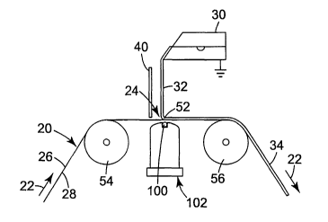
Many configurations of the electrode can be used in practicing the invention.
FIG.
3 shows an example where a laterally extending electrode 100 is supported
along the
second side 28 of the web 20. The laterally extending electrode 100 is
uniformly and
closely spaced from or may be contacting the second side 28 of the web 20,
longitudinally
close to the coating station 24 that includes the lateral coating fluid web
contact line 52.
The web 20 is supported at the coating station 24 such as between a pair of
support rolls
54, 56. Alternatively, the web 20 can be supported at the coating station 24
by the
electrode itself, an air bearing 102 (or any suitable gas bearing, such as an
inert gas
bearing), or other supports. A stream of coating fluid 32 is delivered from
the coating
fluid applicator 30 onto a first surface on the first side 26 of the web 20.
As shown, the
coating fluid applicator 30 can be grounded to ground the coating fluid 32
relative to the
electrode 100. The air dam 40 can be any suitable physical barrier which
limits boundary
layer air interference at the coating fluid web interface or the point of
coating curtain
formation.
The electrode 100 may be formed, for example, from a small diameter rod or
other
small dimension conductive electrode (which does not necessarily need to be
round).
Preferably, the electrode 100 is disposed within the adjacent air bearing 102,
which may or
may not be in contact with the air bearing. The air bearing 102 stabilizes the
web position
and minimizes the web vibrations which otherwise can have an adverse effect on
coating
stability and uniformity. The air bearing 102 is typically radiused and
preferably has a
porous material 104 (such as porous polyethylene) in fluid communication with
an air
manifold chamber 106. Pressurized air is provided to the air manifold chamber
106 via
one or more suitable inlets 108, as indicated by arrow 110. The air flows
through the air
manifold chamber 106 and into the porous membrane 104. The porous membrane 104
has
a relatively smooth and generally radiused bearing surface 112 positioned
adjacent a
second surface of the web 20 on the second side 28 thereof. Air exiting the
bearing
12
WO 01/76770 CA 02402969 2002-09-16 pCT/USO1/06424
surface 112 supports the web 20 as it traverses the coating station 24 and
electrode 100.
While an active air bearing is described, a passive air bearing (using only
the air boundary
layer on the second side of the web as the bearing media) can work at
sufficiently high
web speeds. The air bearing can also be a solid structure that acts as an air
bearing as
substrate speeds increase and boundary layer air on the second side of the web
creates the
air bearing effect. The gap between the air bearing surface and web is a
function of
parameters such as the radius of the air bearing, the web tension and speed of
the web.
Other known ways of creating an air bearing can also be used such as airfoil
designs
commonly used in drying.
The embodiment of the electrostatic coating assist system of FIG. 3 forms a
more
focused electrostatic field at the fluid-web contact area which constrains the
wetting line to
a more linear profile at a desired location. The embodiment "locks" the
wetting line into a
stable line extending laterally across the web (as compared to the less
effective known
electrostatic coating assist systems of FIGS. 1 and 2 which provide a less
focused
electrostatic attraction between the coating fluid and web). The electrostatic
field
emanating from the electrode creates the main electrostatic attractive (i.e.,
effective) force
on the coating fluid. Electrostatic charges are not placed primarily from the
electrode onto
the web itself. Rather, their presence on the charged device, such as an
elevated potential
electrode, attracts the coating fluid. It is intended that charges not be
transferred to be the
web from the electrode, although in practice, some inevitably will transfer
and assist in the
coating process.
Instead of grounding the coating fluid 32, an opposite electrical charge can
be
applied to the coating fluid 32 such as by a suitable electrode device. In
addition, the
applied polarities of the electrical charges to the coating fluid 32 and web
20 can be
reversed. This method is particularly useful when using lower electrical
conductivity
fluids such as certain 100% polymer melts or 100% solids curable systems. For
example,
for a low conductivity fluid, charges can be applied to the fluid before
coating, whether
through the die or by a corona discharge. This system can be used when
insufficient
electrostatic aggressiveness is seen due to the use of low conductivity
fluids. The ability of
the inventive system to retain the fluid wetting line in a more linear fashion
results in
increased coating uniformity and stability. For a conductive fluid where the
conductive
path is isolated, the die potential can be raised to create the opposite
polarity in the fluid.
13
CA 02402969 2002-09-16
WO 01/76770 PCT/USO1/06424
Alternatively, the opposite polarity can be applied to the fluid anywhere
along the
conductive, isolated path (including, for example, even downstream of the
wetting line).
FIG. 5 is an expanded view of the prior art system in FIG. 2, and lines of
force 66
generated by the electrostatic charges relative to the coating fluid 32. For
curtain coating
applications, the desired wetting line is typically the gravity-determined
coating fluid
wetting line (with no electrostatics applied) when the web is stationary (or
initial coating
fluid wetting line (with no electrostatics applied) when the web is
stationary) and, as
illustrated in FIGS. 2 and 5, is the top dead center of the charged roll.
However, other
wetting line positions are common and depend on the type of coating die, fluid
properties,
and web path. The lines of force 66 indicate that for a charged roll (like the
roll 42 in FIG.
2) the forces are not well focused and the charges are exerting forces on the
coating fluid
substantially upweb of the wetting line (e.g., on upweb area 67). For example,
for charged
rolls that are larger than 7.5 cm (3 in) in diameter, the charges exert forces
on the coating
fluid substantially upweb from the desired wetting line. However, as the
delivery of
charges to the web becomes more focused, say for a one-inch diameter roll
given the same
potential, the charges do not exert functional forces on the coating fluid
substantially
upweb from the desired wetting line that adversely affect the wetting line
uniformity (i.e.,
the charges on the web are ineffective upweb relative to the coating fluid).
FIG. 6 is an expanded view of the inventive system of FIG. 3, showing where
the
electrical field is effective as an attractant for the coating fluid, as it is
more focused
beneath the coating fluid contact line. In this case, the lines of force 69
are more focused,
thus creating a more sharply defined and linear wetting line which stabilizes
the fluid-web
contact line by tending to lock it into position across the web travel path.
In an inventive electrostatic coating assist system such as illustrated in
FIG. 3, the
electrode 100 can be positioned directly under the laterally extending coating
fluid-web
contact line, which is determined by the placement (such as by gravitational
fall) of the
coating fluid 32 onto the web 20. Web movement, surface tension, and boundary
layer
effects on the first side of the web 20, and the elasticity of the coating
fluid 32, can cause
the coating fluid web contact line to shift downweb. Because of the strong
electrostatic
attraction that can be achieved with this invention, the location of the
electrode 100 will
determine the operational location of the wetting line when the electrode 100
is activated.
Thus, the location of the electrode 100 (upstream or downstream from the
initial coating
14
W0 01/76770 CA 02402969 2002-09-16 PCT/USO1/06424
fluid-web contact line) can cause a corresponding movement of the contact
line, as it tends
to align itself with the opposed attracted electrical charges. Preferably, the
electrode 100
is positioned no more than 2.54 cm ( 1.0 in) upstream or downstream from the
initial
coating fluid-web contact line.
As mentioned above, the electrode may take many forms, but it is essential
that it
create an effective electrical field for highly focused attraction of the
coating fluid to a
desired wetting line location. This may be accomplished by forming portions of
the
electrode with certain specific geometries. For example, a leading edge or an
edge
adjacent the web may be formed to have a specifically tuned radius for
creating the desired
electrical force field lines. In this instance, that portion of the electrode
preferably has a
radius of no greater than 1.27 cm (0.5 in), and more preferably a radius of no
greater than
0.63 cm (0.25 in). Other field focusing means are also possible. For instance,
an
additional electrode could be located adjacent the first electrode so as to
modify the field
from the first electrode. The second electrode may be positioned at any
location, including
upstream from the first electrode 100 or even on the first side 26 of the web
20, so long as
its resultant electrostatic field has the desired focusing effect on the
electrostatic field
generated from the first electrode 100. The result of focusing the
electrostatic field
generated by the electrode 100 is a straighter wetting line which is less
sensitive to non-
uniform fluid flow or charge variations of the electrode or on the incoming
web, thereby
providing a more uniform coating and greater process tolerance to production
variations.
It will be understood that the location of the electrode can be upstream or
downstream of the fluid wetting line so long as the effective electrical field
is substantially
at or downstream of the fluid wetting line. For example, an electrode can be
configured so
that surface charge density is higher substantially at or downstream of the
fluid wetting
line to focus the effective electrical field substantially at or downstream of
the fluid
wetting line. Alternatively, the effective electrical field can be focused
substantially at or
downstream of the fluid wetting line by masking the upstream electrical field
with a
conductive or nonconductive shield or grounding plate, for example, as
described in US
patent application Serial No. , filed April 6, 2000, on Electrostatically
Assisted
Coating Method And Apparatus With Focused Web Charge Field, by John W. Louks,
Nancy J. Hiebert, Luther E. Erickson and Peter T. Benson (Attorney Docket No.
51113USA4A).
CA 02402969 2002-09-16
WO 01/76770 PCT/USO1/06424
The use of a sharply defined electrode structure adjacent the wetting line to
create
an effective electrical field relative to the coating fluid also lends itself
well to tangential
fluid coating, especially with more elastic fluids. A tangential coating
apparatus using
such an electrode is shown in FIG. 7 (using an air bearing/electrode assembly
such as
illustrated in FIG. 4). Tangential curtain coating is generally capable of
running coating
fluids with higher extensional viscosities than is possible with horizontal
curtain coating
geometries. A tangential coating geometry also offers advantages associated
with the
handling of the coating fluid in the coating process. For example, if a web
break occurs in
the coating system illustrated in FIG. 3, the electrode can become coated with
coating
fluid, which will result in downtime for coater cleanup. In addition, if the
coating die is to
be purged before start-up, a catch pan geometry must be present which can
complicate the
coating station structure. Another advantage from tangential coating is that
curtain edge
bead control during coating is more easily achieved due to the removal of
space
constraints between the bottom of the die or coating fluid applicator 30 and
the web
support structure (e.g., the air bearing 102).
FIG. 8 illustrates another embodiment of the air bearing assembly shown in
FIG. 7.
For a particular fluid an optimum curtain length exists for a particular web
speed range. In
general, higher speeds or higher coat weights can require longer curtains and
lower speeds
or lower coat weights can require shorter curtains. While in FIG. 7 only one
electrode is
shown, the multiple electrode assembly shown in FIG. 8 has the advantage of
allowing the
operator to change the curtain height by energizing the appropriate electrode.
For
example, a shorter curtain could be used for a thin coating or lower web
speeds, while a
longer curtain could be used for higher line speeds. Thus rather than moving
the die down
to define a shorter curtain length, the electrode I OOa closest to the die 30
can be energized,
and rather than moving the die up to define a longer curtain length, the
electrode 100b
farthest from the die 30 can be energized. The spacings of the electrodes can
be selected
depending on the fluid characteristics and speed ranges desired.
In all embodiments of the present invention, an effective electrical field of
positive
electrical charges may be exposed to the web at the coating station, while
grounding the
coating fluid. In addition, a negative polarity may be applied to the coating
fluid.
Further, it is possible to reverse the polar orientations of the electrical
field and the charges
applied to the coating fluid. For instance, FIG. 8 illustrates a laterally
extending electrode
16
CA 02402969 2002-09-16
WO 01/76770 PCT/USOI/06424
120 (such as a corona wire) which is aligned to apply a positive charge to the
coating fluid
32. The electrode 120 may be shielded by one or more suitable laterally
extending shields
122 to direct and focus its application of positive charges 124 to the coating
fluid 32. In
that instance, the electrode 100 on the second side 28 of the web 20 has a
negative charge
relative to the web 20 traversed thereby, in order to create the desired
electrostatic
attraction effect. The shields 122 can be formed from a nonconductive or
insulating
material, such as DelrinT"' acetal resin made by E. I du Pont de Nemours of
Wilmington
Delaware or from a semiconductive or conductive material held at ground
potential or an
elevated potential. The shields 122 can formed in any shape to achieve the
desired
electrical shielding.
The utility of using focused fields at the fluid wetting line to achieve a
more linear
and stable wetting line was demonstrated in a series of experiments comparing
tangential
coating with a relatively large diameter charged roll (see, e.g., FIG. 9)
versus an
experimental focused electrode assembly (see, e.g., FIG. 10). The coating
fluid was a
100% solids curable fluid having a viscosity of approximately 3,000
centipoise. A curtain
length of approximately 4.45 cm ( 1.75 inches) was used (the curtain length
being
measured as the distance from the bottom of the die lip to the fluid contact
line). A curtain
charging corona wire was used and was about 3.18 cm ( 1.25 inches) vertically
below the
die lip and about 7.62 cm (3.0 inches) horizontally from the falling curtain.
The curtain
flow rate was adjusted to give a 50 micron (0.002 inch) coating thickness at a
web speed
of 91.4 m/min (300 ft/min). The charged roll system (FIG. 9) was a 11.3 cm
(4.55 inch)
diameter roll 126 with a 0.51 cm (0.2 inch) ceramic sleeve. The ceramic
surface was
charged by a corona wire system. The inventive focused electrode assembly (as
illustrated
in FIG. 11 ) included a nonconductive bar 128 with a 3.18 cm ( 1.25 inch)
radius surface. A
conductive foil 130 was adhered to the bar 128 with a leading edge 132 of the
conductive
foil 130 being about 0.25 cm (0.1 inches) above the tangent point on the bar
(the tangent
point being that point where the coating curtain, unaided by electrostatics,
would engage
the web passing over the bar 128). A nonconductive tape 131 has an edge
abutting the
leading edge 132 of the conductive foil 130. The focused field is created by
the leading
edge 132 of the foil 130. The foil 130 was charged using a negative polarity
high voltage
power supply. Positive and negative polarity Glassman series EH high voltage
power
17
WO 01/76770 CA 02402969 2002-09-16 pCT/USO1/06424
supplies manufactured by Glassman High Voltage, Inc. of Whitehouse Station,
New
Jersey were used for these experiments.
Using the charged roll system illustrated in FIG. 9, the curtain charging
corona
wire 120 was set at a negative 20 kilovolts and the roll 126 corona charger
set at a positive
20 kilovolts. The wetting line typically occurred about 1.27 cm (0.5 inches)
upweb of the
tangent point on the roll created by a vertical line from the die lip to the
roll (upweb from
point 134, FIG. 9). With a web speed of 76 m/min (250 ft/min) the wetting line
was wavy
with a total upweb-to-downweb deviation of 1.27 cm (0.5 inches). The measured
coating
thickness variation related to this was about 17.9 microns (0.0007 inches).
Increasing the
speed to 91.4 m/min (300 ft/min) resulted in entrained air in the coating 34.
Using the focused field system, major improvements were seen in wetting line
uniformity and coating uniformity. The electrode assembly of FIGS. 10 and 11
was
oriented in a tangential fashion similar to that shown in FIG. 7, but with the
incoming web
at a more acute angle. The curtain charging corona wire 120 was set at a
positive 20
kilovolts and the conductive foil 130 was set at a negative 20 kilovolts. At
91.4 m/min
(300 ft/min), excellent wetting line linearity was observed with a related
measured coating
variation of about 3.6 microns (0.00014 inches). These experiments demonstrate
the
improvements in wetting line linearity and coating thickness uniformity with
more focused
electrostatic fields.
Two tests with the focused field setup of FIGS. 10 and 11 were performed to
analyze the process sensitivity to the coating fluid input flow rate and
current charging
uniformity, running with a 50 micron (0.002 inch) coating thickness at a web
speed of
91.4 m/min (300 ft/min). First, a lateral segment of about 0.25 cm (0.1 in)
was blocked in
the slot of the coating fluid applicator 30 to create a lateral low flow rate
area in the
coating curtain 32. Second, a lateral section 0.33 cm (0.13 in) long of the
curtain charging
wire (electrode 120) was covered in another area, creating a lateral area of
reduced charge
on the coating curtain 32. With the focused field system of bar 128 activated,
no visual
deflection of the coating fluid/web contact line was observed by either of the
contrived
lateral discontinuities. Absent the focused field, the curtain 32 in the low
flow area would
bow upweb and the curtain 32 in the low charge area would bow downweb, with
both
conditions accentuating coating non-uniformities. Accordingly, the use of the
electrostatic
18
CA 02402969 2002-09-16
WO 01/76770 PCT/USOi/06424
focused field to facilitate coating is very effective in overcoming system
irregularities in
the coating fluid curtain.
Comparative quantitative analysis tests were also conducted to evaluate the
utility
of precharging the incoming fluid to increase the aggressiveness of the
electrostatic system
for fluids with limited electrical conductivity. In this series of tests, a
100% solids curable
fluid was coated on a 0.0036 cm (0.0014 inch) polyester web. The viscosity of
the fluid
was approximately 1,400 centipoise. A slide curtain die set up was used such
as illustrated
in FIG. 12, with a conductive backing roll 200 of only 2.54 cm ( 1.0 inch)
diameter,
attached to a positive polarity high voltage power supply. The die 30 was
located directly
above the top dead center of the roll 200, at a height of about 2.7 cm ( 1.06
inches).
However, it was observed that the aggressiveness of the coating method was
limited by the
low electrical conductivity of the coating fluid 32. To address this, the
surface of the
coating fluid 32 was charged to an opposite polarity of the energized backing
roll 200.
Two methods of doing this were investigated and seen to be functional, one
being to
elevate the potential of the die 30, and the other being the use of a corona
wire 220 (and
associated shield 222) to charge the surface of the fluid. The curtain
charging was
accomplished with a 0.015 cm (0.006 inch) diameter tungsten corona wire
located about
6.35 cm (2.5 inches) from the falling curtain on the downweb side of the
wetting line,
about 1.27 cm (0.5 inches) above the roll surface. The exact location of this
corona wire
220 was not extremely critical, and it could be located at different locations
along the
falling curtain, on the opposite side of the curtain, or adjacent the slide
surface of the die
30.
This series of tests was run on the inventive electrostatic coating assist
system of
FIG. 12 to determine the maximum coating speed that could be attained at a
given curtain
flow rate (a) without electrostatics, (b) with only the roll potential
elevated, and (c) with
the roll potential elevated along with curtain precharging. The flow rate of
the coating
fluid 32 was held constant and set to yield a dry coating thickness of 14.3
microns
(0.00057 inches) at 91.4 m/min (300 ft/min). With no electrostatics, the
wetting line
occurred 1.27 cm (0.5 inches) downweb of the top dead center of the roll 200
at a web
speed of 3.1 m/min ( 10 ft/min). At higher web speeds, the wetting line
deflected further
downweb, creating a bowed contact line, coating nonuniformity, air entrainment
and
curtain breakage. With the backing roll 200 energized to a positive 20
kilovolts, the
19
WO 01/76770 CA 02402969 2002-09-16 pC'T/[JSOl/06424
wetting line occurred at about 0. 64 cm (0.25 inches) downweb, at a web speed
of 24.4
m/min (80 ft/min). Further increases in speed resulted in the wetting line
moving further
downweb. With the roll 200 energized to a positive 20 kilovolts and the
curtain corona
charging wire 220 at a negative 11 kilovolts, the wetting line occurred at
about 0.64 cm
(0.25 inches) downweb at a web speed of 97.5 m/min (320 ft/min). These tests
show the
utility of charging lower conductivity coating fluids as a way to improve the
electrostatic
charge attraction aggressiveness of the inventive electrostatic coating assist
system.
Another set of experiments was conducted on the electrostatic coating assist
system of
FIG. 12 (using the same coating fluid) for the purpose of determining the
minimum
coating thickness that could be achieved at a web speed of 91.4 m/min (300
ft/min). With
no electrostatics (i.e., no charges applied to roll 200 or electrode 220) the
pumping system
used was not capable of supplying sufficient coating fluid 32 to get up to the
minimum
flow rate necessary to cause the wetting line to occur at the top dead center
position of the
roll 200 (the flow rate was not high enough to create the fluid momentum
necessary to
cause the wetting line to occur near the top dead center of the roll 200 and
the curtain to
maintain a vertical position). At this pump rate, which was less than the
minimum coating
thickness, the wetting line occurred about one inch downweb of the top dead
center
position of the roll 200, yielding a coating thickness of 85 microns (0.0034
inches).
Using electrostatics, with both the backing roll 200 and corona wire 220
energized as in
the previous example much thinner coatings were possible, with a minimum
coating
thickness of 6.5 microns (0.00026 inches) being achieved with the wetting line
occurring
essentially at the top dead center position of the roll 200.
Since it was observed that more focused electrostatic fields produced more
linear
and stable coating fluid wetting lines, a tangential coating system utilizing
a focused field
apparatus, similar to that shown in FIG. 7 was evaluated. The electrode 100 in
the air
bearing assembly 102 was a 0.157 cm (0.062 inch) diameter rod. For the first
experiment
with this design, a 100% solids curable fluid having a viscosity of
approximately 3,700
centipoise was use as a coating fluid. A two inch curtain length was used (the
curtain
length being measured as the distance from the bottom of the die lip to the
rod). The
curtain charging corona wire 120 was about 0.75 inches vertically above the
rod and about
2.25 inches horizontally spaced from the rod. The rod electrode was held at a
negative 16
kilovolts and the curtain corona charging wire was held at a positive 10
kilovolts. The two
WO 01/76770 CA 02402969 2002-09-16 pCT/US01/06424
roll air bearing assembly was aligned to present the web 20 for contact with
the coating
fluid 32 at approximately a 10-degree angle from vertical. A 50 micron (0.002
in) thick
coating was produced at a web speed of 250 feet per minute with a straight and
stable
contact line. Coating thickness variation resulting from wetting line
variations was only
about 2 microns (0.00008 inches). The electrostatic coating assist thus
minimized process
variations and enhanced coating uniformity.
U.S. Patent Nos. 5,262,193 and 5,376,402 disclose that acoustically exciting
the
line of initial contact between the coating fluid and the web during coating
increases
uniformity and wettability of the coating fluid. The inventors here have found
that
applying both the acoustic and electrostatic fields simultaneously have an
additive effect
on the desirable forces on the wetting line. For example, FIG. 13 illustrates
a test
conducted using a 0.076 cm (0.03 in) inner diameter hollow needle 225 as the
coating die
and a combined ultrasonic and electrostatic electrode 228 beneath the second
side 28 of
the web 20. The combined electrode consisted of an ultrasonic horn 230, having
on its
horn face 232 layers of nonconductive polyester tape 234 and a layer of
conductive
aluminum tape 236. As shown, the needle 225 was oriented perpendicular to the
horn face
232 on the first side 26 of the web 20, and the horn 230 was on the second
side 28 of the
web 20, similar to the orientation shown in FIG 3, with the web 20 passing
over aluminum
tape 236 on the horn surface 232. The needle 225 is aligned to dispense a
stream of
coating fluid 238 onto the first surface of the web 20 opposite the electrode
228. In fluid
coating, the "dynamic contact angle" or "DCA" is a measure of the resistance
of the
coating system to failure due to air entrainment. Generally, the dynamic
contact angle
(see, FIG. 14) increases with increasing web speed until the onset of air
entrainment
occurs, generally near 180 degrees.
The application of ultrasonic or electrostatic forces reduces the dynamic
contact
angle. The ultrasonic aluminum horn was 1.91 cm (0.75 inches) wide with a 1.27
cm (0.5
inch) radius. The applied frequency was 20,000 kilohertz and the amplitude was
20
microns (0.0008 in) peak to peak. The electrostatic electrode was constructed
by attaching
two layers of adhesive tape (polyester 234) plus an outer layer of aluminum
tape 236
which was coupled to a positive high voltage power supply. The coating fluid
238 was a
glycerine and water solution having a viscosity of 100 centipoise. It was seen
that at a
web speed of 3 m/min ( 10 ft/min), the "dynamic contact angle" without
electrostatics or
21
CA 02402969 2002-09-16
WO 01/76770 PCT/US01/06424
ultrasonics was 135 degrees, while with ultrasonics alone it was reduced to
105 degrees,
with electrostatics field applied alone it was reduced to 90 degrees, and with
electrostatic
and ultrasonic forces applied simultaneously it was reduced to 70 degrees,
showing the
additive effects of the two coating assist forces. As the web speed was
increased to 30
m/min ( 100 ft/min) without ultrasonics or electrostatics, the "dynamic
contact angle"
increased to about 160 degrees, where air entrainment occurred. With
electrostatics alone
at a web speed of 30 m/min ( 100 ft/min) the dynamic contact angle was only
110 degrees.
With ultrasonics alone, the dynamic contact angle was also only 110 degrees.
With both
ultrasonics and electrostatics applied, the dynamic contact angle was reduced
to 100
degrees, further showing the additive effects of the two coating assist
forces. To illustrate
the effect of the external forces which reduce the dynamic contact angle on
coating speed,
at a web speed of 3 m/min ( 10 ft/min), the "dynamic contact angle" without
electrostatics
or ultrasonics was 135 degrees, while with electrostatics alone, the "dynamic
contract
angle" did not increase to 135 degrees until a web speed of 76 m/min (250
ft/min) was
reached. The benefits of acoustically exciting can be attained at other
frequencies as well,
including both sonic and ultrasonic frequencies.
The benefits of combining acoustics and electrostatics in a coating
environment are
not limited to the specific application detailed above. The beneficial
additive effects of
exposing the coating fluid to electrical forces and acoustical forces adjacent
the coating
station will be found in many coating applications. For example, even if the
electrostatic
system and ultrasonic system are being used where the forces are not
substantially at and
down-web of the fluid line, increases in desirable effects such as reduced air
entrainment
and higher coating speeds can be seen. If, however, the electrostatic or
ultrasonics (or
both) are configured to apply the forces substantially at and downstream of
the fluid
contact area, further improvements can be realized. The application of both an
electrostatic field and an acoustical field adjacent the fluid wetting line to
attract the
coating fluid to the substrate being coated results in significant advantages,
and is not
limited in structure or methodology to the specific electrostatic and
acoustical
embodiments and force applicators disclosed herein.
Also incorporated herein by reference is US patent application Serial No. **,
filed April 6, 2000, on Electrostatically Assisted Coating Method And
Apparatus With
22
WO 01/76770 CA 02402969 2002-09-16 pCT/USOl/06424
Focused Web Charge Field, by John W. Louks, Nancy J. Hiebert, Luther E.
Erickson and
Peter T. Benson (Attorney Docket No. 51113USA4A).
Various changes and modifications can be made in the invention without
departing
from the scope or spirit of the invention. For example, any method may be used
to create
the focused electrode field. The electrostatic focused field can also be made
to be
laterally discontinuous, to coat only particular downweb stripes of the
coating fluid onto
the web, or can be energized to begin coating in an area and de-energized to
stop coating
in an area, so as to create an island of coating fluid on the web or patterns
of coating fluid
thereon of a desired nature. The electrostatic field can also be made to be
non linear, for
example by a laterally non linear electrode so as to create a non linear
contact line and non
uniform coating. Thus if the electrode has a downweb curvature in a particular
laterally
disposed area, the coating in that area can be thicker in that area as
compared to adjacent
areas.
All cited materials are incorporated into this disclosure by reference.
23