Note: Descriptions are shown in the official language in which they were submitted.
CA 02403092 2002-09-16
WO 01/71252 PCT/US01/40297
1
METHOD AND APPARATUS FOR A FUEL-RICH CATALYTIC REACTOR
BACKGROUND OF THE INVENTION
Field of the Invention
The present invention relates to a catalytic reactor that may be
employed in a variety of uses, such as for gas turbine engine combustion, or
for
other combustion systems. More particularly, the present invention is directed
to a
method that creates a product stream and a heat of reaction from a fuel-rich
fuel/air mixture and then contacts the product stream with a sufficient
quantity of
additional air to completely combust all of the fuel and to which a portion of
the
heat of reaction has been transferred.
Brief Description of the Related Art
At high temperature, particularly above approximately 2800 degrees
F, the oxygen and nitrogen present in air combine to form the pollutants NO
and
NOz, collectively known as NOx. As flame temperatures of most fuels reacting
with air can easily exceed this value, a goal of modern combustion systems is
to
operate at reduced temperatures, so that such thermal formation of NOx is
limited.
Reduced-temperature combustion is typically accomplished by
premixing the fuel with sufficient excess air that the flame temperature is
reduced
to a value at which thermal NOx production is minimal (typically a temperature
below approximately 2800 degrees F). At these lower flame temperatures,
however, the rate of combustion may be insufficient to prevent localized or
global
blow-off or extinction, particularly under conditions of turbulent flow. Flame
anchoring and flame stability thus become problematic at the lower flame
temperatures required for truly low-NOx lean-premixed combustion. Thus,
achievable NOx reduction is limited.
A commonly-employed solution to the problems of flame anchoring
and flame stability is to react a portion of the fuel at a higher temperature,
and to
then use the resulting high-temperature gases to initiate, sustain, and
stabilize
("pilot") the lower-temperature combustion of the main fuel/air mixture. The
higher-temperature "pilot" combustion zone can take various forms, and can be
fuel-lean or fuel-rich (the fuel-rich pilot case is typically known as Rich-
burn/Quench/Lean-burn or RQL combustion). In either case, undesirable NOx
CA 02403092 2002-09-16
WO 01/71252 PCT/US01/40297
2
generation results from operation of the pilot. For the fuel-lean case, NOx
generation occurs within the pilot flame as a result of the high flame
temperature
required for stable pilot operation. For the fuel-rich case, the oxygen-
deficiency of
the pilot's fuel-rich environment is not favorable to NOx formation within the
pilot;
however, NOx generation occurs when the high-temperature highly-reactive
mixture exiting the pilot contacts (and reacts with) the additional air
required to
complete combustion of the fuel.
An alternative method of stabilizing combustion, without high-
temperature piloting, is to employ a catalyst. Because a catalyst allows
stable low-
temperature reaction of fuel and air, all or a portion of the fuel can be
reacted at a
moderate temperature without NOx generation. The pre-reaction of a portion of
the fuel stabilizes the main combustion process by providing preheat, reactive
species from fuel partial oxidation or fragmentation, or both. This type of
system is
referred to herein as "catalytically stabilized combustion," or simply
"catalytic
combustion."
While the effectiveness (stability and low pollutant emissions) of
catalytic combustion is well documented and well known in the art, commercial
development of catalytic combustion requires resolution of unique new design
issues introduced by the catalytic reactor. Dominant among these issues is the
need to operate the catalyst at a safe temperature.
For example, in gas turbine engine applications having high turbine
inlet temperatures, the adiabatic flame temperature of the final fuel/air
mixture
generally exceeds catalyst and/or substrate material temperature limits.
Accordingly, there is a need to control and limit catalyst operating
temperature to a
value below the final adiabatic flame temperature. Thus, only a portion of the
total
fuel can be reacted in the catalyst bed. For high thermal efficiency in a heat
engine,
such as a gas turbine engine, such control and limitation of catalyst
operating
temperature must occur without net heat extraction from the engine's working
fluid.
While it is possible to stage the fuel injection, so that only a portion of
the fuel passes through the catalyst bed (with the remainder being injected
downstream), issues arise of fuel injection and mixing in the hot-gas path
downstream of the catalyst. Thus, it is generally considered preferable to
pass all
of the fuel through the catalyst bed. Such use of a single fuel stage,
however,
requires some means of ensuring only partial combustion of the fuel passing
CA 02403092 2002-09-16
WO 01/71252 PCT/US01/40297
3
through the catalyst bed. Depending upon catalyst operating conditions,
additional means of limiting the catalyst operating temperature may also be
required, such as catalyst cooling by combustion air or fuel or both.
One approach to limiting combustion of the fuel/air mixture in the
catalyst bed is presented in U.S. Patent 5,235,804 (to Colket et al.). The
'804 patent
teaches partially reacting the fuel in a fuel-rich fuel/air mixture in the
catalyst bed,
the reaction being limited by an insufficiency of oxygen to completely convert
all
the fuel to COz and HZO. In the '804 patent, the catalytic reaction is
intended to
provide both flame stability enhancement to the primary (gas-phase) combustion
zone and a means for thermal management. Thermal management means that a
portion of the heat of catalytic reaction is extracted from the combustion
system,
permitting a reduction of the flame temperature in the primary combustion
zone,
and consequently a reduction in NOx formation.
Because a primary goal of the '804 patent's system is to reduce flame
temperature in the primary combustion zone by extracting a portion of the heat
of
reaction before the primary combustion zone, a key feature of this system is
the use
of a bypass air stream to provide the oxygen required for combustion
completion
in the primary combustion zone. This bypass air stream does not obtain heat
from
the heat of reaction within the catalytic oxidation stage. Thus, a third
stream is
required for catalyst cooling.
The need for separate cooling and combustion air streams introduces
several disadvantages. For example, in a gas turbine engine operating with a
turbine inlet temperature at or only slightly lower than the maximum
combustion
temperature for low NOx emissions, low NOx operation requires that virtually
all
the compressor air enter the primary combustion zone to limit combustion
temperature, with little or no dilution air added to the combustor effluent
before
the turbine. Thus, little or no compressor air would be available for catalyst
cooling in the '804 system. If sufficient cooling air were made available to
the
catalyst, the turbine inlet temperature would be limited to a value
significantly
lower than the maximum low-NOx combustion temperature by addition of this
cooling air downstream of combustion. Alternatively, catalyst cooling air
could
exit the system without passing through the turbine, resulting in a system
loss of
the heat of reaction extracted by the catalyst cooling stream, and a loss of
engine
efficiency.
CA 02403092 2002-09-16
WO 01/71252 PCT/US01/40297
4
In either case, the catalyst cooling air, which will be in close contact
with the catalyzed fuel/air mixture during cooling, must be directed around
the
primary combustion zone while the catalyzed fuel/air mixture is directed into
the
primary combustion zone. The bypass air must be directed around the catalyst
bed
and then into the primary combustion zone. While this routing is not
prohibitive,
it does introduce hardware complexity, space requirements, and design
challenges
to the overall combustion system
It has now been found that a system employing a fuel-rich catalytic
reaction, with transfer of a portion of the heat of reaction to the ultimate
combustion air stream (not to a separate cooling stream), can provide low-NOx
combustion with enhanced combustion stability along with well-moderated
catalyst operating temperatures and complete use of the fuel heating value. By
utilizing the ultimate combustion air for catalyst cooling, sufficient cooling
air is
ensured regardless of the final burner outlet temperature (or turbine inlet
temperature in a gas turbine engine).
SUMMARY OF THE INVENTION
The present invention is a method, and an apparatus, for reacting a
mixture of fuel and oxidizer (a "fuel/oxidizer mixture"). The invention was
developed using a hydrocarbon fuel and air, which contains the oxidizer
oxygen,
therefore for clarity of presentation of the invention the more conventional
fuel/air
terminology ("fuel/air mixture") will be used, but the invention should not be
considered so limited.
The term "equivalence ratio" is used to denote the proportions of fuel
and air in a fuel/air mixture. The equivalence ratio is the ratio of the
actual
fuel/air ratio to the stoichiometric fuel/air ratio, where the stoichiometric
coefficients are calculated for the reaction giving full oxidation products
COZ and
H20. An equivalence ratio greater than 1.0 defines a fuel-rich fuel/air
mixture, and
an equivalence ratio less than 1.0 defines a fuel-lean fuel/air mixture.
In the basic method of the present invention, a fuel-rich fuel/air
mixture is contacted with a catalyst to oxidize a portion of the fuel
contained
therein. The catalytic reaction provides both a heat of reaction and a product
stream. A portion of the heat of reaction is conducted to a cooling air stream
and
the product stream then contacted with the heated cooling air. The term
product
stream as used herein means the effluent from the fuel-rich fuel oxidation
process
CA 02403092 2002-09-16
WO 01/71252 PCT/US01/40297
comprising the remaining fuel values after reaction of the entering fuel/air
mixture, where the remaining fuel values can include residual fuel (entering
fuel
unchanged) and/or fuel partial oxidation products (entering fuel partially
oxidized
but less than fully combusted).
5 As recognized in the art, hydrocarbons and most other fuels have a
limited range of fuel/air ratios within which a flame can propagate. The rich
flammability limit is the highest equivalence ratio for flame combustion and
the
lean flammability limit is the lowest. As is known, these limits typically
widen
with increase in mixture temperature. The catalytic reaction of the present
invention, unlike flame combustion, is not limited to equivalence ratios
within the
flammability limits.
Thus fuel-rich equivalence ratios of ten or higher may be utilized in
the present invention. An equivalence ratio of 10, however, seems to be a
practical
maximum beyond which little heat output is obtained from the catalytic
reactor. In
the method of the present invention the fuel/air mixture in contact with the
catalyst is fuel rich and thus the amount of oxygen available, determined by
the
equivalence ratio of the fuel-rich fuel/air mixture, limits the extent of
reaction and
heat release possible. An equivalence ratio of no more than about 5 is usually
preferred. At very high equivalence ratios, greater than 10 for example,
carbon
may accumulate on some catalyst types, in which case periodic regeneration may
be required to burn off accumulated carbon.
Because the product stream composition may vary depending upon
catalyst selectivity (H2 and CO versus H20 and COz), the amount of fuel
converted
- for a given amount of oxygen consumed depends on catalyst selectivity. Thus,
for
the purposes of this invention conversion within the catalytic reactor, unless
otherwise stated, refers to the fraction of oxygen within the fuel-rich
fuel/air
mixture consumed prior to the mixture's exit from the catalytic reactor.
It is a requirement of the method that a portion of the heat of reaction
be conducted into a cooling fluid stream thereby causing a temperature rise in
the
cooling fluid. Common methods of accomplishing this heat transfer are by a
heat
exchanger within or downstream of the catalyst zone or by backside cooling of
the
catalyst. Backside cooling is a technique whereby the catalyst is on one side
of a
substrate and the cooling fluid stream is brought into contact with the other
side of
the substrate.
CA 02403092 2002-09-16
WO 01/71252 PCT/US01/40297
6
Backside cooling allows the catalyst to operate at a temperature lower
than the adiabatic flame temperature of the fuel-rich fuel/air mixture, even
when
the catalytic reactor is operated in a mass transfer limited regime, and thus
is useful
for controlling the temperature of catalyst and substrate materials having
maximum operating temperatures lower than the reaction mixture's adiabatic
flame temperature. Backside cooling is not needed for oxidation of fuel/air
mixtures having adiabatic flame temperatures less than the safe operating
temperature of the catalyst employed. A catalytic reactor is said to operate
in a
mass transfer limited regime when the catalytic reaction rate is sufficiently
fast that
the net rate of conversion of reactants is limited by mass transfer of
reactants from
the bulk fluid stream to the catalyst surface. For a fluid stream with an
effective
Lewis number near unity (ratio of thermal diffusivity to mass diffusivity), a
catalyst
surface operating in a mass transfer limited regime will reach temperatures
near
the adiabatic flame temperature of the reaction mixture unless cooling is
provided.
It is also a requirement of the method that the cooling fluid stream be
of sufficient flow rate that if it were mixed with the product stream the
resulting
mixture would be a fuel-lean fuel/air mixture. If desired additional air may
be
added with the cooling stream to form the fuel-lean fuel/air mixture. In the
method air performs two functions. As a first fluid it provides an oxidizer to
support the catalytic combustion of the fuel, and as a cooling fluid it acts
as a heat
sink. The first fluid and the cooling fluid can be from different sources or
from a
common source, such as a third fluid from which is separated the first fluid
and the
cooling fluid.
After catalytic reaction of the fuel/air mixture stream, the product
stream and the cooling fluid stream are brought into contact. After contact,
several
alternate steps are possible. The first alternative after contact is to mix
the product
stream and the cooling stream to create a fuel-lean fuel/air mixture. Mixing
is
defined herein to mean that the two components, product steam and cooling
stream, are made into a single collection, to the mixedness desired, prior to
inflammation. The inflammation limitation does not mean that inflammation is
entirely prohibited during mixing, but instead means that chemical reactions
or
isolate inflammation may be present, but not to a degree that would cause an
all
consuming inflamrriation with substantial reaction of the product stream's
remaining fuel values.
CA 02403092 2002-09-16
WO 01/71252 PCT/US01/40297
7
While isolate inflammation is allowable, for minimum NOx formation
it is preferred that such isolate inflammation be negligible or absent. Pre-
inflammation reactions, occurring in the gas-phase but at slow rates and low
temperatures compared to actual inflammation, do not impact NOx and may be
present during mixing as a result of the catalyst effluent's high reactivity.
It is a significant discovery that high-temperature, non-premixed
burning can be prevented, without net heat extraction from the combustion
system,
during the mixing of a partially-combusted mixture with air for final
combustion.
Non-catalytic attempts at similar processes (particularly RQL, Rich-
burn/Quench/Lean-burn combustion) have required high temperatures to support
gas-phase reaction during the fuel-rich partial combustion process, and have
consequently been unable to prevent high-temperature burning during the
subsequent mixing process. In the present invention, the catalytic reactor's
product
stream may exit at a significantly lower temperature since oxidation occurs
catalytically instead of in the gas-phase, with the result that mixing may
occur
without burning. However, stability is still imparted to any downstream
combustion process, via preheat, the generation of reactive species from fuel
partial
oxidation or fragmentation, or both.
To ensure that inflammation does not occur during mixing of the
product stream with the heated cooling stream, both flameholding and premature
auto-ignition should be prevented. Flameholding can be prevented by standard
methods known in the art, particularly by ensuring adequate flow velocity and
a
streamlined flow path (free from recirculation zones) in the region where the
product stream and the heated cooling stream mix. Premature auto-ignition is
prevented by completing the mixing process in a time that is less than the
time for
auto-ignition. Thus, both mixing time and auto-ignition delay time must be
considered.
Mixing time can be determined by methods known in the art, such as
direct measurement, or analytical calculation or computational fluid dynamics
(CFD) utilizing models of turbulent flow if appropriate. Auto-ignition delay
time
is more difficult to determine, but can be estimated based on data and models
widely available in the combustion literature. One difficulty is that auto-
ignition
delay time is generally defined for a fixed equivalence ratio, while mixing
processes by definition encompass a wide range of equivalence ratios.
Fortunately,
however, the dependence of auto-ignition delay time on equivalence ratio is
weak,
CA 02403092 2002-09-16
WO 01/71252 PCT/US01/40297
8
with fuel type (mixture composition), temperature, and pressure being the more
determinative factors. Thus, it will be found that by design and in accordance
with
this disclosure, it is straightforward to achieve such mixing without auto-
ignition .
The example of the invention disclosed herein demonstrates one application of
the
method and describes one apparatus for realizing the method.
Depending upon the specific design requirements of the catalytic
reactor, to facilitate mixing of the product stream and cooling stream to a
fuel-lean
fuel/air mixture, interspersion of the two streams may be employed.
Interspersion
introduces immediate small-scale mixing of the cooling fluid stream with the
product stream, and can allow for rapid mixing without inflammation by
assuring
that mixing occurs in a shorter time than the auto-ignition delay time. The
product
stream may be subdivided and interspersed into the cooling stream; the cooling
stream may be subdivided and interspersed into the product stream; or both may
be subdivided and interspersed. Advantageously, the product and cooling
streams
exit at different velocities to create a highly sheared layer promoting rapid
mixing
and a high strain rate inhibiting inflammation.
In this method of operation, preferably at least about 50 percent of the
heat of reaction is conducted into the cooling fluid stream. For a backside-
cooled
catalyst having sufficient cooling fluid flow, this percentage of heat
transfer is
readily achievable. This heat transfer moderates the temperature of the
product
stream prior to contact of the product stream with the cooling fluid stream,
advantageously increasing the auto-ignition delay time before inflammation. In
this mode of operation, the exiting product stream temperature must be low
enough to allow a finite time to achieve mixing prior to inflammation.
As a further step in the method, the fuel-lean fuel/air mixture, if
within combustible limits, can be combusted in the gas phase. Whether the fuel-
lean fuel/air mixture is within combustible limits will depend on the
resulting
temperature, composition (absence or presence of partial oxidation products
such
as HZ), and equivalence ratio of the fuel-lean fuel/air mixture. The mixture
will be
combustible if the equivalence ratio is above the equivalence ratio
corresponding to
the mixture's lean flammability limit at the mixture temperature. Methods to
determine flammability limits are known. Depending upon the degree of
oxidation
and the amount of the heat of reaction, gas-phase combustion may be achieved
through auto-ignition or other ignition source.
CA 02403092 2002-09-16
WO 01/71252 PCT/US01/40297
9
A second alternative after contact is to allow inflammation upon
contact, without mixing. Unlike the first alternative, this second method of
operation does not require an ignition delay prior to complete inflammation.
In
this method of operation the combustion temperature at the stoichiometric
interface between the product stream and the heated cooling fluid stream is
advantageously reduced sufficiently to limit NOx production. It has been found
that by transferring sufficient heat from the fuel-rich product stream to the
cooling
air stream before contact, the adiabatic flame temperature at the
stoichiometric
interface between the product stream and the cooling air stream can be reduced
to
a value well below the adiabatic flame temperature that would exist at the
stoichiometric interface in the absence of heat transfer between the streams.
Thus,
NOx formation can be limited even if stoichiomeric burning occurs during
mixing.
The mechanism for this reduction in stoichiometric interface flame
temperature is conduction of heat, but not mass (fuel or oxidizer), between
the
product stream and the cooling fluid stream. Thus, while the proportions of
the
product stream and the cooling air stream required to create a stoichiometric
mixture are not affected by heat transfer between the streams, the initial
temperature (before reaction) of a stoichiometric mixture of the two streams
can be
significantly lowered; accordingly, the resulting adiabatic flame temperature
can
also be significantly lowered.
As an example, for the purpose of illustration, let a fuel-rich
equivalence ratio only infinitesimally higher than 1.0 be completely reacted
in
contact with the catalyst, and let sufficient cooling air be provided such
that the
overall fuel-lean equivalence ratio of the combined product stream and cooling
air
stream is 0.5. Further, assume that thermal equilibrium between the streams is
obtained before the streams contact each other. In this example, the adiabatic
flame
temperature at the stoichiometric interface between the contacting streams
will be
nearly equal to the adiabatic flame temperature at 0.5 equivalence ratio, and
near-
zero NOx emissions will result from stoichiometric burning during mixing. If
no
heat had been transferred between the streams, however, the adiabatic flame
temperature at the stoichiometric interface would not be reduced, and would
remain equal to the adiabatic flame temperature for a stoichiometric mixture
of the
inlet fuel and air.
The adiabatic flame temperature at the stoichiometric interface
depends directly on the temperature and composition of the product stream and
CA 02403092 2002-09-16
WO 01/71252 PCT/US01/40297
the heated cooling fluid stream, and thus depends indirectly on the heat of
reaction
in the catalytic reactor, on the portion of the heat of reaction transferred
to the
cooling fluid stream, and on the thermal capacity (product of mass flow rate
and
heat capacity) of each of the two streams. Given these operating conditions,
5 calculation of the adiabatic flame temperature at the stoichiometric
interface is
straightforward. In particular, one need only calculate, by analytical or
numerical
methods, the composition and temperature at chemical and thermal equilibrium
of
a stoichiometric mixture of the product stream and the heated cooling fluid
stream.
The composition and temperature of the product stream and the heated cooling
10 stream, before mixing and equilibration, can be found either experimentally
or by
heat and mass transfer calculations (including turbulence modeling if
appropriate)
standard in chemical engineering practice. Note that for a given fuel-rich
equivalence ratio, the heat of reaction in the catalytic reactor will depend
on the
selectivity of the catalyst to full oxidation products (CO2 and Hz0) or
partial
oxidation products (CO and HZ), partial oxidation products providing a lower
heat
of reaction than full partial oxidation products.
It is a significant discovery that the method of the present invention
by conduction of a portion of the heat of reaction to the cooling fluid lowers
the
adiabatic flame temperature at the stoichiometric interface between the
exiting
product stream and the exiting heated cooling air. For reduced-NOx operation,
stoichiometric interface flame temperatures should be reduced to a value less
than
about 3300 degrees F, preferably less than about 3100 degrees F, and most
preferably less than about 2900 degrees F, temperatures at which NOx formation
is
greatly reduced. For the situation where about 50 percent of the heat of
reaction is
conducted to the cooling stream, as may be the case in a backside cooled
catalyst
system with sufficient cooling air such that an overall equivalence ratio of
0.5
would result upon combining the product stream and cooling fluid stream,
calculations show that with methane as fuel and greater than 90 percent oxygen
consumed in the catalytic reactor, an inlet temperature of 750 F and a fuel-
rich
equivalence ratio of 1.5 yields an adiabatic flame temperature below 3300
degrees F
at the stoichiometric interface between the product stream and the cooling
fluid
stream. Similarly, a fuel-rich equivalence ratio of 1.1 yields a
stoichiometric
interface flame temperature below 2900 degrees F. The calculations also assume
catalyst selectivity to the full oxidation products CO2 and H20, without
formation
of H2 or. CO.
CA 02403092 2002-09-16
WO 01/71252 PCT/US01/40297
11
The apparatus of the present invention is designed to perform the
previously described method. The apparatus uses conduits adapted for
conducting
fluid and positioned within a housing. The conduits' fluid conduction defines
a
cooling path whereas the exterior of the conduits define a flow path within
the
housing. A catalyst is deposited within the flow path. The conduit exit
peripheries
define the exit from the flow path and the flow path exits and the conduit
exits are
collocated and interspersed. While the embodiments depicted herein use
elements
having circular cross-sections, circular cross-sections are not required and
should
not be considered limiting unless specifically indicated.
In the first embodiment, a housing is subdivided by a plate into a first
and second zone, thereby creating two zones that are not in fluid
communication.
The housing defines an aperture in fluid communication with the second zone.
Conduits are then placed within the housing penetrating through the plate such
that the conduit entrances open into the first zone and the conduit exits are
in the
second zone downstream of the aperture. Upstream and downstream are defined
by the normal flow of a fluid through the invention. The exterior surfaces of
the
conduits define the flow path within the housing. This structure permits the
cooling fluid to enter into zone one and pass through the conduits and a
fuel/air
mixture to enter zone two through the aperture and traverse the flow path. The
conduit exits and the flow path exits are collocated and interspersed so that
the
fluid streams exiting both will mix.
The specific cross-sections and placement of the conduits within the
housing define the contours of the flow path. The flow path, however, must
allow
for the diffusion of the fuel/air mixture entering through the aperture
throughout
the relevant portion of the housing so the fuel/air mixture can traverse
through all
relevant downstream areas of the flow path. In an embodiment employing a
single
aperture, this is accomplished by placing the conduits within the housing such
that
immediately downstream of the aperture there are gaps between the conduits, a
dispersion area, that permit the relatively unrestricted flow of the entering
fluid
around the conduits. Downstream of the dispersion area the flow path can
either
be partitioned, unpartitioned, or a combination.
The exit from the flow path and the conduits are collocated and
interspersed. This structure introduces immediate small-scale mixing of the
cooling fluid stream and the product stream, and permits the two flows to mix
naturally by such mechanisms as entrainment and interspersion. The flow path
CA 02403092 2007-02-07
12
exit, or exits, is defined by the conduit exit peripheries. In the preferred
embodiment, flaring of the conduit exits is employed. Flaring provides a
structural means to position the conduits within the housing, while permitting
a
gap to exist between the conduits within the flow path upstream of the exit,
and
provides a convenient method of cooling the positioning structure. Other
structures could be employed and the invention should not be considered as
requiring flared conduits.
In the preferred embodiment, the catalyst is backside cooled.
Backside cooling means that the catalyst is positioned on a surface in heat
exchange with another surface. In the case of the preferred embodiment, where
the
catalyst is deposited on a conduit made of metal, a portion of the heat of
reaction
is conducted from the surface on which the catalyst is deposited to the
opposite
surface, which is in contact with the cooling fluid stream.
The requirement for backside cooling of the catalyst should not be
considered as limiting the invention in the sense that only backside cooled
catalyst
is permitted. Non-backside cooled catalyst is permitted as long as a requisite
material limit is not exceeded. Any catalytic means can be used to make the
flow
path catalytic, such as depositing catalyst (active ingredient) onto a surface
(substrate), constructing a structure from a material containing a catalyst,
constructing a structure from a catalytic material, or using pellets. In the
preferred embodiment, the conduit is considered a substrate and the catalyst,
active ingredient, is deposited on the exterior surface. Suitable catalyst are
well
known in the art.
A plenum could be added to the invention upstream of the aperture
to provide further distribution of the fuel/air mixture prior to the mixture
entering the manifold. If a plenum is employed multiple apertures would be
desired. Where multiple apertures are used, the dispersion area of the flow
path
could be more restricted.
The second embodiment is in essence the first embodiment with a
simplified structure. In the second embodiment, the requirement for a first
zone and a plate are eliminated from the invention by modifying the housing.
In this embodiment, the conduits merely penetrate the housing so that the
conduit entrances open to an area that is not within the housing.
In accordance with an aspect of the present invention, there is
provided a method for partially oxidizing a fuel, comprising:
mixing the fuel with a first fluid stream comprising oxidizer to
create a fuel-rich fuel/oxidizer mixture;
CA 02403092 2007-02-07
12a
contacting the fuel-rich fuel/oxidizer mixture with a catalyst to
oxidize at least a portion of the fuel within the fuel-rich fuel/oxidizer
mixture
thereby creating a product stream.and a heat of reaction;
conducting at least a portion of the heat of reaction into a
cooling fluid stream comprising oxidizer, the cooling fluid stream being of
sufficient flow rate to form a fuel-lean fuel/oxidizer mixture when mixed with
the product stream; and contacting the product stream with the cooling fluid
stream.
In accordance with another aspect of the present invention,
there is provided a catalytic reactor comprising:
a housing having an entrance and an exit and an interior
surface,
the housing defining at least one aperture;
a plate positioned within the housing defining a first zone and a
second zone;
at least two conduits made of a heat conducting material and
adapted for conducting a fluid, the conduit having an entrance, an exit with a
periphery and an exterior surface, the conduits positioned within the
housing, such that:
the conduits penetrate the plate whereby the conduit exits are in
the second zone and the conduit entrances open into the first zone,
the conduit exterior surfaces within the second zone and the
housing interior surface within the second zone defining a flow path, the
conduit exit peripheries defining at least one flow path exit, the conduit
exits
and the flow path exit being proximately located and interspersed, the flow
path being in fluid communication with the aperture; and
catalytic means for making at least a portion of the flow path
catalytically active.
In accordance with another aspect of the present invention,
there is provided a catalytic reactor comprising:
a housing having an exit, the housing defining at least one
aperture;
at least two conduits made of a heat conducting material and
adapted for conducting a first fluid, the conduit having an entrance, an exit
with a periphery and an exterior surface, the conduits positioned within the
housing, such that:
the conduits penetrate through the housing whereby the conduit
CA 02403092 2007-02-07
= 12b
exits are within the housing,
the conduit exterior surfaces within the housing defining a flow
path, the conduit exit peripheries defining at least one flow path exit, the
conduit exits and the flow path exit being proximately located and
interspersed,
the flow path being in fluid communication with the aperture; and
means for making at least a portion of the flow path
catalytically active.
CA 02403092 2002-09-16
WO 01/71252 PCT/US01/40297
13
BRIEF DESCRIPTION OF THE DRAWINGS
FIG. 1 is a schematic representation of the basic method of the present
invention.
FIG. 2 is a schematic representation of the basic method of the present
invention employed in a gas turbine.
FIG. 3 shows a longitudinal cross-section of the first alternative
embodiment of the present invention.
FIG. 4 shows a cross-sectional view of the flow path in the area of the
aperture of the present invention depicted in FIG. 3 looking downstream.
FIG. 5 shows a cross-sectional view of the flow path downstream of
the aperture of the present invention depicted in FIG. 3 looking downstream.
FIG. 6 shows an end view of the catalytic reactor at the reactor
discharge looking upstream.
FIG. 7 shows a longitudinal cross-section of the present invention
depicting an unpartitioned flow path.
FIG. 8 shows a longitudinal cross-section of the present invention
depicting a partitioned flow path.
FIG. 9 shows a longitudinal cross-section of the present invention
depicted in FIG. 3 with a plenum.
FIG. 10 shows a longitudinal cross-section of a second embodiment of
the present invention.
DETAILED DESCRIPTION OF THE INVENTION
More particularly, there is shown in FIG. 1 a cooling fluid stream 30
comprising air entering a heat exchanger 2 while simultaneously a fuel-rich
fuel/air mixture 37, comprised of a first fluid 32 comprising air and a first
fuel 33,
is entering catalyst 3. The first fuel 33 within fuel-rich fuel/air mixture 37
upon
entering the catalyst 3 is partially oxidized creating a heat of reaction and
a product
stream 31. The cooling fluid stream 30 absorbs at least a portion of the heat
of
reaction 39. The resulting product stream 31 and cooling fluid stream 30 are
then
contacted creating non-homogenous mixture 35. A critical feature of this
present
method is that the cooling fluid stream 30 be of sufficient flow rate to
create a fuel-
lean fuel/air mixture if mixed with the product stream 31.
The cooling fluid stream 30 can absorb the heat of reaction through
multiple mechanisms. One method is to use the cooling fluid to cool the
catalyst
CA 02403092 2002-09-16
WO 01/71252 PCT/US01/40297
14
and associated substrate, for example backside cooling. Another method would
be
to use a heat exchanger downstream of the catalyst.
FIG. 2 shows the general method described above in the specific
application of a gas turbine. This specific application adds to the basic
invention
described above a mixing step and a gas-phase combustion step. An alternative
application in a gas turbine could add to the basic invention a gas-phase
combustion step without prior mixing.
In the gas turbine application shown, the compressor 60 compresses
third fluid 36, which comprises air. The third fluid 36 is then split into two
separate streams, first fluid 32 and cooling fluid stream 30. Fuel 33 is then
mixed in
sufficient quantity into first fluid 32 to create fuel-rich fuel/air mixture
37. Then as
in the basic method, a portion of the fuel 33 within the fuel-rich fuel/air
mixture 37
is then oxidized by catalyst 3 creating a heat of reaction and product stream
31. A
portion of the heat of reaction 39 is extracted into cooling fluid stream 30
as it
passes through the heat exchanger 2. The product stream 31 is then contacted
with
cooling fluid stream 30 to create non-homogenous mixture 35. Non-homogenous
mixture 35 is then mixed to create fuel-lean fuel/air mixture 38. Fuel-lean
fuel/air
mixture 38 is then conducted into a combustion zone 62 where gas-phase
combustion occurs. The resulting combustion products 74 are then conducted
into
turbine 61. In the gas turbine application, the third fluid 36 can be
additionally
used as a source for dilution air (not shown) upstream of turbine 61.
Mixing of non-homogenous mixture 35 to create fuel-lean fuel/air
mixture 38 without premature inflammation requires that known flame holding
methods be avoided. Use of the apparatus disclosed herein is advantageous.
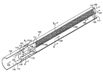
FIG. 3 shows a longitudinal cross-section of the first alternative
embodiment of the present invention. In this embodiment, the apparatus
comprises a catalytic reactor 100 comprised of a housing 102 having an
entrance
and an exit, and defining at least one aperture 107. A plate 115 is positioned
within
the housing 102 defining a first zone 105 and a second zone 106. The aperture
107
is in fluid communication with the second zone 106.
At least two conduits 110 made from a heat conducting material and
adapted for conducting a fluid are positioned within the housing 102. The
conduits
have an entrance 116, an exit 117 with an exit periphery 113, an interior
surface 112,
and an exterior surface 111. The conduits 110 are positioned within the
housing
102 such that the conduits 110 penetrate plate 115 thereby having the conduit
CA 02403092 2002-09-16
WO 01/71252 PCT/US01/40297
entrances 116 in fluid communication with the first zone 105 and the conduit
exits
within the second zone 106. A first fluid 120 entering first zone 105 must
enter
second zone 106, if at all, by exiting conduits 110. The conduit exit
periphery 113
positions the conduits 110 relative to each other and the housing interior
surface
5 114.
The flow path 123 within housing 102 is defined by the conduit
exterior surfaces 111. The flow path extends between the aperture 107 and the
flow
path exits, which are defined by the conduit exit peripheries 113. The flow
path
123 can have numerous physical configurations that are application dependent.
In
10 general, the flow path must permit the diffusion of the entering second
fluid 127 in
a manner to ensure the second fluid 127 can enter all the passages containing
catalyst downstream therefrom. Those skilled in the art will appreciate the
numerous structures that can be designed based upon the specific application,
thus
the invention should not be considered limited to the flow paths depicted in
the
15 embodiments presented.
FIG. 3 depicts a partitioned flow path. Just downstream of the
aperture 107, the flow path 123 allows for the second fluid 127 to disperse
throughout housing 102. Further downstream however, the flow path has been
subdivided into a plurality of smaller passages. Partitioned means that the
fluid is
essentially confined to the smaller passages. Partitioning is accomplished by
physical means, such as a solid barrier or by contact (close proximity) of
surfaces.
In this embodiment, the subdivision into a plurality of small passages is
accomplished by contact, expanding the cross-section of the conduits 110 so
that
they touch.
A catalyst 103 has been deposited on a portion of the conduit exterior
surface 111. Catalyst can be deposited anywhere in the flow path. It is
preferred
that the catalyst be deposited downstream of aperture 107.
FIG. 4 is a cross-sectional view of the housing 102 taken through
aperture 107 looking downstream showing the definition of the flow path 123 by
the conduit exterior surfaces 111 within housing 102. To allow a second fluid
127
upon entering the second zone to diffuse, the cross-sections of the conduits
110 are
sized to permit the fluid to easily flow around the conduit exterior surfaces
111.
As shown in FIG. 5, which is a cross-sectional view of the housing 102
approximately mid-way between the aperture 107 and the flow path exits 125,
the
conduit 110 cross-sections have been sized such that the conduit exterior
surfaces
CA 02403092 2002-09-16
WO 01/71252 PCT/US01/40297
16
covered with catalyst 103 touch, or nearly touch, one another or the housing
interior surface 114. The sizing of the conduit 110 cross-sections in this
manner
effectively divides the flow path 123 into a plurality of passages.
FIG. 6 shows an end view of the catalytic reactor 100 looking
upstream from the discharge end of the catalytic reactor 100. The conduit exit
peripheries 113 define the flow path exits 125 as well as assure the conduit
exits 117
are interspersed with the flow path exits 125. In this embodiment, the conduit
exit
peripheries 113 provide the structure which holds the conduits 110 in position
by
contacting the housing interior surface 114 within the housing 102.
FIG. 7 shows a longitudinal cross-section of another embodiment of
the present invention. This embodiment is the same as that depicted in FIG. 3
except that the flow path 123 is of a different configuration. In this
embodiment,
the flow path is unpartitioned. Unlike the embodiment depicted in FIG. 3, the
conduit cross-sections are sized to allow the second fluid 127 to flow around
the
conduits throughout the entire length of the flow channel 123. The flow path
after
the initial dispersion area can be partitioned, unpartitioned, or a
combination. In
the embodiment shown in FIG. 7, the conduit exit peripheries 113 define the
flow
path exits 125 as well as assure the conduit exits 117 are interspersed with
the flow
path exits 125. In this embodiment, the conduit exit peripheries 113 provide
the
structure which holds the conduits 110 in position by contacting the housing
interior surface 114 within the housing 102. While flares are shown, it is not
required and the invention should not be considered so limited.
FIG. 8 shows a longitudinal cross-section of another embodiment of
the present invention. This embodiment is the same as that depicted in Figure
3
except that the flow path 123 is partitioned by a physical barrier. The
conduit
exterior surfaces are integrated into a structure resembling a monolith. In
this
embodiment the flow path 123 is still considered defined by the conduit
exterior
surfaces 111, and the catalyst 103 is considered deposited thereon.
FIG. 9 shows a longitudinal cross-section of the embodiment depicted
in FIG. 3 with a plenum 130 added upstream of the aperture 107 and in fluid
communication therewith. If a plenum 130 is employed multiple apertures 107
are
preferred. A plenum 130 can be incorporated into any of the previously
discussed
embodiments.
FIG. 10 shows a longitudinal cross-section of another embodiment of
the present invention very similar to that disclosed in FIG. 3. This
embodiment,
CA 02403092 2002-09-16
WO 01/71252 PCT/US01/40297
17
however, is based on a simplified housing structure. In this embodiment, the
catalytic reactor 200 comprises a housing 202 having an exit, and defining at
least
one aperture 207.
At least two conduits 210 made from a heat conducting material and
adapted for conducting a fluid are positioned within the housing 202. The
conduits
have an entrance 216, an exit 217 with an exit periphery 213, an interior
surface 212,
and an exterior surface 211. The conduits 210 are positioned within the
housing
202 such that the conduits 210 penetrate the housing thereby having the
conduit
exits within the housing 202 and the conduit entrances 216 opening to an area
outside the housing 202. A first fluid 220 entering conduits 210 enters
housing 202,
if at all, by exiting conduits 210. The conduit exit periphery 213 positions
the
conduits 210 relative to each other and the housing interior surface 214.
FIG. 10 depicts an unpartitioned flow path. This embodiment,
however, has all the flexibility of the first embodiment. As with the first
embodiment a plenum could also be incorporated.
For application in a gas turbine, the catalytic reactor must be
integrated into the gas turbine combustion system. For gas turbine engines
using a
combustor shell to contain the high-pressure gases within the combustion
section
and to provide a sealed flow path from compressor exit to turbine inlet, the
reactor
housing is relieved of the need to contain high pressure. The fuel-rich
fuel/air
mixture advantageously should be uniformly mixed prior to delivery to the flow
path. Mixing of fuel and air within the flow path is also feasible if the
reactor is
designed accordingly.
As a general design rule, it is desirable to design the catalytic reactor
such that the catalytic reaction approaches its maximum possible extent at all
expected operating conditions, so that variations in chemical reaction rates
and
mass transfer rates do not affect the catalytic reactor output. Thus,
sufficient
catalyst coating should be applied that O2, the limiting reactant, is
substantially
consumed in the flow path. Oz conversions greater than 50 percent are
preferred,
and Oz conversions greater than 75 percent are most preferred.
Sufficient catalyst coating means sufficient loading, on a weight basis,
as well as sufficient geometric surface area of catalyst. Insufficient loading
will
result in an insufficient number of catalytic reaction sites, and insufficient
geometric surface area will result in insufficient total mass transfer from
the gas-
phase to the catalytic surface. In either case, insufficient catalyst means
that Oz
CA 02403092 2002-09-16
WO 01/71252 PCT/US01/40297
18
conversions will be below the preferred levels. The required loading and the
required geometric surface area will depend upon operating conditions (e.g.
reactant temperature, pressure, velocity, composition) and catalyst activity,
and can
be determined by methods known in chemical engineering practice.
The catalyst coating used in the present invention, where the fuel is a
hydrocarbon and oxygen is the oxidizer, may have as an active ingredient
precious
metals, group VIII noble metals, base metals, metal oxides, or any combination
thereof. Elements such as zirconium, vanadium, chromium, manganese, copper,
platinum, palladium, osmium, iridium, rhodium, cerium, lanthanum, other
elements of the lanthanide series, cobalt, nickel, iron, and the like may be
used.
The catalyst may be applied directly to the substrate, or may be applied to an
intermediate bond coat or washcoat composed of alumina, silica, zirconia,
titania,
magnesia, other refractory metal oxides, or any combination thereof.
The catalyst-coated substrate may be fabricated from any of various
high temperature materials. High temperature metal alloys are preferred,
particularly alloys composed of iron, nickel, and/or cobalt, in combination
with
aluminum, chromium, and/or other alloying materials. High temperature nickel
alloys are especially preferred. Other materials which may be used include
ceramics, metal oxides, intermetallic materials, carbides, and nitrides.
Metallic
substrates are most preferred due to their excellent thermal conductivity,
allowing
effective backside cooling of the catalyst.
Fuel types include hydrocarbons, hydrocarbon oxygenates, and
blends thereof. Suitable gaseous fuels include natural gas, methane, and
propane.
Suitable liquid fuels include gasoline, kerosene, No. 1 heating oil, No. 2
heating oil,
and conventional aviation turbine fuels such as Jet A, Jet B, JP-4, JP-5, JP-
7, and JP-
8. "Hydrocarbon" not only refers to organic compounds, including conventional
liquid and gaseous fuels, but also to gas streams containing fuel values in
the form
of compounds such as carbon monoxide, organic compounds, or partial oxidation
products of carbon containing compounds. If the fuel is a liquid, it should be
vaporized or atomized before mixing with air or while being mixed with air.
Example 1
A catalytic reactor similar to that illustrated in FIG. 9 was fabricated
for dual air-source testing, with separate air flow controls for the flow path
and the
CA 02403092 2002-09-16
WO 01/71252 PCT/US01/40297
19
conduits: A single fuel source was employed. As shown in FIG. 9, a plenum
supplied the fuel-rich fuel/air mixture to the flow path through multiple
apertures.
At the downstream end of the catalytic reactor, the product stream exited the
flow
path via the interstitial space created by the conduit peripheries. The
cooling air
exited the conduits at this same axial location, and mixed with the product
stream.
The conduits, specifically tubes, were 10 inches in length with an
outside diameter of .188 inches, and a material thickness of 0.010 inches. One
end
of the tube was expanded at a constant angle of 4 degrees until the cross-
section
was increased about 30 percent, to a final inside diameter of 0.255 inches. A
flat
segment was provided on the 0.255-inch-diameter flared section of about 0.1
inches
length. The housing was sized such that seven tubes could be accommodated and
positioned therein by the flares. The tubes were inserted through the plate
and
brazed thereto to form a tight seal.
A catalyst was deposited on approximately 8.5 inches of the exterior
of the tubes. To prepare for catalyst application, an alumina washcoat was
first
applied, with a loading of approximately 20 to 40 mg/square-inch. Palladium
catalyst was then applied to the washcoat, with a loading of approximately 10
to 15
mg/square-inch. There was some variation in both washcoat and catalyst
loading.
The catalytic reactor was installed in a refractory-lined cylindrical
pressure vessel to permit testing of the catalytic reactor at pressure. A
fuel/air inlet
pipe penetrated the vessel wall through a high-pressure fitting, and mated
with a
sealing fitting at the fuel/air inlet plenum of the catalytic reactor. Cooling
air was
supplied to the conduits by a separate line which entered the pressure vessel
at its
upstream end. Upon exiting the catalytic reactor, the combustible gas mixture
(the
combined product stream and the cooling stream) entered a 0.495-inch inside-
diameter extension tube, followed by a nozzle block that tapered down to a
0.375-
inch inside-diameter at its exit. The total length from the conduit exits to
the
downstream end of the nozzle block was approximately 15 inches. Immediately
downstream of the nozzle block exit was a sudden expansion to a 3-inch-
diameter
burnout zone for combustion completion.
At 10 atm pressure, the catalytic reactor was operated at an inlet
reference velocity of 250 ft/s. The inlet reference velocity is defined as the
velocity
which would result inside the catalytic reactor housing without the conduits.
In
other words, if all fuel and air entering the catalytic reactor (including
both the
CA 02403092 2002-09-16
WO 01/71252 PCT/US01/40297
conduit cooling air and the fuel-rich fuel/air mixture) were mixed before
reaction
to form an aggregate mixture at an aggregate temperature and mass flow rate,
and
if this aggregate mixture had a uniform velocity throughout the reactor, and
if the
conduits were of zero thickness, then the velocity inside the reactor housing
would
5 be 250 ft/s..
At the 10 atm, 250 ft/s inlet reference velocity condition, 10 percent of
the total air was delivered to the flow path, and 90 percent of the total air
was
delivered to the conduits for cooling. The fuel flow rate was set to provide
an
overall 0.5 equivalence ratio in the fuel-lean fuel/air mixture downstream of
the
10 catalyst, giving an equivalence ratio of 5.0 for the fuel-rich fuel/air
mixture. The
cooling air was heated to 950 degrees F at the catalytic reactor inlet. The
fuel-rich
fuel/air mixture entered at room temperature (nominally 60 degrees F). The
resulting overall adiabatic flame temperature in the downstream burn-out zone
was approximately 2800 degrees F. NOx emissions of less than 5 ppmv (corrected
15 to 15 percent excess OZ dry) were measured from the downstream sampling
port
(14 inches downstream of the sudden expansion plane), indicating that all
burning
took place in a well-mixed mode at flame temperatures in the vicinity of 2800
degrees F. As desired, there was no high-NOx-producing combustion during
mixing of the cooling stream and the product stream. In this configuration at
these
20 conditions, the conduit exits act as multiple jets surrounded by a co-
flowing
product stream. The jets, nominally 0.255 inches in diameter, allowed rapid
mixing
at this small scale and helped to prevent ignition and burning of the
reactants
within the product stream before mixing was achieved. At the conditions given,
the maximum catalyst substrate temperature was measured to be below
approximately 1800 degrees F, which is below the substrate and catalyst
material
failure point. Gas sampling from the downstream end of the flow path indicated
that approximately 90 percent of the OZ present in the fuel-rich fuel/air
mixture
was consumed prior to exiting the flow path.
These results confirm that the method and apparatus of the present
invention are capable, at gas-turbine-type operating conditions, of providing
the
desired result: fuel-rich catalytic reaction followed by stable, low-NOx gas-
phase
combustion, with well-moderated catalyst operating temperatures.
Although the invention has been described in considerable detail, it
will be apparent that the invention is capable of numerous modifications and
CA 02403092 2002-09-16
WO 01/71252 PCT/US01/40297
21
variations, apparent to those skilled in the art, without departing from the
spirit
and scope of the invention.