Note: Descriptions are shown in the official language in which they were submitted.
CA 02403094 2002-09-16
WO 01/71410 PCT/US01/08422
HIGH ACUITY LENS SYSTEM
BACKGROUND OF THE INVENTION
Description of the Related Art
Stereoscopic systems provide a viewer with a three-dimensional representation
of a
scene (or an object), using two or more, two-dimensional representations of
the scene. The
two-dimensional representations of the scene are taken from slightly different
angles.
The goal of stereoscopic systems is to produce one or more binocular views of
a
scene to the viewer. A full-parallax view accurately simulates depth
perception irrespective
of the viewer's motion, as it would exist when the viewer observes a real
scene.
Stereoscopic systems include autostereoscopic systems and non-autostereoscopic
systems. Non-autostereoscopic systems require a viewer to use a device, such
as viewing
glasses, to observe the three-dimensional view, while the three-dimensional
effect of
auto stereoscopic systems may be observed by viewing the system directly.
Early stereoscopic devices used prismatic, total internal reflection (TIR) to
simultaneously present two views of a scene, such as the Swan Cube. Prismatic
TIR
allowed the views to be presented to the viewer such that each of the viewer's
eyes was
presented one of the two images, thus creating a perception of depth.
Prismatic devices
simulate depth perception for only a single viewing angle.
After the introduction of transparent plastic optics, autostereoscopic devices
using
one-dimensional arrays of cylindrical lenses (known as lenticular lenses) were
created. A
lenticular lens array has an associated array of composite strip images. Each
lenticular lens
presents the viewer a selected portion of its strip image such that the
combined presentation
of all of the lenticular lenses presents a three-dimensional view of the
scene.
Devices using lenticular lenses have several shortcomings. First, because the
lenticular lenses are cylindrical (i.e., they have optical power in a single
dimension), they
produce parallax only on a horizontal viewing axis. If the viewer's viewing
angle departs
from the horizontal viewing axis, the three-dimensional representation ceases
to exist.
Second, the lenticular lenses are highly astigmatic, and therefore, the viewer
cannot bring
the three-dimensional representation fully into focus. Third, if the two-
dimensional images
require illumination through the lenticular arrays (i.e., the images are not
self-radiant, or the
images are not printed on a transparent or translucent material that is
capable of
backlighting), the three-dimensional presentation will have uneven radiance
resulting from
uneven distribution within the array.
CA 02403094 2002-09-16
WO 01/71410 PCT/US01/08422
2
Another autostereoscopic system uses an array of spherical (or aspherical)
lenses.
Spherical lens array systems have an associated two-dimensional array of
microimages.
Each microimage is a two-dimensional view of a scene, captured from a slightly
different
angle. Unlike lenticular lenses, spherical lenses have optical power in two
dimensions, thus
allowing the viewer to maintain a three-dimensional representation of a scene
despite
departing from the horizontal viewing axis.
Each spherical lens presents the viewer a selected portion of a corresponding
microimage such that the combined presentation of all of the spherical lenses
presents a
three-dimensional view of a scene. Ideally, each lens system of the lens array
corresponds to
a single microimage, such that when a viewer views the microimages through the
lens array,
each lens system transmits a single color or tone, from a selected portion of
a single,
corresponding microimage.
The shortcomings of spherical arrays have included that lenses in a lens
arrays have
excessive aberrations and a tendency to transmit light from multiple
microimages. Both of
these shortcomings have resulted in reduced image quality.
An additional advantage of spherical (or aspherical) arrays of lenses is there
ability
to capture arrays of microimages for use with three-dimensional viewing
systems. The
process of capturing arrays of microimages is known as integral imaging. An
image
captured by a spherical lens array is initially pseudoscopic, but may be made
orthoscopic by
reproduction of a captured image using a second array.
A difficulty encountered in capturing and reproducing images is optical
crosstalk
between lens systems of the array. Crosstalk causes overlap of adjacent
images, resulting in
degradation of the microimages. Solutions to crosstalk have ranged from
modifications of
the scene when creating the microimages, to optomechanical modifications of
the lens
arrays. Optomechanical modifications of the lens arrays have included baffles
that limit the
field of the lens systems comprising a lens array. The baffled lens systems
are said to be
field-limited. And a field-limited system whose field does not overlap the
field of adjacent
lens systems is said to be "isolated." Solutions to crosstalk have been costly
to implement.
SUMMARY OF THE INVENTION
An aspect of lens systems of the present invention is a high acuity lens
system
comprising three optical boundaries having optical power. The lens system
comprises a first
CA 02403094 2010-08-16
53053-3
3
boundary having a radius of curvature R, a second boundary located
substantially
a distance R from the first surface, and a third surface located at least
0.05R from
the second boundary.
Another aspect of lens systems of the present invention is a lens
array having a lens system that is "optically field-limited." An optically
field-limited
system is a system wherein the edges of the field of the system are determined
by
the optical properties of lens material of the system. Accordingly, light
within the
field of a lens is substantially transmitted by the lens, and light at greater
field
angles than the edges of the field is substantially reflected by a surface of
the lens
system, using total internal reflection.
There is also provided a lens system comprising, in series: a first
convex surface; a first concave surface optically coupled to the first convex
surface via a first material; and a second convex surface optically coupled to
the
first concave surface via a second material having a lower index of refraction
than
the first material, the first convex surface, the first concave surface, and
the
second convex surface having surface positive, negative, and positive optical
powers, respectively, such that light incident on the first convex surface
outside a
predetermined angle is prevented from passing through the first concave
surface.
CA 02403094 2009-12-21
53053-3
3a
BRIEF DESCRIPTION OF THE DRAWINGS
Non-limiting embodiments of the present invention will be described by
way of example with reference to the accompanying drawings, in which:
15 FIGS. IA illustrates aberration in uncorrected arrays;
FIG. IB illustrates aberration in a lenticular array;
FIG. 2A-FIG.2D are schematic diagrams of embodiments of a lens systems
illustrating a focal situations appropriate for use with the present
invention;
FIG. 3A is a cross sectional side view of one example of an embodiment of a
three-
20 element lens system according to the present invention;
FIG. 3B is a cross sectional side view of one example of an embodiment of a
two-
element lens system according to the present invention;
FIG. 4A is a cross sectional side view of one example of a discrete lens
system that
is object-side optically field-limited;
25 FIG. 4B is transmission curve of an object-side optically field limited
lens system, as
a function of location in an image plane;
FIG. 5A is a cross sectional side view of one example of an embodiment of a
lens
system that is object-side optically field-limited;
FIG. 5B is a top view'of a lens system that is object-side optically field-
limited;
30 FIG. 5C is an example of cross sectional side view of a lens having an
equiangular
surface;
FIG. 5D is an example of cross sectional side view of a lens having an
equiangular
surface that is equiangular at the critical angle;
CA 02403094 2002-09-16
WO 01/71410 PCT/US01/08422
4
FIG. 5E is an example of cross sectional side view of a lens having an
equiangular
surface that is equiangular at the critical angle;
FIG: 6A is a cross sectional side view of one example of an embodiment of a
discrete lens system that is image-side optically field-limited;
FIG. 6B is transmission curve of a image-side optically field limited lens
system, as
a function of location in an object plane;
FIG. 7A is a cross sectional side view of one example of an embodiment of a
lens
system that is image-side optically field-limited;
FIG. 7B is a top view of lens system that is image-side optically field-
limited;
FIG. 7C is a cross sectional view of a lens system having an equiangular
surface;
FIG. 7D is a cross sectional view of a lens system having an equiangular
surface
that is equiangular at the critical angle;
FIG. 8 is a ray trace of an uncorrected lens system;
FIG. 9 is a ray trace one example of a three-element lens system according to
the
present invention;
FIG. 10 a is a ray trace of one example of a two element lens system according
to the
present invention;
FIG. I OB is a ray trace illustrating field limitation;
FIG. 11 is lens system according to the present invention having finite
conjugates;
FIG. 12 is an MTF of an uncorrected lens system;
FIG. 13 is an MTF of one example three-element lens system according to the
present invention
FIG. 14 is an MTF of one example of a two-element lens system according to the
present invention;
FIG. 15 is an MTF of one example of a finite conjugate lens system according
to the
present invention;
FIG. 16A is transmittance curve as a function of the critical angle;
FIG. 16B is a curve illustrating transmittance through an optically field
limited
system and a vignetted lens system;
FIG 16C is a plot of two overlapping image fields in a lens array according to
the
present invention;
FIG. 17 is a perspective view an optically field limited lens array;
FIG. 18 is a perspective view of a three-element lens array;
CA 02403094 2002-09-16
WO 01/71410 PCT/US01/08422
FIG. 19A-19D are cross sectional side views of embodiments of two-element lens
system according to the present invention;
FIG. 20A-20B are cross sectional side views of a three-element lens system
according to the present invention;
5 FIG. 21 is a cross sectional side view of a reproduction system according to
the
present invention;
FIG. 22 is a plan view of the image plane of a reproduction system according
to the
present invention;
FIG. 23 is a schematic view of one cell of the image plane of the master array
of a
reproduction system according to the present invention;
FIG. 24 is a top view of multiple lens cells of a lens array according to the
present
invention lens system
FIG. 25 is a schematic view of one cell of the image plane of a duplicate
array within
a reproduction system according to the present invention;
FIG 26A is a sectional side view of a three element lens illustrating on axis
performance of a lens system according to the present invention;
FIG 26B is a sectional side view of a three element lens illustrating off axis
performance of a lens system according to the present invention;
FIG 26C is a sectional side view of a three element lens illustrating diffuse
illumination of the image plane from prismatic diffusers;
FIG 27A is a sectional side view of a two element lens illustrating on axis
performance of a lens system according to the present invention;
FIG 27B is a sectional side view of a two element lens illustrating off axis
performance of a lens system according to the present invention;
FIG 27C is a sectional side view of a two-element lens illustrating diffuse
illumination of the image plane from prismatic diffusers;
FIG 28A is a schematic view of the emission of light from a conventional array
of
lenses;
FIG 28B is a schematic view of the emission of collimated light from a lens
array
according to the present invention
FIG 28C is a schematic view of the emission of light at a predetermined
vergence
angle
FIG 29A is a plan view rectangular microimage;
CA 02403094 2002-09-16
WO 01/71410 PCT/US01/08422
6
FIG 29B is a plan view of a hexagonal microimage;
FIG 29C is a plan view of a first orientation of a stepped rectangular
microimage;
FIG 29D is a plan view of a second orientation of a stepped rectangular
microimage;
FIG 30A is schematic top view of a first orientation of a stepped rectangular
microimage and canted square lens array;
FIG 30B is schematic top view of a second orientation of a stepped rectangular
microimage and canted square lens array;
FIG 31 is a plan view of a stepped cruciform microimage
FIG 32A is a plan view of a coarsely stepped rectangular tiling of
microimages;
FIG 32B is a plan view of a moderately stepped rectangular tiling of
microimages;
FIG 32C is a plan view of a finely stepped rectangular tiling of microimages.
SUMMARY OF THE INVENTION
A lens system, having a conjugate point comprising a first convex surface
having a
radius of curvature R. The system further includes a first concave surface
optically coupled
to the first convex surface via a first material, the first concave surface
positioned a distance
substantially equal to R from the first convex surface. The system further
includes a second
convex surface optically coupled to the first concave surface via a material
having a lower
index of refraction than the first material, the second convex surface
positioned at least a
distance equal to 0.05R from the first concave surface.
A lens array, comprising a plurality of lens systems, the lens systems
comprising a
first convex surface having a radius of curvature R, and a first concave
surface optically
coupled to the first convex surface via a first material, the first concave
surface positioned a
distance substantially equal to R from the first convex surface. The lens
array further
comprising a second convex surface optically coupled to the first concave
surface via a
material having a lower index of refraction than the first material, the
second convex surface
positioned at least a distance equal to 0.05R from the first concave surface.
Another aspect of the invention is a reproduction system, comprising a first
array of
lenses comprising a first plurality of lens systems, the first array of lenses
having a object
plane, each of the first plurality of lens systems having an optical axis, and
a second array of
lenses comprising a second plurality of lenses, the second array of lenses
having an image
plane, each of the second plurality of lenses having an optical axis, the
second array of
lenses optically coupled to one lens system of the first array of lenses. At
least one lens
CA 02403094 2002-09-16
WO 01/71410 PCT/US01/08422
7
system of the lens systems of the first plurality of lenses, or one lens
systems of the second
plurality of lenses, is an optically field-limited surface for one of the
image plane and the
object plane.
A microimage capture system for capturing a plurality of microimages of an
object,
comprising a photo sensitive medium. The system comprising a lens array
optically coupled
to the photo sensitive medium and including a first convex surface having a
radius of
curvature R. The system further comprising a first concave surface optically
coupled to the
first convex surface via a first material, the first concave surface
positioned a distance
substantially equal to R from the first convex surface, and a second convex
surface
optically coupled to the first concave surface via a material having a lower
index of
refraction than the first material, the second convex surface positioned at
least a distance
equal to 0.05R from the first concave surface.
A three-dimensional viewing system for producing a three dimensional
representation comprising a plurality of microimages, and a lens array,
optically coupled to
the plurality of microimages The lens array comprising a lens having a first
convex surface
having a radius of curvature R, and a first concave surface optically coupled
to the first
convex surface via a first material, the first concave surface positioned a
distance
substantially equal to R from the first convex surface. The lens further
having a second
convex surface optically coupled to the first concave surface via a material
having a lower
index of refraction than the first material, the second convex surface
positioned at least a
distance equal to 0.05R from the first concave surface.
An optical system, comprising a lens system, and a photic element optically
coupled
to the lens system. The lens system comprising a first area symmetric about a
first axis,
having a dimension X along the first axis, and a dimension Y along a second
axis, and a
second area contiguous with the first area and symmetric about the second axis
having a
dimension A along the first axis and a dimension B along the second axis,
wherein
dimension A is smaller than dimension X.
A lens system for transmitting light from an object point, comprising a lens
having a
first surface, a second surface having a critical angle, and a first index of
refraction, and a
region adjacent to the second surface and having an index of refraction lower
than the first
index of refraction. Each ray originating from the object point impinges the
second surface
substantially at the critical angle.
CA 02403094 2002-09-16
WO 01/71410 PCT/US01/08422
8
DETAILED DESCRIPTION OF THE INVENTION
Throughout the description below, features having common numbers have common
function.
The invention includes features that can reduce aberrations in lens arrays.
FIGS. 1A
and 1B are cross sectional side views of a lens element that illustrate
aberration in
uncorrected lens systems. In uncorrected element U1 in FIG. 1, the defect of
focus is
predominantly due to spherical aberration. Marginal rays converge at a shorter
focus than
rays entering near the axis of the lens. In uncorrected element U2 in FIG. 1B,
it may be
seen that, in cylindrical lens elements, the defect of focus is further
compounded by
astigmatism. A graphic element on display image plane IPD of U2 may be
imagined as
radiating point PR emitting in all directions. A ray trace on the longitudinal
axis of a
cylindrical lens, as shown at the left of FIG. lB produces a different
geometry from that on
the transverse axis, shown on the right. The combined geometries produce
astigmatic
cylindrical wavefront CW. Systems within the invention propose the use of
rotationally-
symmetrical microlens arrays, which are inherently free of astigmatism, and
which include
aspheric surfaces that can significantly reduce the remaining defects of
focus.
A lens system according to the present invention can be designed to operate as
a
focal or an afocal system depending on the application of the system. Afocal
systems
include both infinite and virtual object planes. FIG. 2A- FIG. 2D are
schematic drawings of
various focal situations appropriate for use with the present invention.
FIG. 2A is a cross sectional view of a lens system 200 according to the
present
invention. Lens system 200 has an image plane 202. Image point 204 is located
on image
plane 202. Lens system 200 is a focal system and converges light from image
point 204 to a
finite object point 206. Field limited lens systems having a finite object
point 206 are useful
in devices such as telecommunication devices, or reproduction systems as
described below.
FIG. 2B is a cross sectional view of a lens system 210 according to the
present
system. Lens system 210 has an image plane 212. Image point 214 is located on
image
plane 212. Lens system 210 is an afocal system and focuses light from image
point 214 to
an infinite object plane. A lens system having an infinite object plane can be
useful in
devices to be viewed by a human being, or in optical communications. However,
when
viewing an array of collimating lens systems having an outer surface dimension
smaller than
CA 02403094 2002-09-16
WO 01/71410 PCT/US01/08422
9
the viewer's pupil diameter D, the viewer's pupil may be underfilled allowing
surrounding
sources of light such as adjacent collimated lens systems to degrade the
viewer's ability to
focus the output of lens 210. Diameter D is referred to as the pupillary
diameter.
FIG. 2D is a cross sectional view of a lens system 220 according to the
present
invention. Lens system 220 has an image plane 222. Image point 224 is located
on image
plane 222. Lens system 220 is an afocal system, which diverges light from
image point 224
to form a virtual image point 226. A viewer receiving light from lens system
220 would
observe a point appearing to originate behind lens system 220.
Lens systems having a virtual object point are useful in devices designed for
viewing
by a human being. In particular, in lens systems having an outer surface
dimension smaller
than the pupillary diameter D, the lens system can be designed to fill a
viewer's pupil. In a
system to be viewed by a human being, pupillary diameter D is preferably
approximately
equal to the diameter of the pupil of the human eye, at an anticipated viewing
distance S.
FIG. 2D is a cross sectional view of a lens system 230 according to the
present
invention. Lens system 230 has an image plane 232. Image point 234 is located
on image
plane 232. Lens system 230 is a focal system and converges light from image
point 234 to
form a finite object point 236. A viewer receiving light from lens system 230
would observe
a point appearing to originate in front of lens system 220.
Object point 236 is located a distance T from lens system 230. Lens system 230
is
designed to be viewed by an viewer at a distance S from lens system 230, where
S is greater
than T, such that the light would fill the viewer's pupil at distance S. A
viewer observing
lens system 230 would receive a image appearing to originate in front of lens
system 230.
Features described with reference to FIG 2c-FIG 2d will be applied to array
systems
of the present invention to improve the quality of systems to be viewed by a
human being.
Throughout the specification the following definitions will apply. The phrases
"object plane" and "image plane" refer to conjugate planes of a lens system or
an array of
lens systems. However, the terms "object" and "image" are non-limiting, and
image planes
and object planes can be photo-emitting, photo-detective, both, or neither,
depending on the
specific application of a lens system. The phrase "object point" refers to
points on either a
finite or infinite object plane of a lens system. The phrase "image point"
refers to a point on
an image plane of a lens system.
FIG. 3A is a cross sectional side view of one example of an embodiment of a
high
acuity three-element lens system 100 according to the present invention. Lens
system 100
CA 02403094 2002-09-16
WO 01/71410 PCT/US01/08422
has an optical axis 110, and an image plane 112. Rays of light 105 correspond
to an object
point and an image point 120. Lens 100 includes a first lens 125, a second
lens 150, and a
region 166 between lens 125 and lens 150.
Lens system 100 is any multielement optical system, which includes a first
lens 125,
5 a second lens 150, and a region 166 between lens 125 and lens 150, wherein
region 166 is a
low index material, other than air. Lens system 100 is any optical system,
which includes a
first lens 125, a second lens 150, and a region 166 between lens 125 and lens
150, wherein
region 166 is a material, other than air, wherein region 166 forms a third
lens 175 between
first lens 125 and second lens 150. Lens system 100 is any optical system,
which includes a
10 first lens 125, a second lens 150, and a region 166 between lens 125 and
lens 150, wherein
region 166 is a material, other than air, wherein region 166 forms a third
lens 175 between
first lens 125 and second lens 150, and wherein a first surface 176 and a
second surface 177
of the third lens 175 are defined by the first lens 125 and second lens 150.
First lens 125 has a first surface 126, a second surface 127, and is
constructed of a
material having a relatively high index of refraction. Second lens 150 has a
first surface
151, a second surface 152 and is constructed of any material having a
relatively high index
of refraction.
First lens 125 and second lens 150 can be constructed of any material having a
relatively high index of refraction that is optically transparent. First lens
125 and second
lens 150 can be constructed of any material having a relatively high index of
refraction that
is optically transparent at optical or infrared wavelengths. First lens 125
and second lens 150
can be constructed of any material having a relatively high index of
refraction that is
optically transparent at optical or infrared wavelengths, and is configurable
into an optical
lens element. First lens 125 and second lens 150 can be constructed of any
material having a
relatively high index of refraction that is optically transparent at optical
or infrared
wavelengths, and is configurable into an optical lens element, wherein the
index of
refraction is approximately equal to 1.6. Polycarbonate, styrene, polyamides,
polysulfones,
optical glasses, or infrared-transmitting materials such as germanium are
examples of
materials appropriate for constructing lenses 125 and 150. It is understood
that other
materials having a relatively high index of refraction can be used.
Third lens 175 occupying region 166 can be constructed of any material having
an
index of refraction lower than first lens 125. and second lens 150. Third lens
175 can be
formed of any material having an index of refraction lower than first lens 125
and second
CA 02403094 2002-09-16
WO 01/71410 PCT/US01/08422
11
lens 150, wherein the index of refraction is between 1.29 and 1.42. Examples
of materials
appropriate for constructing third lens 175 are low-index fluouropolymers,
optical fluids,
gels, ceramics, optical foams, slurries, and compounds. One specific example
of an optical
foam is Sol-Gel. It is understood that other materials having a relatively low
index of
refraction can be used.
Three-element lens system 100 has three optical boundaries that have non-zero
optical power, first surface 126, second boundary 190, and third boundary 191.
First surface
126 has a first vertex 102 and a radius of curvature R. First surface 126 is
any optical
boundary having positive power. First surface 126 is any optical boundary
having positive
power and a convex surface.
Second boundary 190 is at the interface of second surface 127 of first lens
125 and
the first surface 176 of the third optical lens 175. Second boundary 190 is
any optical
boundary having a negative power. Second boundary 190 is any optical boundary
having a
negative power such that second surface 127 of first lens 125 has a concave
curvature.
Second boundary 190 is any optical boundary having a negative power such that
second
surface 127 of first lens 125 has an oblate, concave curvature. Second
boundary 190 is any
optical boundary having a negative power such that second surface 127 of first
lens 125 has
an oblate, concave curvature, wherein second boundary 190 is located
substantially a
distance R from first surface 126. Second boundary 190 can be located between
0.7 R and
1.4 R away from first vertex 102.
Third boundary 191 is the interface of first surface 151 of second lens 150,
and the
second surface 177 of the third lens 175. Third boundary 191 is any optical
boundary
having a positive power. Third boundary 191 is any optical boundary having a
positive
power such that first surface 151 of second lens 150 is convex. Third boundary
191 is any
optical boundary having a positive power such that first surface 151 of second
lens 150 is a
prolate or reflexed, convex surface. For purposes of this disclosure the term
"reflexed" shall
mean a boundary having regions of locally convex curvature and regions of
locally concave
curvature. Second boundary 191 is located at least 0.05 R from first boundary
190 at optical
axis 110.
Fourth surface 152 is an optical boundary. Fourth surface 152 is any optical
boundary having a continuous surface. Optical surface 152 is any optical
boundary having a
continuous surface and zero optical power. Preferably, fourth surface 152 is a
continuous
surface, having zero optical power disposed at the image plane 112 of lens
system 100.
CA 02403094 2002-09-16
WO 01/71410 PCT/US01/08422
12
Optionally, lens system 100 may include one or more surfaces having coatings
for
antireflection, antiabrasion or heat resistance purposes. As an alternative or
a compliment to
antireflection coatings, a sub-wavelength microstructure may be used to reduce
reflections.
Sub-wavelength microstructures may be produced during the molding process if
lenses are
produced using a molding process. Additionally, any lens surface may be a
hybrid
refractive/diffractive surface, for reasons such as to reduce chromatic
aberrations.
FIG. 3B is a cross sectional side view of one example of an embodiment of a
two-
element lens system 300 according to the present invention. In a two-element
system, such
as lens system 300, the low index material of region 366 between lens 325 and
lens 350 is
void. One of ordinary skill in the art would understand that the term "void"
to include
vacuum, or a gas, such as air, wherein region 366 is an "air gap."
Lens system 300 is any multielement optical system, which includes a first
lens 325,
a second lens 350, and a region 366 between lens 325 and lens 350. Lens system
300 has an
optical axis 310, and an image plane 312. Rays of light 305 originate from an
object point.
First lens 325 has a first surface 326, a second surface 327. Second lens 350
has a
first surface 351, a second surface 352.
First lens 325 and second lens 350 can be constructed of any material that is
optically transparent. First lens 325 and second lens 350 can be constructed
of any material
that is optically transparent at optical or infrared wavelengths. First lens
325 and second lens
350 can be constructed of any material that is optically transparent at
optical or infrared
wavelengths, and is configurable into an optical lens element. First lens 325
and second lens
350 can be constructed of any material that is optically transparent at
optical or infrared
wavelengths, and is configurable into an optical lens element, wherein the
index of
refraction is approximately equal to 1.5-1.8. Polycarbonate, acrylic, styrene,
polyamides,
polysulfones, optical glasses, or infrared-transmitting materials such as
germanium are
examples of materials appropriate for constructing lenses 325 and 350. It is
understood that
other materials having a similar index of refraction can be used.
Lens system 300 has three optical boundaries that have non-zero optical power,
first
surface 326, second surface 327, and third surface 351. First surface 326 is
any optical
boundary having positive power. First surface 326 is any optical boundary
having positive
power and a convex surface. First surface 326 has a first vertex 302 and
radius of curvature
R.
CA 02403094 2002-09-16
WO 01/71410 PCT/US01/08422
13
Second surface 327 is an optical boundary having a negative power. Second
surface
327 is any concave optical boundary having negative power. Second boundary 391
is any
oblate, concave optical boundary having negative power. Second surface 327 is
any
concave, oblate optical boundary having negative power, located substantially
a distance R
from first surface 323. Second surface 327 can be located between 0.7 R and
1.4 R away
from first vertex 302.
Third surface 351 is an optical boundary having positive power. Third surface
351 is
any convex optical boundary having positive power. Third surface 351 is any
convex,
spherical optical boundary having positive power. Third surface 351 is any
convex,
spherical optical boundary having positive power. Alternatively third surface
351 can be
oblate, or prolate, or a higher order asphere. Third surface 351 is located at
least 0.05 R
from second surface 327 at optical axis 310.
Fourth surface 352 is an optical boundary. Fourth surface 352 is any optical
boundary having a continuous surface. Optical surface 352 is any optical
boundary having a
continuous surface and zero optical power. Preferably, fourth surface 352 is a
continuous
surface, having zero optical power disposed at the image plane 312 of lens
system 300.
Optionally, lens system 300 may include one or more surfaces having coatings
for
antireflection, antiabrasion or heat resistance purposes. As an alternative or
a compliment to
an antireflection coatings a sub-wavelength microstructure may be used to
reduce
reflections. Sub-wavelength microstructures may be produced during the molding
process if
lenses are produced using molding a molding process. Additionally, any lens
surface may
be a hybrid refractive/diffractive surface, for reasons such as to reduce
chromatic
aberrations.
As stated above, throughout the specification the following definitions will
apply.
The phrases "object plane" and "image plane" refer to conjugate planes of a
lens system or
an array of lens systems. However, the terms "object" and "image" are non-
limiting, and
image planes and object planes can be photo-emitting, photo-detective, both,
or neither,
depending on the specific application of a lens system.
The phrase "object point" refers to points on either a finite or infinite
object plane of
a lens system. The phrase "object-side field angle" refers to the angle, as
measured on the
object side of a lens system, formed between the optical axis of a lens system
and the ray of
light from an object point that is transmitted through the center of the
aperture stop of the
lens system. The phrase "edge of the object-side field" refers to the field
angle at the furthest
CA 02403094 2002-09-16
WO 01/71410 PCT/US01/08422
14
angular distance from optical axis for which the lens system transmission is
reduced to
substantially zero. In one embodiment, at the edge of the object-side field,
the lens system
transmits no more than 1% of the light incident on a lens system to the image
plane. It is
understood that the lens system discussed below have a single edge of the
object-side field
that is rotationally symmetric about the optical axis. Accordingly, in a cross
sectional view,
which includes the optical axis, the lens systems will have two edges of the
object-side field,
each edge a part of the single edge of the object-side field. The phrase
"object-side field"
refers to all points within the edges of the object-side field. Object points
having an object-
side field angle greater than the edge of the object-side field are said to be
"beyond the edge
of the field."
The phrase "image point" refers to points on either a finite or infinite image
plane of
a lens system. The phrase "image-side field angle" refers to the angle, as
measured on the
image side of a lens system, formed between the optical axis of a lens system
and the ray of
light from an image point that is transmitted through the center of the
aperture stop of the
lens system. The phrase "edge of the image-side field" refers to the field
angle at the furthest
angular distance from optical axis for which the lens system transmission is
reduced to
substantially zero. In one embodiment, at the edge of the image-side field,
the lens system
transmits no more than 1% of the light incident on a lens system to the object
plane. It is
understood that the lens system discussed below have a single edge of the
image-side field
that is rotationally symmetric about the optical axis. Accordingly, in a cross
sectional view,
which includes the optical axis, the lens systems will have two edges of the
image-side field,
each edge a part of the single edge of the image-side field. The phrase "image-
side field"
refers to all points within the edges of the image-side field. Object points
having an image-
side field angle greater than the edge of the image-side field are said to be
"beyond the edge
of the field."
FIG. 4A is a cross sectional side view of one example of an embodiment of a
discrete lens system 400 that is object-side optically field limited. Lens
system 400 is a
generic multielement lens system having one or more lens elements 405, and
having an
effective focal length F (not shown). Lens system 400 has an image plane 410,
and an
optical axis 425.
Light rays 450 form an image point 420 on image plane 410. Light rays 450
originate from an object point at the edge of the object-side field.
CA 02403094 2002-09-16
WO 01/71410 PCT/US01/08422
An object-side optically field-limited system is any system where the object-
side
edges of the field of the system are determined by the optical properties of
lens material of
the system. An object-side optically field limited lens system is any lens
system for which
the object-side edge of the field is substantially determined by total
internal reflection. An
5 object-side field limited lens system is any lens system for which the
object-side edge of the
field is substantially determined by total internal reflection, and the
transmission of light
from object points in proximity to the object-side edge of the field as a
function of field
angle is substantially in the shape of the transmission curve of internal
reflection as a
function of angle of incidence. Cases 5-9 above, are examples of lens systems
having an
10 lens systems that are object-side field-limited.
FIG. 4B is a transmission curve 460 illustrating transmission T of an object-
side,
optically field limited lens system 400, as a function of location in image
plane 410.
Because point 420 corresponds to the edge of the object field, the
transmission of light to
point 420 is no more than 1%.
15 FIG. 5A is a cross sectional side view of one example of an embodiment of a
lens
system 500 that is object-side optically field limited. Lens system 500 is any
multielement
optical system, which includes a first lens 525, a second lens 550, and a
region 560 between
lens 525 and lens 550. Lens system 500 has a focal length F, an optical axis
510, and an
image plane 512. Light rays 505 originate from an object point at the edge of
the object-
side field. Light rays 505 form an image point 520.
First lens 525 has a first surface 526, a second surface 527. Second lens 550
has a
first surface 551, a second surface 552. First lens 525 and second lens 550
can be
constructed of any material that is optically transparent. First lens 525 and
second lens 550
can constructed of any material that is optically transparent at optical or
infrared
wavelengths. First lens 525 and second lens 550 can be constructed of any
material that is
optically transparent at optical or infrared wavelengths, and is configurable
into an optical
lens element. Polycarbonate, styrene, polyamides, polysulfones, optical
glasses, or infrared-
transmitting materials such as germanium, are examples of materials
appropriate for
constructing lenses 525 and 550. It is understood that other materials having
a relatively
high index of refraction can be used.
Region 560 can be constructed of any material having a lower index than the
material of lens 525 and lens 550. Region 560 can be void or constructed of
any material
having a lower index than the material of lens 525 and lens 550 that is
optically transparent
CA 02403094 2002-09-16
WO 01/71410 PCT/US01/08422
16
to optical or infrared wavelengths of light. Region 560 can be void or
constructed of any
material having a lower index than the material of lens 525 and lens 550 that
is optically
transparent to optical or infrared wavelengths of light and is configurable
into an optical lens
element.
Lens system 500 has three optical boundaries that have non-zero optical power,
first
surface 526, second boundary 590 at second surface 527, and third boundary 591
at third
surface 551. First surface 526 is an optical boundary having a positive power.
First surface
526 is any optical boundary having a positive power and convex curvature.
Second
boundary 590 is an optical boundary having a negative power. Second boundary
590 is any
optical boundary having a negative power, wherein second surface 527 has a
concave
curvature. Second boundary 590 is any optical boundary having a negative
power, wherein
second surface 527 has a concave curvature, wherein the relative index at
second boundary
590 is approximately 1.5 or greater.
Third boundary 591 is an optical boundary having a positive power. Third
boundary
591 is any optical boundary having a positive power, wherein the third surface
551 has a
convex curvature.
Fourth surface 552 is an optical boundary. Fourth surface 552 is any optical
boundary having a continuous surface. Optical surface 552 is any optical
boundary having a
continuous surface and zero optical power. Preferably, fourth surface 552 is a
continuous
surface, having zero optical power disposed at the image plane 512 of lens
system 500 so
that surface 552 is index matched to image plane 512.
Lens system 500 is configured to be object-side field limited by constructing
second
surface 527 as an equiangular surface. An equiangular surface is any surface
for which each
ray originating from a specified point on an plane (such as the object plane)
impinges the
surface at a single pre-selected angle. Because each ray of light from the
specified point
impinges the equiangular surface at a specified angle, light from points on
the object plane
proximate the specified point is transmitted by the equiangular surface such
that the
transmission as a function of position on the object plane is substantially in
the shape of the
transmission curve of internal reflection. If the specified angle is the
critical angle of the
surface, substantially all of the light incident on the equiangular surface
from the specified
point will be reflected by total internal reflection.
Surface 527 is any equiangular surface for which each ray originating from a
specified object point impinges the surface at a single pre-selected angle.
Surface 527 is any
CA 02403094 2002-09-16
WO 01/71410 PCT/US01/08422
17
equiangular surface for which each ray originating from an object point at the
object-side
edge of the field impinges the surface at a single pre-selected angle a.
Surface 527 is any
equiangular surface for which each ray originating from a specified object
point at the
object-side edge of the field impinges the equiangular surface at the critical
angle of the
equiangular surface, such that light originating from beyond the edge of the
field is reflected
away from image plane 512 by total internal reflection.
A substantially equiangular surface is a surface for which each ray
originating from a
specified object point impinges the surface at substantially a single pre-
selected angle. A
substantially equiangular surface exhibits many of the qualities of an
equiangular surface.
FIG. 5B is a top view of lens system 500 taken along line 5B-5B in FIG. 5A.
Perimeter 501 is the perimeter of first surface 526. The image points
comprising circle 521
correspond to image points for light originating from points on the edge of
the object-side
field. In preferred embodiments, lens system 500 focuses light originating
from points on
the edge of the object-side field a distance equal to 0.375F - 0.399F from
optical axis 510,
thus limiting the field of the lens systems. F is the effective focal length
of the lens system.
Cases 5-9 above are example of lens systems having substantially equiangular
second
surfaces.
The following discussion with reference to FIG. 5C- FIG. 5E is meant to be
illustrative of the design and function of an equiangular surface, such as
equiangular surface
527 illustrated in FIG. 5A. The discussion is not meant to limit how an
equiangular surface
is designed, and all equiangular surfaces and all optical systems, which
include an
equiangular surface, are within the scope of this invention regardless of how
the equiangular
surface was designed..
FIG. 5c is a cross sectional side view of lens system 500. Light rays 505 are
exemplary light rays corresponding to all rays originating from a single
object point. Light
rays 505 encountering lens 500 first impinge lens system 500 at first surface
526 of first lens
element 525 before impinging third surface 551, region 560, and fourth surface
552.
Curves 530-534 are an exemplary subset of equiangular curves, wherein each of
the
curves 530-534 is an equiangular curve for rays 505. Curves 530-534 are curves
for which
each of a series of rays 505 impinge the curve at a pre-selected angle a. Each
of the
equiangular curves 530-534 is a two-dimension construct entirely in the plane
including
image point 520 and optical axis 510. As described below, second surface of
the first lens
element 525 is constructed to correspond to a selected equiangular curve for
rays 505.
CA 02403094 2002-09-16
WO 01/71410 PCT/US01/08422
18
Each curve 530-534 is equiangular to rays 505, but is located a different
distance
from first surface 526 as measured along optical axis 510. For example, the
distance from
first surface 526 to curve 530 as measured along optical axis 510 is
represented by d. It is
understood that, for any object point and any chosen pre-selected angle a, an
infinite number
of equiangular curves exist, each curve at a different distance from first
surface 526 as
measured along optical axis 510.
FIG. 5D is a cross sectional side view of lens 500. Equiangular curves 535-539
is a
subset of equiangular curves, wherein the curves are selected such that rays
505 impinge the
equiangular curves 535-539 at the critical angle 0. As one of ordinary skill
in the art would
understand, the critical angle 0 is defined by the index of refraction of the
material of first
lens 525 and the material of enclosed region 560.
Normals 509, 511, 513, 514, 516 are the normals of equiangular curves 535-539,
respectively, as determined at the point at which each of the curves 535-539
crosses the
optical axis 510. Normal 513 of equiangular curve 537 is parallel to optical
axis 510 at the
point at which curve 537 crosses the optical axis 510. Normal 513 crosses the
optical axis
510 approximately at the center of curvature of surface 526.
FIG. 5E is a cross sectional side view of lens 500. Subset of rays 516 is the
subset of
rays 505 that crosses optical axis 510 prior to impinging equiangular curve
537.
Accordingly, all rays 516 impinge equiangular curve 537 on a single side of
optical axis
510.
Portion 590 is the portion of curve 537 upon which rays 516 impinge curve 537.
Portion 590 is a two-dimension construct entirely in the plane including
optical axis 510 and
point 520. Portion 590 extends from optical axis 510 to a selected termination
point 591.
Termination point 591 is any point on portion 590 selected such that rays 517
and 518 do
not cross one another. Rays 517 and 518 are the extreme-most rays from the
object point
that impinge curve 537.
Second surface of first lens 525 can be constructed to be an equiangular
surface by
rotating a portion of any equiangular curve about optical axis 510, wherein
the equiangular
curve is a curve for which a series of rays from a single object point impinge
the equiangular
curve at a single pre-selected angle a. Second surface of first lens 525 can
be constructed to
be an equiangular surface by rotating a portion of an equiangular curve about
optical axis
510, wherein the equiangular curve is a curve for which a series of rays from
a single object
CA 02403094 2002-09-16
WO 01/71410 PCT/US01/08422
19
point impinge the equiangular curve at a single pre-selected angle for an
object point, and
wherein the pre-selected angle is the critical angle. Second surface of first
lens 525 is
constructed to be an equiangular surface by rotating a portion 590 of
equiangular curve 537
about optical axis 510, wherein the equiangular curve is a curve for which a
series of rays
from a single object field point impinge the equiangular curve at a single pre-
selected angle
for an object point, and wherein the pre-selected angle is the critical angle
and the normal of
the equiangular curve at the point at which for each of the curve crosses the
optical axis 510
is parallel to optical axis 510.
Second surface of first lens 525 may be substantially equiangular surface,
such that
the angle a at which rays impinge second surface of first lens 525 are not
equiangular, but
are substantially equiangular thus exhibiting many of the beneficial
characteristics of an
equiangular surface.
A substantially equiangular surface is a surface such as a spherical or
aspherical
approximation of an equiangular surface that would result from optimizing
optical system
500 using a lens design program, to optimize the performance according to a
merit function,
wherein the merit of particular lens system is a weighted average of object-
side optical field
limitation and other lens characteristics.
Embodiments in which rays 517 and 518 cross are within the scope of this
invention.
Embodiments in which rays 517 and 518 cross are useful provided the image
quality of lens
system 500 is not degraded such that the lens is not useful for a particular
purpose.
FIG. 6A is a cross sectional side view of one example of an embodiment of a
discrete lens system 600 that is image-side optically field limited. Lens
system 600 is a
generic multielement lens system having one or more lens elements 605, and
having a focal
length F. Lens system 600 has an image plane 610, and an optical axis 625.
Light rays 650 originate from an image point 620 on image plane 610 at the
edge of
the image-side field. Light rays 650 are transmitted by lens system 600 to the
object side of
lens system 600.
An image-side optically field-limited system is any system where the image-
side
edges of the field of the system are determined by the optical properties of
lens material of
the system. An image-side optically field limited lens system is any lens
system for which
the image-side edge of the field is substantially determined by total internal
reflection. An
image-side field limited lens system is any lens system for which the image-
side edge of the
field is substantially determined by total internal reflection, and the
transmission of light
CA 02403094 2002-09-16
WO 01/71410 PCT/US01/08422
from image points in proximity to the image-side edge of the field as a
function of field
angle is substantially in the shape of the transmission curve of internal
reflection as a
function of angle of incidence. Cases 5-9 above, are examples of lens systems
having an
lens systems that are image-side field-limited.
5 FIG. 6B is a transmission curve 660 illustrating transmission T of an object-
side,
optically field limited lens system 600, as a function of location in image
plane 610.
Because point 620 corresponds to the edge of the object field, the
transmission of light to
point 620 is no more than 1%.
FIG. 7A is a cross sectional side view of one example of an embodiment of a
lens
1o system 700 that is image-side optically field limited. Lens system 700 is
any multielement
optical system, which includes a first lens 725, a second lens 750, and a
region 760 between
lens 725 and lens 750. Lens system 700 has a focal length F, an optical axis
710, and an
image plane 712. Rays of light 705 originate from an image point 720 at the
edge of the
image-side field.
15 First lens 725 has a first surface 726, a second surface 727, and is
constructed of a
material having a relatively high index of refraction. Second lens 750 has a
first surface
751, a second surface 752 and is constructed of any material having a
relatively high index
of refraction. First lens 725 and second lens 750 can be constructed of any
material having
a relatively high index of refraction that is optically transparent. First
lens 725 and second
20 lens 750 can constructed of any material having a high index of refraction
that is optically
transparent at optical or infrared wavelengths. First lens 725 and second lens
750 can be
constructed of any material having a relatively high index of refraction that
is optically
transparent at optical or infrared wavelengths, and is configurable into an
optical lens
element. Polycarbonate, styrene, polyamides, polysulfones, optical glasses, or
infrared-
transmitting materials such as are examples of materials appropriate for
constructing lenses
725 and 750. It is understood that other materials having a relatively high
index of
refraction can be used.
Region 760 can be constructed of any material having a lower index than the
material of lens 725 and lens 750. Region 760 can be void or constructed of
any material
having a lower index than the material of lens 725 and lens 750 that is
optically transparent
to optical or infrared wavelengths of light. Region 760 can be void or
constructed any
material having a lower index than the material of lens 725 and lens 750 that
is optically
CA 02403094 2002-09-16
WO 01/71410 PCT/USO1/08422
21
transparent to optical or infrared wavelengths of light and is configurable
into an optical lens
element. Optical fluoropolymers are examples of appropriate low-index
materials.
Lens system 700 has three optical boundaries that have non-zero optical power,
first
surface 726, second boundary 790 at second surface 727, and third boundary 791
at third
surface 751. First surface 726 is any optical boundary having a positive
power. First surface
726 is any optical boundary having a positive power and convex curvature.
Second
boundary 790 is an optical boundary having a negative power. Second boundary
790 is any
optical boundary having a negative power, wherein second surface 727 has a
concave
curvature. Third boundary 791 is any optical boundary having a positive power.
Third
boundary 791 is any optical boundary having a positive power, wherein the
third surface
751 has a convex curvature.
Fourth surface 752 is an optical boundary. Fourth surface 752 is any optical
boundary having a continuous surface. Optical surface 752 is any optical
boundary having a
continuous surface and zero optical power. Preferably, fourth surface 752 is a
continuous
surface, having zero optical power disposed at the image plane 712 of lens
system 700 so
that fourth surface 752 is index matched to image plane 712.
Lens system 700 is configured to be image-side field limited by constructing
second
surface 751 as an equiangular surface for a specified point on the image
plane. Because each
ray of light from the specified point impinges an equiangular surface at a
specified angle,
light from points on the object plane proximate the specified point is
transmitted by the
equiangular surface such that the transmission as a function of position on
the object plane is
substantially in the shape of the transmission curve of internal reflection.
If the specified
angle is the critical angle of the surface, substantially all of the light
incident on the
equiangular surface from the specified point will be reflected by total
internal reflection.
Surface 751 is any equiangular surface for which each ray originating from a
specified image point impinges the surface 751 at a single pre-selected angle.
Surface 751
is any surface 751 for which each ray originating from an image point at the
image-side
edge of the field impinges the surface at a single pre-selected angle 0.
Surface 751 is any
equiangular surface for which each ray originating from a specified image
point at the
image-side edge of the field impinges the equiangular surface at the critical
angle of the
equiangular surface, such that light originating from beyond the edge of the
field is reflected
by total internal reflection.
CA 02403094 2002-09-16
WO 01/71410 PCT/US01/08422
22
FIG. 7B is a top view of lens system 700 along line 7B-7B in FIG. 7A.
Perimeter
701 is the perimeter of first surface 726 of lens system 700. The image points
comprising
circle 721 from the edge of the image-side field, such as point 720. In
preferred
embodiments of lens system 700, the image-side edge of the field is located a
distance
equal to 0.375F - 0.399F from optical axis 510, thus limiting the field of the
lens systems. F
is the effective focal length of the lens system. Cases 5-9 above are example
of lens systems
having substantially equiangular third surfaces.
The following discussion with reference to FIG. 7C- FIG. 7D is meant to be
illustrative of the design and function of equiangular surface 751 of FIG. 7A.
The discussion
is not meant to limit how an equiangular surface is designed, and all
equiangular surfaces
and all optical systems, which include an equiangular surface, are within the
scope of this
invention regardless of how the equiangular surface was designed.
FIG. 7C is a cross sectional side view of lens system 700. Light rays 715 are
exemplary light rays corresponding to all rays originating from a single image
point 720.
Light rays 715 encountering lens 700 first impinge lens system 700 at surface
752. For
illustrative purposes, fourth surface 752 is a planar surface having zero
optical power,
disposed at the image plane 712 of lens system 700, and index matched to image
plane 712.
Curves 730-734 are an exemplary subset of equiangular curves, wherein each of
the
curves 730-734 is an equiangular curve for rays 715. Curves 730-734 are curves
for which
each of a series of rays 715 impinge the curve at a pre-selected angle P. Each
of the
equiangular curves 730-734 is a two-dimension construct entirely in the plane
including line
point 720 and optical axis 710. As described below, second surface 727 is
constructed to
correspond to a specific equiangular curve for rays 715.
Each curve 730-734 is equiangular to rays 715, but is located a different
distance
from second surface 727 as measured along optical axis 710. For example, the
distance
from first surface 726 to curve 730 as measured along optical axis 710 is
represented by d.
It is understood that, for any object point and any chosen pre-selected angle
(3, an infinite
number of equiangular curves exist, each curve at a different distance from
first surface 726
as measured along optical axis 710.
FIG. 7D is a cross sectional side view of lens 700. Lens system 700 has a
first lens
725 having a first surface 726 and a second surface 727. Second lens 750 has a
second
surface 752. Equiangular curves 735-739 is a subset of equiangular curves,
wherein the
curves are selected such that rays 715 impinge the equiangular curves 735-739
at the critical
CA 02403094 2002-09-16
WO 01/71410 PCT/US01/08422
23
angle 0. As one of ordinary skill in the art would understand, the critical
angle 0 is defined
by the index of refraction of the material of second lens 750 and the material
of enclosed
region 760.
A first surface of second lens 750 can be constructed to be a substantially
equiangular surface by selecting a surface that is rotationally symmetric
about optical axis
710, which approximates the curvature of any of the equiangular curve 735-739,
wherein the
first surface of the second lens 750 is a surface for which a series of rays
715 from a single
object point impinge the first surface of second lens 750 at substantially a
preselected angle.
A first surface of second lens 750 can be constructed to be a substantially
equiangular
surface by selecting a surface approximating the curvature of any of the
equiangular curve
735-739, and having its vertex coincide with optical axis 710, wherein the
first surface of
the second lens 750 is a surface for which a series of rays 715 from a single
object point
impinge the first surface of second lens 750 at approximately a preselected
angle, and
wherein the pre-selected angle is the critical angle 0.
Cases 1-4 below are examples of three-element high acuity lens system 100, as
discussed with reference to FIG. 3a above. Any of the aspherical surfaces are
appropriately
constructed of conic or higher order aspheric polynomials.
Case I
Materials: polycarbonate/fluoropolymer/polycarbonate Indices:
1.586/1.370/1.586
f/#: 1.16 Object distance: -25mm (afocal) Distortion: -3.6%
Surface Data: Aspheric terms -constant/exponent:
# Type Radius Thick- Aperture Field CC AD/e AE/e AF/e AE/e
ness
Ll Sphere 0.165 0.165 0.125 - - - - -
L2 Asphere 0.220 0.023 0.091 -20.000000 80.000000 4.934Ie4 6.0263e5 -2.8e8
L3 Sphere 0.240 0.243 0.091 -14.096864 -139.955324 1.7441e4 1.7476e6 -4.5e8
IP Plane - - 0.125 50
Case 2
Materials: polycarbonate/fluoropolymer/polycarbonate Indices:
1.586/1.360/1.586
CA 02403094 2002-09-16
WO 01/71410 PCT/US01/08422
24
f1#: 1.5 Object distance: infinite Distortion: <1%
Surface Data: Aspheric terms -constant/exponent:
# Type Radius Thickness Aperture Field CC AD/e AE/e AF/e AG/e
Ll Sphere 0.105 0.105 0.080 - - - - -
L2 Asphere 0.133 0.021 0.037 (stop) +5.5 - - - -
L3 Asphere 0.112 0.150 0.045 -4.3 - - - -
IP Plane - - 0.075 48
Case 3
Materials: polycarbonate/fluoropolymer/polycarbonate Indices:
1.586/1.360/1.586
F/#: 1,9 Object distance: infinite Distortion: -5%
surface Data: Aspheric terms: constant/exponent
Type Radius Thickness Aperture Field V K A B C
A Sphere 0.1040 0.1040 0,0896 - - - - -
L2 Asphere (V) 0.0215 0.1320 (stop) 6.00467387 -1.025853 -4.63382e2 4.93597e5 -
2.66712e7
L3 Asphere (V) 1.5882 2.0000 8.32798928 -14.096864 -5.54914e2 1.34159e5
7.37554e6
[P Plane - - 0.1936 60
Case 4
Materials: polycarbonate/fluoropolymer/polycarbonate Indices:
1.586/1.370/1.586
f/#: 2.8 Object distance: 1000mm Distortion: -0.4%
Surface Data: Aspheric term:
# Type Radius Thickness Aperture Field CC AD/e AE/e AF/e AE/e
L I sphere 2.900 2.970 1.000 - - - - -
L2 asphere 2.970 0.107 0.910 - -0.044859 0.089832 0.011457 -0.052
L3 sphere 6.600 5.440 0.910 -11.000000 -0.052175 0.049907 0.004105 -0.030
IP plane - - 1.000 20
Cases 5 - 9 are examples of two-element high acuity lens systems 200 as
discussed
with reference to FIG. 3b above. Any of the aspherical surfaces are
appropriately
constructed of conic or higher order aspheric polynomials.
Case 5
CA 02403094 2002-09-16
WO 01/71410 PCT/US01/08422
Materials: polycarbonate/air/polycarbonate Indices: 1.586/1.000/1.586
f/#: 1.13 Object distance: -25mm (afocal) Distortion: -3.3%
Surface Data: Aspheric terms-constant/exponent:
# Type Radius Thickness Aperture Field CC AD/e AE/e AF/e AE/e
L l sphere 0.165 0.165 0.125 - - - - -
L2 asphere 0.23 0.013 0.098 +2.95 30.088684 - 1.3174e5 6.0e7
L3 sphere 0.22 0.257 0.098 -1.00 - - - 2.0e7
IP plane - - -0.125 50
Case 6
5
Materials: polycarbonate/air/polycarbonate Indices: 1.586/1.000/1.586
f/#: 1.5 Object distance: infinite Distortion: -4%
Surface Data: Aspheric terms:
# Type Radius Thickness Aperture Field CC AD/e AE/e AF/e AG/e
L1 sphere 0.080 0.080 0.070 - - - - -
L2 asphere 0.097 0.012 0.031 (stop) +3.37 - - - -
L3 sphere 0.103 0.130 0.044 - - - - -
IP plane - - 0.065 51.2
Case 7
Materials: polycarbonate/air/polycarbonate Indices: 1.586/1.000/1.586
fi#: 2.0 Object distance: infinite Distortion: -3%
Surface Data: Aspheric terms:
# Type Radius Thickness Aperture Field CC AD/e AE/e AF/e AG/e
L1 sphere 0.920 1.000 0.750 - - - - -
L2 asphere 0.980 0.190 0.290 (stop) +3.8 - - - -
L3 asphere 1.310 1.620 0.430 +2.9 - - - -
IP plane - - 0.670 43
Case 8
CA 02403094 2002-09-16
WO 01/71410 PCT/US01/08422
26
Materials: polycarbonate/air/polycarbonate Indices: 1.586/1.000/1.586
fl#: 1.5 Object distance: infinite Distortion: -5%
Surface Data: Aspheric terms:
# Type Radius Thickness Aperture Field V K A B C D
L1 sphere 0.0800 0.0800 0.0960 - - - - - -
L2 asphere (V) 0.0106 0.0867 (stop) 9.032 +3.958 - - - -
L3 asphere (V) 0.1293 0.1600 8.923 -2.897 - - - -
IP plane - - 0.2043 610
Case 9
Materials: polycarbonate/air/polycarbonate Indices: 1.586/1.000/1.586
fl#: 1.4 Object distance: infinite Distortion: -4%
Surface Data: Aspheric terms:
# Type Radius Thickness Aperture Field V K A B C D
L I Sphere 1.0162 1.0162 1.200 (stop) - - - - -
L2 Asphere (V) 0.1162 1.2100 (stop) 0.60331747 +6.376347 - - -
L3 Asphere (V) 1.5882 2.0000 0.65757840 -5.545224 - - -
IP Plane - - 1.6279 48.0
Having discussed the performance properties of individual lens system
according to, the
present invention, the lens systems will now be implemented in lens arrays,
with particular
attention paid to applications in three dimensional imaging systems.
FIG. 8 is a cross sectional side view of an uncorrected lens system that
illustrates aberration
in uncorrected arrays as described in FIG. 1A. FIG. 9 is a cross sectional
side view of the
three-element lens system described in Case 1 that illustrates correction of
aberration
present in the uncorrected lens system illustrated in FIG. 8. FIG. 1 OA is a
cross sectional
side view of the two-element lens system described in Case 5 that illustrates
correction of
aberration present in the uncorrected lens system illustrated in FIG. 8. FIG.
11 is a cross
sectional side view of the three-element lens system described in Case 4 that
illustrates
correction of aberration present in the uncorrected lens system illustrated in
FIG. S.
CA 02403094 2002-09-16
WO 01/71410 PCT/US01/08422
27
Cases 1, 4, and 5 represent a special condition in which the L2 and L3
geometries
meet at a common perimeter, and in which that common perimeter encompasses all
rays in
the field. Points 1001 in FIG I OB illustrate points along the common
perimeter. It may be
understood that optical surface L3 contacts surface L2 such that surface L2
and L3 self
align.
Relative performance may be quantified by comparison of the MTF of the
uncorrected lens systems to that for lens systems formed according to the
invention. FIG.
12 represents the MTF for the monolithic array, while FIG. 13 and FIG. 14 show
the MTF
output for Case 7 and Case 8, respectively. Each MTF analysis shown includes
five
separate plots: on-axis(0), and saggital and tangential plots at 70% (0.7r)
and 100% (l.Or)
of the targeted image fields. The location of the sampled radii on the image
plane may be
understood by reference to the unevenly broken lines in FIG. 25. FIG. 12
indicates that
array U1 will have a modulated contrast of 50% at approximately 100 cycles/mm.
At the
extremity of their fields, it may be seen that D1 and D2 arrays offer only a
marginal
improvement over the uncorrected array. However, FIG. 13 indicates that,
within the
central 70% field radius of fluoropolymer-filled D1 array of Case 7, a 50%
modulation
occurs a spatial frequency of no less than 230 cycles/mm. FIG. 14 shows that
in the air-
filled D2 array of Case 8, a 50% modulation occurs at a frequency of 240
cycles/mm. In
both the D 1 and D2 arrays, acuity peaks at approximately the mid-field (0.5)
location,
where the spatial frequency at 50% modulation reaches 300 cycles/mm.
FIG. I OB is a cross sectional side view of the two-element lens system
described in
Case 5 that illustrates optical field limitation. FIG. l OB shows the
computational
confirmation of TIR at L3, here occurring at a half-field angle of 38.5 . FIG
16A illustrates
transmittance as of the critical angle 0 for parallel and perpendicularly
polarized light. FIG.
16A illustrates that transmittance drops of abruptly beyond 80% of the
critical angle. FIG.
16B illustrates that irradiance of the field to be electively masked at 80% of
a predetermined
field angle. In FIG. 16B line TV illustrates the irradiance of the field
through a vignetted
aperture according to the prior art. Line TV' indicates the extension of line
TV beyond the
masked field. Line TT1 indicates the irradiance of the field as described in
FIG. 1OA and
3o FIG. IOB. Line TT1' indicates the continuation of lens TT1 beyond the field
that has been
electively masked at 80% of the field. FIG 16B further illustrates that the
irradiation of the
image field self terminates abruptly when a lens system is formed according to
the present
CA 02403094 2002-09-16
WO 01/71410 PCT/US01/08422
28
invention. Furthermore, by comparing line TTI and extension TTI' it is
apparent that the
irradiance of the field in a lens system according to the present invention
closely conforms
to the transmittance curves in FIG 16A.
The principles described above may be applied to lens arrays and discrete lens
systems. Although the lens array in the figures below are illustrated as
arrays of lens
systems having a selected, finite number of lens systems, it is to be
understood that any lens
arrays comprising an association of two or more lenses systems, wherein the
lens systems
process light in parallel, are within the scope of the invention.
In specific embodiments of the invention described the principle of optical
field
limitation and aberration correction will be applied. A specific embodiment
described
below relates to the capture, reproduction, and display of three-dimensional
images. The
invention provides a unique geometrical condition in which real images formed
by the
microlenses are each confined within an absolute perimeter, and in furthermore
in which the
efficiency of the TIR-induced falloff rate at the image perimeters approaches
its theoretical
maximum. Furthermore, total internal reflection may be used to restrict the
angular
emission during reproduction of microimages from a first lens array system to
a second lens
array system. In the following discussion it will be demonstrated that optical
crosstalk can
be effectively eliminated.
Referring now to the figures illustrating embodiments of the invention, FIG.
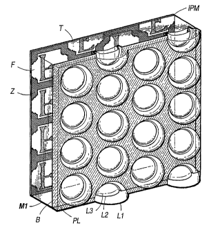
17
shows a perspective view of master array MI. In the figure, refractive effects
are ignored in
order to reveal the structural features of the array. FIG. 18A generally
illustrates the
geometry of master array Ml, and shows how M1 is assembled from outer array Al
and
inner array A2. The sectional view shown in FIG. 19A is taken along the axis
of nearest
approach of the perimeters of the discrete microlenses. This sectional axis is
indicated by
arrows in FIG. 24.
FIG. 18 shows a perspective view of display array D 1 compatible with master
arrays. FIG. 20A shows a schematic section of D1. Internal interstices in
display arrays can
optionally include prismatic diffusers PD 1 to internally distribute light. In
order to best
illustrate these prismatic interstitial reliefs, the sectional axis of FIG.
20A and 20B is at 90
to that chosen for FIGS. 19A through 19D. Al' and AT indicate outer and inner
array
components analogous to those in Ml.
In the invention, a particular hexagonal lens layout allows microimages of
various
proportions to be efficiently tiled on the focal plane. In the following
detailed discussion,
CA 02403094 2002-09-16
WO 01/71410 PCT/US01/08422
29
the microimage tiling pattern may be seen to differ from the lens tiling. The
horizontal
range can be extended using an irregular microimage profile so that a bias is
given to the
horizontal axis. The bias is sufficient to accommodate the added dimension
demanded by
binocular vision, without reduction of the vertical range, and extends the
effective viewing
field by about 10 , without introducing the aberrations that would be implicit
in a larger
lens aperture. The irregular hexagon elected also avoids the irrational
numbers implied by a
conventional hexagon and allows the use of square pixels and data blocks.
FIG l9A through FIG 19D each show first refractive boundaries L2 conformed to
the equiangular geometry described above. Figure 19A, illustrates one
embodiment of a
master array. Prior to the assembly of the Al and A2 into master array Ml,
light-blocking
cement B is applied to raised lands LD2 on A2. On assembly, LD2 meets recessed
land
LD1, forcing cement onto sidewalls SW, and leaving cement overflow BD in non-
critical
areas. Lens interstices are thus made substantially opaque.
Master array M1, in FIG 19A, was designed with particular attention to the
critical
angle 0 OA marks the optic axis of the lens cell. C is the center of curvature
of L1. Ti is an
image tile of irregular profile, which is described in detail in FIGS. 22
through 25. Points N
represent the symmetrical limits of the tile. Letter F schematically
represents any graphic
pattern within the image tile, e.g., a projected real image or a developed
photographic
emulsion.
Four specific circumstances in which the critical angle bears on array
performance,
characterized by rays Rl through R5, are shown in FIG. 19A. This reflective
effect is
represented schematically by the ray RI; all rays arriving on L2 at angles
greater than 0
will be reflected away. The total reflection will occur not just at the optic
axis, but virtually
simultaneously for all rays associated with that incident angle. The critical
angle within
polycarbonate (n=1.586) is about 39 . RI through R4 indicate the behavior of
rays which
fall outside the central focal field. Mating interstitial lands LD 1 and LD2
are formed
respectively on component arrays Al and A2, and are devised to absorb R2, R3,
and R4. In
FIGS. 19A and 19C, a circular ray terminus represents absorbed light. Ray R5
emitted from
point K beyond image field perimeter P1 is deflected by TIR at L3.
FIGS. 19B, 19C, and 19D demonstrate methods by which the system's apertures
may be reduced. Due to the relatively small size of the lenses in many
imagined
applications, the aperture-reductions methods shown may be devised to yield
diffraction-
CA 02403094 2002-09-16
WO 01/71410 PCT/US01/08422
limited performance. FIG. 19B shows a second-case master M2 array with an
internal
geometry similar to that shown in FIG. 19A, but with the aperture restricted
at L1 by dye
sublimation aperture stop SD at L1. The array of FIG. 19B would typically be
used to
convey a master image to a duplicate. Dye sublimation stop SD is created by
printing a
5 perforated lattice on a flat polycarbonate substrate and the thermoforming
the L 1 lens relief
in the material. At the glass transition temperature is obtained, the dye
sublimates locally
into the polymer. The interstitial area PL can be flat as shown. Alternately,
conic alignment
features CA can be included in the forming mold to encourage registration with
display
array D 1.
10 FIG. 19C shows third-case master array M3. M3 may be used for photographic
replication, or, reciprocally, for high-resolution viewing of transmissive
images. Stray ray
R6 is deflected by the transparent inner sidewall but is trapped by light-
blocking material B
at outer sidewall SW. Ray R7 is reflected by TIR at PL and then absorbed at
SW. Land PL
will therefore yield a dark appearance when the viewed image is observed at
extreme field
15 angles. The accessible field extended to point K, at which TIR at L2
totally occludes the
image. The viewer sees a maximum 75 field that fades, due to defocus and
diffuse
reflection, as it approaches K.
FIG. 19D shows tripartite array M4 having internal aperture screen AP. The
three
layers shown are devised to self-align and prevent decentration of the
refractive surfaces.
20 The molds for all three parts are can be devised by photoresist-based or
mechanical
processes. The imbricated packing of the L1 lenses, indicated by the absence
of an
interstitial land at Li, provides a brighter image, but an implicitly reduced
angular field. In
imbricated arrays formed of materials having refractive indices near 1.6, the
practical
attainable viewing field is about 60 .
25 FIG. 20B indicates how an L 1 aperture stop in master array M 1, here shown
with
light-blocking material B applied, allows light to be conveyed to D1 without
accessing
neighboring cells. Ray Drax designates the maximum angle at which light is
allowed to
pass from M1. This limit is set by the joint effect of the optics and the
graphic output at
master image plane IPM. An arrangement by which an efficient edge-to-edge
tiling in the
30 duplicate can be effected is shown in FIG. 24. The optical conversion from
the master to
the display array is essentially obtained by obscuring ambiguous regions of
the master
image plane and inducing a magnification factor of approximately 1.25 in the
microimages,
CA 02403094 2002-09-16
WO 01/71410 PCT/US01/08422
31
so that the images can tile seamlessly on the image plane of the duplicate
array. While this
conversion may be used to eliminate the dim peripheries of directly-recorded
integral
images, more commonly it would be implemented using master images derived from
electronically processed image data. The master image provided may therefore
be, for
example, developed transparent film, a laser scan, or a luminous display.
It is usually preferable that the lenses in the master and duplicate have a
common
pitch. However, it can be useful in the replication process to locally shift
the black graphic
lattice in the master to assign it an effectively smaller pitch than that of
the array. While
this may be obtained by scaling the entire master optical system, more
commonly it would
be introduced as an inward radial pixel shift relative the image center point.
This would
affect the composition of the microimages only in that new pixels would be
elected at some
locations, while an equal number of image pixels were blacked out at others.
The
preponderance of pixels would be unaltered, but the black lattice would me
minutely
reduced in pitch. The net effect would be that the replication process would
transpose this
inward radial shift in the master to an outward radial shift in the duplicate.
A viewer in of
the duplicate image would then observe a slightly extended angular field, as
the graphic
material could be optimized to coincide with anticipated sight-lines. In an
electronic
display, the extended field would be introduced directly in the field layout.
Materials within the invention may also used to capture full-parallax images
directly, according to the principles of integral imaging. Referring again to
FIG. 19A, it
may be understood that, at a certain refractive index, the circular microimage
perimeter PI
will be contained within the mathematical projection of the hemispheric outer
lens diameter
on the focal plane. The index at which this may be obtained, in a purely
refractive system,
is in the vicinity of n=1.7. However, the graphic surface may nevertheless be
efficiently
employed if a somewhat lower-index, inexpensive material such as polycarbonate
is used,
and microimages allowed to overlap in a conscientiously arranged null zone Z.
The null
zone in the present case resembles an irregular hexagonal lattice. Image tile
Ti is electively
limited at points N, so that all points within the image tile are unambiguous.
In integral capture and reproduction, stray light must be prevented from
passing to
adjacent lens cells through the optically open regions in the outer array. As
previously
noted, each minute optical system, consisting of a region of the planar rear
surface and a
coaxial L1, an L2, an L3 surface, is optically isolated from each other lens
cell. A TIR
effect is produced at the L3 surface with respect to any light emitted from
master
CA 02403094 2002-09-16
WO 01/71410 PCT/USO1/08422
32
microimage plane IPM. Light reaching the internal surface of L3 from any point
K beyond
a certain radius from the point where the optic axis intersects the microimage
plane is fully
reflected back toward the image plane. A pseudoscopic image, recorded on
master image
plane IPM and photographically developed, can therefore be optically
translated to display
image plane IPD, developed, and displayed as an orthoscopic integral
photograph.
Generalized photic elements PH, indicated in FIG. 23, can be construed to
denote
emulsion, discrete pixels, photodiodes, phototransistors, LEDs, liquid
crystals, plasma
cells, film recorder dots, ink dye, or toner dots, CRT triads, etc. For
clarity, the figures
show a regular orthogonal rasterization using discrete, square graphic units.
It should
nevertheless be understood that the system applies equally to continuous-tone
images.
Null photic elements PN can be disabled or eliminated. High-resolution image
capture
systems often use linear electronic arrays. A single column is shown which can
be scanned
across the width of a single microlens field to detect or emit image data. In
a capture
system, color data may be obtained by using an RGB-filtered trilinear sensor.
Linear
sensors PL may alternately be oriented on the opposite axis to that shown at
PH. Linear
sensors PL are staggered in an offset alternate manner, which can allow for
surface wiring.
A vertical scan can enable the capture of time sequences in full-parallax 3D
images,
without producing binocular conflict. If the image fields are scanned along
axis At,
temporal distortions can be masked by the display array's optical filtering.
Some
implications of this embodiment are described later in this specification.
In order for a lens-to-lens reproduction process to be effective, certain
correspondences between the arrays must be maintained. FIG. 21 shows a
schematic
sectional representation of the required optical conditions. FIGS. 22 through
25 show
schematic plan views of the respective graphic layouts of the arrays.
A master array with no light-blocking material on its first surface, such as
array M1, may
be used if a master photographic transparency at IPM is lit with a controlled
source of
illumination, so that graphic elements G may be conveyed to a conjugate image
plane. In
FIG. 21, a source's angular output is predetermined by using collimated beam
LS
that is subsequently modified by convex axiconic lens array A3 that is
oscillated in the
plane of the array during exposure. Angle 0 is given here as 32 . Assuming an
A3 having
an index of n=1.59, light is allowed to pass through the A2 portion of the M1
array only at
angles between 12.7 and 25.4 , The restricted field provides equalized
transmission across
CA 02403094 2002-09-16
WO 01/71410 PCT/US01/08422
33
the field, and excludes stray rays such as ray RX. No light is conveyed from
null zones Z,
except in the case of a negative master photographic transparency.
Alternately, a master of
the M2 type may be used with conventional sources.
In FIG. 22, gridded areas indicate null zones Z. The graphic layout of a
single
master lens cell is shown in FIG. 23. Null zones generally are not enabled to
capture or
reproduce light. In a positive-to-positive reproduction process, these areas
would be
darkened to suppress emission. If desired, an integrated photographic mask may
be
produced by the pre- or post- exposure of undeveloped film to a remote target
image laid
out in the shape of a single null zone pattern. It may be seen in FIG. 22 that
the lozenge-
shaped, overlapping intersections of lens field perimeters P 1 all fall within
the gridded null
zones. Figure F in one microimage cell is shown as it would be oriented in a
pseudoscopic
master.
Hexagon H1, associated with the imbrication of display array D1, is shown in
FIGS. 23 and 25. Hl has been derived from a square so that each side of the
hexagon is
either oriented with an orthogonal axis of the array, or has a slope that is a
ratio of integers
(1:2), rather than the irrational slope (1:1.73205...) associated with an
equilateral hexagon.
H1 has an area equal to the square of its smallest transverse dimension, and
is equal in area
to 40-pixel square S40. The abstract squares tile in an aligned manner on one
of the
orthogonal axes, and in an offset manner in the other. A master image may be
calibrated
with a regular raster grid such as RL4 in FIGS.22 and 23. 32x32 pixel square
S32 has been
defined within the larger S40 grid. Points M and N represent the dimensional
maxima of
irregular microimage tile T.
The abstract square may be readily remapped into various profiles which tile
in a
regular manner. The microimage tile pattern can be square, hexagonal, stepped,
or
cruciform, or curved, yet exactly accord with the staggered square pitch
shown. A stepped,
slightly cruciform pattern, derived from interactive viewing behaviors, is
used in the
illustrated applications. In FIG. 23, it may be seen that square S32 has been
modified by
the displacement of area AA to AB.
The arrays are configured so that the microimages undergo an optical
magnification
of 1.25 during reproduction. The same pitch is maintained between microlens
centers. A 4
dot in the master would appear as a 5 dot in the duplicate. Lens radii and
focal lengths in
the two arrays would also roughly accord with this proportion.
CA 02403094 2002-09-16
WO 01/71410 PCT/US01/08422
34
In the layout of the image cells of the display array, shown in FIG. 25,
shaded areas
AC and AD are mapped relative to hexagon HI so that displaced areas tile in
the same
proportion as tile T. It will be seen by seen by reference to FIGS. 21 through
25 that the
microimage tile T, when projected into the lens cell of a duplicate array
image plane IPD,
will tile on duplicate image plane IPD with no null areas. A region of the
display array is
shown FIG. 24. linage elements may be envisioned as having been mapped onto a
raster
lattice RL5 of 1.25 times the pitch of the master grid RL4.
FIG. 25 shows the figure F' representing the appearance of the letter "F"
after
reproduction by the method shown in FIG. 21. The figure has the proper
orientation and
chirality when viewed from the lenticulated side, indicating that the
resulting image will be
orthoscopic. The array may be oriented for maximum effect. Animations may be
extended
by aligning a tiles' longer dimension with the vertical axis; 3D images can
accommodate
eye separation by assigning the wider field to the horizontal axis.
FIGS. 26A, 26B, and 26C schematically describe the general process of
simultaneously illuminting and viewing a D 1 image having low-index
fluoropolymer
inclusions. FIG. 26A shows the optics aligned on a central point. FIG. 26B
shows a lens
cell aligned on a peripheral microimage location, associated with a viewing
angle of 30
from the optic axis, near cell limit CL. In FIG. 26C, ambient light arriving
at 60 is
conveyed diffusely to the image plane via optional prismatic reliefs. At
extreme angles, the
convergent light is diffused, and a more equal internal illumination obtained.
Ray RO may
be seen to escape through L 1.
In display arrays having air inclusions, loss of reflected ambient light
through L 1
can be significant. FIGS. 27A, 27B, and 27C schematically describe the general
process of
simultaneously illuminating and viewing display having air inclusions D2,
which has been
devised according to the earlier general discussion. The ratio of the sag
height to the
greatest clear aperture is approximately 1:4.2, and provides a viewing field
of 50 . FIG.
27A shows the on-axis performance, and 27B the array's performance near cell
limits CL.
FIG. 27C shows that at a field angle of 40 , no light is conveyed directly
through the
internal optics, but instead is either reflected by TIR or transmitted through
internal
interstices. Interstices generally transmit only the most aberrant marginal
rays. Rays
rereflected off L 1 surfaces return to the image plane, as indicated by ray
RR. In either case,
the distribution of passive illumination at the image plane is highly diffuse.
The design
CA 02403094 2002-09-16
WO 01/71410 PCT/US01/08422
shown in 27A through 27C accords with the optical geometry of Case 5 in the
above
tabular data.
Lens elements, lens systems, and lens arrays for use with the present
invention can
be manufactured using any known method of manufacture of optical devices.
Methods of
5 manufacture that have been identified as appropriate for use with this
invention include both
processes using a master from which molded replicas are created, and the
manufacturing of
individual parts by methods such as etching and reflow processes.
The formation of a master may be achieved by diamond-turning processes or
etching
processes. One or more generations of molds may be created by electroforming.
The lens
10 systems of this invention may then be created from a mold using injection-
molding,
compression molding or other molding processes.
Etching, lithographic and reflow methods of manufacture that have been
identified
as appropriate for use with this invention include photoresist reflow methods,
isotropic
etching methods, and anisotropic reactive ion etching using a grayscale mask.
Etching,
15 lithographic and reflow methods are particularly useful if lens system
within an array are
other than identical. Locally varied lenses might be used, for example, to
extend the field of
an array by altering the optical of the lens systems in a progressive manner
to target a given
object position, such as to accommodate a given viewing position.
The lens arrays for use with the present invention can be created such that
one or
20 more lens elements comprising the lens array are monolithic such that
multiple elements are
a part of single array component or discrete lens elements can be arranged to
create lens
systems, and discrete lens systems can be arranged to create lens arrays.
FIG. 28A- FIG. 28C are schematic diagrams illustrating viewing conditions of
lens
arrays. In a real scene, the lens of the eye accommodates to adjust to the
radial emission of
25 object points located at a particular distance. Because of the aberrant
optics of conventional
cylindrical or spherical arrays, the accommodative subject distance is often
somewhat
indeterminate. This circumstance is illustrated schematically in FIG. 28A, in
which VA is
an uncorrected array, PR is a radial point emission fro the graphic surface.
The resulting
ray set produced by the lens includes diverging rays analogous to those
produced by real
30 subjects, but also includes cognitively inconsistent rays such as crossing
ray RX and stray
ray RS. The set of rays RP captured by the pupil cannot be fully converged at
a point, and
instead produces an ambiguous focus at AF on retina RT, intermediate between
the near
focus AFN and the distant focus AFD. Stray rays not captured by the pupillary
diameter
CA 02403094 2002-09-16
WO 01/71410 PCT/US01/08422
36
fall into other viewing angles, reducing image contrast. Correction of
aberrations
according to the present invention allows microlenses to be configured to
generate the
diverse focal conditions described in FIG. 2A through FIG. 2B above.
The presumption of infinite conjugates yields the focal condition shown in FIG
28B. In this case, the pupil is underfilled by the output of the microlens.
The eye is focused
at infinity, but is also required to accept rays RN produced from points PX in
neighboring
microimages, generating a graphically ambiguous retinal focal spot at RFA.
A preferable condition is shown in FIG. 28C. If the lens width and the viewing
distance are
predetermined, an afocal vergence angle may be calculated that produces an
unambiguous
focus at RF. In embodiments of the invention, display optics are devised
accordingly to
produce a divergent ray set that fills the pupillary area at an anticipated
viewing distance.
The focal condition emulates a state to which the eye is well adapted, and all
rays in the
image may be brought in focus at the retina at RF without the ambiguities
inherent in both
the indeterminate focus in FIG. 28A and the underfilled state shown in FIG.
28B. Vergence
angles, being the full angular difference between outermost divergent rays VD,
are
typically under one degree.
In the general case, the vergence angle may be calculated by taking half the
pupil
radius, subtracting half the lens pitch, dividing it by the viewing distance,
taking the
inverse-sine of this quotient, and multiplying the result by two. For example,
a 300mm
viewing distance, a 4mm pupil, and a 250 spherical lens will yield a vergence
angle of
0.716 . Since the virtual focus is located at (0.125/tanO.358 )+300mm, the
display emulates
an observer-to-object distance of about 320mm. This distance is shown
schematically in
FIG. 28C as distant focus DF. An angle of 0.763 would be associated with a
field focus at
the actual image plane. The difference between 0.716 and 0.763 indicates the
degree of
astigmatism that would be present in a cylindrical array of similar pitch.
In 3D systems using refractive arrays, scene parallax and vergence angles can
depart from their natural correspondence. For example, haptic systems using
autostereoscopic electronic displays often involve the manipulation of a
simulated object in
the free space in front of a display. The parallactic attributes of this
condition are readily
simulated. However, the conventional optical design of a microlens array
induces the eye to
accommodate to points just behind the display screen. This situation
preventing a user from
concurrently focusing on hands or tools in the free space occupied by the
apparent object.
CA 02403094 2002-09-16
WO 01/71410 PCT/US01/08422
37
It may be seen by reference to FIG. 28C that a focal condition exists that
accurately
fills the pupil while producing a virtual image field ahead of the image
plane. The array
design can be modified, by shifting the image plane forward or expressly
reparameterizing
the design, to converge on an imaginary finite conjugate in the free space
ahead of the
screen, and allowing the rays to cross at near-focus point NF. In a display
having half-
millimeter microlenses designed for viewing at 500mm, distant focus DF would
be located
72mm behind the array, while near focus NF would be 62mm in front of the
array. Because
the region sampled from the graphic plane is the same as it would be if the
virtual focus
were at DF, the parallax and orientation of the 3D image are largely
unaltered. This effect
may similarly be implemented in print images to produce so-called floating
images that are
reconciled with natural vision.
Non-imaging application are within the scope of this invention. Non-imaging
applications included, but are not limited to, telecommunication systems. FIG.
2A
illustrates a focal situation having finite conjugates. A specific example of
one
embodiment of the invention, which has finite conjugates, is illustrated in
FIG. 11 and
illustrated by the tabular data of Case 4. The illustrated embodiment may be
used for
communication between remote optoelectronic devices.
It was previously noted in the main embodiment that a time-delayed line scan
does
not implicitly produce conflicts in a three-dimensional image. In microlens-
based angular
displays, animation and full-parallax do not conflict, provided the binocular
axis matches
the horizon of the array, and a predetermined viewing distance is maintained.
In
modifications of the invention, this understanding helps to free the capture
process from
conventional time constraints.
The acquisition might take 1/5 second to 1 second. A capture period of such
long
duration would often yield time distorted source images.
However, these images are never be seen by an observer. Instead, because of
the
optical filtering by the array, the temporal distortion at this rate is
normally imperceptible,
even when the viewing provisions depart from the ideal condition recited
above.
Furthermore, the scan be expressly delayed to induce a greater illusion of
animation in the
final image, as the maximum temporal step rate between rows is not
determinate. In a
digital system, each synchronous set of twenty linear scans, one per camera
module, may
be acquired independently and retained in memory. The camera may then be
returned to a
mounting to progressively collect image data over an extended period of time,
ultimately
CA 02403094 2002-09-16
WO 01/71410 PCT/US01/08422
38
producing time-lapsed, three-dimensional images representing long time
intervals. In the
final display, the time-lapse is reconstructed with a relative shift in the
vertical viewing
angle, as when a hand-held image is tilted.
In order to optimize the temporal correlation of the image, individual image
capture
fields in the camera array would need to be either radially desynchronized or
decentered.
Preferably, image fields would be decentered radially outward from the center
of the array
so that the image field centers, expressed through lens normals, would
converge at a
common point in the object field corresponding to the anticipated viewing
distance.
A particular adaptation of the time-lapse capability involves an interpolation
based on a
modified light-field function to provide highly predictive intermediate image
data. The
complete plenoptic light-field function maps the wavelength, intensity,
direction, and
temporal variation of all light passing through a volume. Because this data
set is infinite
even in finite volumes, computational implementations of the plenoptic
function consider
finite data sets sampled, by various models, from the comprehensive function.
An autostereoscopic still image need only consider certain angles within a
small
area of a single plane within a given volume. Furthermore, since source images
need not
represent real scenes, the time domain may be convolved with the spatial
domain, and one
variable eliminated. Time-distorted image sets may then be subjected to
computational
transforms that have previously been applied to sets of conventional plane
images.
Intermediate image data may be efficiently interpolated by considering the
captured grid of
images as sampled locations in a multidimensional data volume. Additionally,
known
image-based rendering systems have used approximate depth maps, extracted from
parallax
shifts in source images, to improve sharpness and to reduce mosaic artifacts
in interpolated
images. In the invention, motion and depth can be convolved as a integrated
displacement
map. The map then can be used to perform analogous function in sets of time-
shifted
source images.
In image-based three-dimensional imaging, the area captured generally
coincides
with the area displayed. If a wider field of is allowed in the capture device
than in the
display, and a light-field function is used to model the data volume,
additional views may
be extrapolated peripherally. Provided the extrapolation is relatively
constrained, only
small spatial data voids are encountered. Where encountered, these voids may
be filled, for
example, by repeating pixels, by reference to a displacement map, or by
intelligent analysis
CA 02403094 2002-09-16
WO 01/71410 PCT/US01/08422
39
of the image content. By this method, the recording device may implicitly be
made more
compact and portable.
A set of alternate tilings devised for a square-lens array, canted to 45 , are
shown in
FIGS. 29A through 32C. In some applications, such as desktop printing devices,
it is
desirable to be able to freely orient graphic images. The canted square
accommodates
arbitrary changes in format. Images with differing axial biases may optionally
be laid out
on the same document. Rectangle T2, shown in FIG. 29A, is formed in a 2:1
proportion in
order to tile in either a portrait or landscape orientation.
Hexagon T3, shown in FIG. 29B, in which a is 144 and ti is 108 , will also
tile in
such a manner. FIG. 29C shows coarsely stepped tile T4 in the horizontal
landscape
orientation, while FIG. 29D shows coarsely stepped tile T4' in the vertical
portrait position.
FIGS. 30A and 30B show the respective locations of the tiles and the lenses in
vertical and
horizontal positions. FIG. 31 shows tile T7 with a orthogonal, biaxial bias
that eliminates
some oblique views. Tiles may also vary according to their pixel resolution,
as indicated by
coarsely stepped T4 tiles in FIG. 32A, moderately stepped tiles T5 in FIG.
32B, and by
finely stepped tiles T6 in FIG. 32C.
Array M1 in FIG. 33 is shown having conic subwavelength structures AR1 and
AR2. Because the scale of the conic structures is significantly less than the
period of the
wavefronts, the structures are not resolved by the wavefronts. The gradient
undermines the
boundary effect that produces surface reflection. Optional hybrid
refractive/diffractive
surface AC is shown disposed at L2. The surface may be used according to known
principles to achromatize or athermalize the optical system. Typically, 5% of
the light
would be reflected an untreated air/polycarbonate interface. In certain
lighting conditions,
this surface reflection introduce a degree of haze to the viewed image. Image
saturation and
contrast can be enhanced by the use of a single conformal coating of a low-
index material
such as magnesium fluoride or a soluble fluoropolymer such as CYTOP (Asahi
Glass).
Subwavelength anti-reflective microstructures, such as optical slurries or
periodic "moth-
eye" relief microstructures, can provide an analogous effect. AR relief
structures are of
particular interest in the invention, as they can be produced monolithically
during molding
of the arrays, and can therefore be included at little additional cost.
Hybrid refractive/diffractive surfaces may be employed at any of the three
boundaries to reduce chromatic aberrations. Hybrid surfaces are readily
fabricated using
CA 02403094 2002-09-16
WO 01/71410 PCT/US01/08422
the anisotropic etching processes currently used to derive microoptical
reliefs. However,
the additional theoretical correction provided by the inverse dispersion of
the diffractive
component must be weighed against other introduced aberrations, imperfect
diffraction
efficiencies, increased scattering, and additional dwell time in the molding
process. Hybrid
5 surfaces can more readily be justified where the significant band was
constrained to less
than the 400nm to 700nm visible spectrum. Examples of such systems would
include
image capture systems using color-separating dichroic or mosaic filters, RGB
triad
displays, and IR, UV, or quasimonochromatic diode-laser based systems. In
these systems,
diffraction efficiencies of approaching 100% can often be obtained by the use
of
10 continuously-blazed diffractive reliefs.
An inexpensive discrete imaging device, devised according to the principles of
the
invention, is shown in FIG. 34. The device includes an electronic detector DT
located on a
substrate SB and reinforced by a mount MT. The transparent optical elements El
and E2
are designed to mechanically engage without the application of adhesive.
Centration is
15 provided by contact at D 1 and D2, while intimate contact between the
sidewalls at other
locations is physically discouraged. Because of the disposition of the air
gap, internal
reflection shunts stray light away from the detector. Light-blocking annular
aperture stop
AS of predetermined thickness in inserted within the system. the washer-like
annular stop
may be resilient to exert upward force on El so that prongs PR lock firmly at
D2.
20 Element E2 would commonly be bonded directly to the electronic component
using
an index-matched nonconductive optical cement. IP represents the image plane
of the
array. The IP surface may be located in front of the detector and equipped
with
microoptical elements such as diffractive or refractive lenses, color-
separation gratings, etc.
In these cases, a space may be left between the detector and surface IP in
order to allow a
25 distance over which the desired optical effect might be obtained. The space
may be filled
with air or a bonding material having a differing refractive index from that
of the E2
element.
The components may be formed of a material having sufficient elasticity so
that
prongs PR of element El can be made to momentarily expand to an increased
diameter.
30 Upon the application of a predetermined degree of force in alignment with
the optic axis,
prongs PR, upon contact with the conical exterior of E2, expand and then
contract to form a
mechanical connection with E2 at K1 and K2. The structure can be varied to
make the
CA 02403094 2002-09-16
WO 01/71410 PCT/US01/08422
41
connection either permanent or reversible; while four prongs are indicated in
the drawing,
the conical shell of E1 could be divided into any number of individual
sections.
Housing H may be devised of any opaque rigid material. The housing would
typically be formed so as to recess the L1 surface relative to the outer
surface of the
housing. The array design shown tolerates a degree of inconsistency in the
alignment of the
optical elements and the housing aperture. The optics in this case were
devised in
accordance with Case 3 of the recited optical geometries. The lens design is
more center-
weighted than the prior examples. At f2, the lens produces a well corrected
central image,
with lateral color being particularly well corrected. The opening in Housing H
may act as a
secondary aperture stop. Light from a scene is captured by the L1 surface and
directed
through the core optics of the array, within the predetermined angular a
range, to detector
DT. Rays R1 are reflected away by TIR as in prior embodiments. Unevenly broken
lines at
R8' and R9' indicate ray extensions that could reach the image plane. Rays R8
and R9 are
instead transmitted out of the system by inner boundary BD 1 and outer fresnel
boundary
FB. Light passing through L3 at extreme angles would be directed by internal
reflection at
optical boundary BD2 at the conic side-walls to regions of the substrate
beyond the
detector. Alternately, light may be directed out of element E2 by internal
fresnel boundary
BD2'.
A person of ordinary skill in the art will understand that applications of
aspects of
this invention are not limited to the recited embodiments. Further embodiment
include, but
are not limited to, the embodiments described below. Color filtering may be
introduced by
dyes dissipated throughout the array material, or locally by printing, dye
sublimation
transfer, or droplet deposition. For example, differing dyes may be introduced
into separate
reservoirs of the fluid UV-curing fluoropolymer. Metered amounts can then be
delivered in
a RGB or CMY pattern to the concave second surface before the arrays are
bonded,
creating an internal mosaic filter for color imaging applications.
A high-resolution monochromatic image may be obtained, and color subsequently
interpolated from a single discrete polychromatic image. In general, the
optical geometry
may be used in monochromatic, quasimonochromatic, or polychromatic systems,
and may
include radiation from beyond the visible spectrum.
Image processing can include retrospective focal correction, color and
contrast
adjustments, compression and decompression, edge enhancement, pseudoscopy
rectification, microimage displacement based on a presumed viewing distance,
view
CA 02403094 2002-09-16
WO 01/71410 PCT/US01/08422
42
interpolation, view integration and synthesis, or transposition of the
apparent location or
orientation of subjects.
Spectral bandwidth is also a design consideration when separate color channels
are
used in the reproduction process. Color photographic images may often be
produced at
higher resolutions by successive exposure light of differing wavelengths
through grayscale
spatial light modulators. The succession may be temporally or spatially
sequential. In either
case, as the optimal focal length is somewhat wavelength-dependent, some
benefit can be
obtained by matching the focal plane to the target band. In a spatial
reproduction sequence,
for example a system using three separate arrays equipped with LCD modulators
and
discrete red, green, and blue light sources, optimization may be obtained by
providing
relatively a greater overall thickness to arrays that transmit the relatively
longer
wavelengths. Alternately, a single array and modulator can be employed using
time-
sequential RGB illumination, and the focal situation modified in situ. This
adaptation can
be made by, for example, mechanically shifting the focal plane through the use
of a
piezoelectric actuator and an optical coupling fluid, or by a varifocal effect
introduced in an
index-variable liquid crystal planar reservoir under the influence of an
electrical field. For
ease of maintenance and extended durability, master arrays would commonly be
formed of
glass rather than plastic.
Arrays used as masters for face-to-face reproduction are generally optimized
by
restricted apertures to produce spots at, or just under, the Rayleigh limit.
Except at fine lens
pitches, this would permit the use of aperture plates to improve accurate
alignment and
image transfer. The aperture plate may be a discrete device installed between
the arrays
during reproduction, but would more often be permanently integrated into the
master array.
Methods of forming an aperture plate include perforation, etching, boring,
molding, tampo
printing, or dye transfer.
Regions not part of the optical corridor are generally assigned a secondary
use, such
as light absorption, diffusion, or structural support. In the systems shown,
any portion of
any internal aperture that is not accessed by rays in the active optical
pathways may be
electively and usefully abbreviated. For example, rays converged by the
aperture provided
by a hexagonal first-surface aperture, and intersecting the second refractive
surface sweep
out a delimitation on the second surface that defines a irregular rounded
polygon having,
having, due to its rotational asymmetry, a slight third-dimensional elevation.
The
intersection of the same rays set with the third surface identifies a similar
but slightly larger
CA 02403094 2002-09-16
WO 01/71410 PCT/US01/08422
43
clear aperture. In some manufacturing processes where nonrotational surfaces
are allowed,
such as reactive ion etching, these irregular geometries may electively be
implemented to
optimize the transmission characteristics of the interstices and the array's
mechanical
structure. A similar benefit may often be obtained using a best-fit elliptical
outline.
A display may include two or more planes of graphic material at differing
focal
lengths, so that an array can produce a focal output in some areas or at some
angles, and an
afocal output at others. This focal shift can produce a varied focal condition
that activates
the accommodative focusing ability of the eye. The focal planes may be in
discrete layers,
or in a monolayer that has been selectively displaced.
In further anticipated embodiments, internal lands in lens arrays may be made
slightly concave, rather than flat, so that the region is not starved of the
cement or light-
blocking material during pick-up from a roller applicator. In the case of the
fluoropolymer-
filled lenses, volumetric calculations may be performed and the surface
geometry derived,
allowing an applicator in contact with the raised lands or with the lens
vertices to deposit
metered volumes of fluid material, so that no extraneous material is expressed
when the
arrays are brought in contact.
It is well known that an optical correction may invariably be distributed over
a
larger number of surfaces. Arrays may therefore include divided layers of
lenses that mimic
the effect of the illustrated designs, without departing with the invention's
envisioned
scope. The two constituent arrays need not be monolithic to conform to the
invention. For
example, it is common practice to fabricate microlenses in thermosetting
epoxies or
acrylates upon planar substrates such as prefabricated plastic sheets or glass
windows. The
degree of freedom allowed by differing indices my be implemented without
departing from
the invention's intended scope.
Lithographic processes do not require all lenses in an array to be identical.
Locally
varied, idiosyncratically formed lenses might be used, for example, to extend
the viewing
field of a dimensional image by altering the optics of the lenses in a
progressive manner
about a given locus in order to target a presumed viewing position. In a
spherical lens
system, the center point of the image would typically include the only lens
system that was
showed true rotational symmetry.
Microlenses may include one or more conformal antireflective, antiabrasion, or
heat-resistant coatings. An array may be made so as to be displaceable in a
plane parallel
the graphic material, so that the image may be manually or automatically
scrolled to
CA 02403094 2002-09-16
WO 01/71410 PCT/US01/08422
44
provide an animated appearance. The graphic variability may be used for
naturalistic,
textural, decorative or ornamental devices or surfaces as well as imagery.
Views may be
distinguished as separate pages of text.
In addition to their embodiments as planar graphic materials, the imaging
arrays
may be mounted upon or within a functional or ornamental device such as a
watch,
watchband, bracelet, brooch, pendant, purse, belt, compact, writing
instrument, drafting
tool, lunchbox, restaurant menu, placemat, mousepad, license plate, lampshade,
nightlight,
optical data disc, drinking cup, credit card, identification card, gamepiece,
toy, sticker,
clothing accessory, or souvenir. Lens arrays may be formed as concave, convex,
or
complex surfaces; angular image data and microimage tiles may be adapted
according to
the precepts herein described.
Digital source images may include translated computational holograms. The
image
plane may be a hologram or include holographic regions. Visible data may be
derived from
invisible processes, as in radar, sonography, X-rays, electron microscopy,
nucleomagnetic
resonance (NMR), PET or CT scanning, or magnetometry. Disciplines such as
statistics,
industrial diagnostics, engineering optimizations, product design,
cartography,
seismography, meteorology, remote sensing, astronomy, medical imaging, and
molecular
modeling may generate data which is most readily appraised as a three-
dimensional or
animated representation. By enabling only on-axis viewing, arrays using the
recited
equiangular TIR geometry may be employed as privacy screens.
The scope of the invention should not therefore be construed to be limited to
the
description of the specific applications specified in this document, but
should instead be
understood to be defined by the broadest understanding permitted by the
substance of the
information recited herein, and by the fullest legal scope of the appended
claims, in which: