Note: Descriptions are shown in the official language in which they were submitted.
CA 02403197 2002-09-12
WO 01/68159 PCT/USO1/07718
INSTRUMENT AND METHOD FOR DELIVERY OF
ANAESTHETIC DRUG
BACKGROUND OF THE INVENTION
This invention relates to medical-surgical instruments and a
method of utilizing medical-surgical instruments for delivery of an
anaesthetic
drug. The invention is more particularly concerned with instruments and
methods for use in the delivery of an anaesthetic for use as a nerve block.
A nerve block may be achieved through the administration of
variable quantities of an anaesthetic agent to the plexus of a nerve. Since
the
nerve plexus is a very fragile structure, not capable of simple repair or
reconstruction, it is crucial to do as little damage as possible in locating
the
point at which the plexus may be contacted.
It has been proposed to use a needle to locate the nerve in the
usual way, and then to insert anaesthetic through the needle so that it
emerges
from the tip of the needle and contacts the nerve. An alternative procedure
involves the proper positioning of the needle and the introduction of an
epidural
catheter through the needle. Once properly placed adjacent the nerve and into
the plexus sheath of the patient, the epidural catheter may then be used to
deliver variable amounts of anaesthetic for use as a nerve block.
It has also been proposed that an integral conductive wire be
contained in the catheter, through which an electrical current may be applied
to
determine correct positioning of the catheter once it has been inserted
through
the needle. An electrical impulse sent through the conductive wire is utilized
in
determining proper placement of the tip of the catheter and, thus, the point
at
which the anaesthetic will be delivered.
Certain disadvantages exist with regard to the above referenced
methods and the apparatus available to accomplish such methods. Most
important among these is a danger associated with the uncertainty regarding
the position of the needle tip. Such uncertainty could lead to nerve damage in
manipulating the tip of the needle without knowing its position relative to
nerves in the patient's body. One reason for this uncertainty can be related
to
CA 02403197 2002-09-12
WO 01/68159 PCT/USO1/07718
_2_
leakage of electricity. Placement of the catheter can have similar
difficulties. In
addition, the integral conductive wire in the catheter can be difficult to
utilize
effectively, as it is not rigidly attached to the remainder of the catheter
apparatus. The catheter itself can also be unwieldy as it is usually of a very
small diameter.
BRIEF SUMMARY OF THE INVENTTON
In accordance with the present invention, a catheter system is
provided comprising: (a) a needle; (b) a catheter provided with an
electrically
conductive wire; and (c) a multipurpose connector provided with a structure
able to make electrical contact with the conductive wire contained in the
catheter.
The needle has a distal end and a proximal end. The distal end of
the needle terminates in a beveled aperture having a sharp tip adapted for
insertion into a nerve sheath of a patient so as to abut the nerve plexus.
Contained in the needle and co-terminus therewith at the distal end is a
removable stylet utilized in easing insertion of the needle into the patient.
The
proximal end of the needle is provided with a hub portion used for gripping
the
needle as well as for accessing the central bore of the needle. The needle,
being
of metal construction, is electrically conductive along its entire length. A
non-
conductive material may be used to coat the outer surface of the needle,
leaving
exposed portions of the proximal and distal ends of the needle, such that
electrical voltage is not expended in unnecessary places.
The catheter is adapted for insertion through the hub portion and
within and through the needle, with the distal end of the catheter capable of
protruding out of the needle's distal end. The catheter is formed primarily of
a
thermoplastic or related material which covers a tightly wound helical wire.
The helical wire extends beyond the sheath material of the catheter at both
the
proximal and distal ends thereof. The helix formed by the wire leaves the
CA 02403197 2002-09-12
WO 01/68159 PCT/USO1/07718
-3-
center of the catheter structure available as a conduit. This central conduit
of
the catheter allows fox administration of anaesthetic to the proximal end of
the
catheter.
The multipurpose connector allows the proximal end of the
catheter to be inserted therein. Once inserted therein, the multipurpose
connector may be manipulated to rigidly capture the proximal end of the
catheter. The structure of the multipurpose connector allows the proximal end
of the catheter to be accessed by a syringe or other apparatus for injecting
fluid
through the catheter. The multipurpose connector is also provided with
electrical connections which electrically contact the helical wire of the
catheter.
These electrical contacts allow the helical wire of the catheter to be
accessed
despite the presence of the multipurpose connector over the distal end of the
catheter and, thus, the protruding proximal end of the helical wire.
It is therefore an object of the present invention to provide a
needle and catheter system including components, such that the position of an
epidural needle may be identified by electrically stimulating and thus
locating a
specific nerve. When a specific nerve is located, the catheter is inserted
through
the needle to a point slightly beyond the distal tip of the needle. The
catheter
tip may then be manipulated and the optimum position for the catheter tip
determined by applying an electrical voltage through the helical wire to the
proximal tip of the helical wire, this electrical stimulation being utilized
in
locating the specific location of the catheter tip within the nerve. Once
optimum placement is achieved, the catheter is utilized for continuous
administration of anaesthetic.
Some of the objects of the invention having been stated above,
other objects will become evident as the description proceeds below, when
taken in connection with the accompanying drawings as best described below.
CA 02403197 2002-09-12
WO 01/68159 PCT/USO1/07718
-4-
BRIEF DESCRIPTION OF THE DRAWINGS
FIG. 1 is a side elevational view of the needle and stylet, with the needle
inserted into the nerve sheath;
FIG. 1A is an end-on elevational view from the distal end of the needle
structure, showing a detail of the tip of the needle, the tip of the stylet
the and
non-conductive needle material covering the region of the needle between the
proximal ends;
FIG. 1B is a side elevational view of the needle, with only a portion of the
hub
shown and the stylet removed, most of the needle being shown in section at
section line 1B-1B;
FIG. 1C is a detail of the needle tip;
FIG. 1D is a side elevational view of the inner stylet;
FIG. 2 is a side elevational view of the catheter;
FIG. 3 is an enlarged version of FIG. 2, except that the catheter sheath is
partially cut away to better show the structure of the helical wire, only
portions
of which are shown;
FIG. 4 is a side elevational view of the multipurpose connector in section,
with
the proximal end of the catheter inserted therein but not yet rigidly held in
place;
FIG. 5 is a perspective view of the metal washer, multipurpose connector wires
and sealing assembly of the multipurpose connector; and
CA 02403197 2002-09-12
WO 01/68159 PCT/USO1/07718
-5-
FIG. 6 is a side elevational view of the metal washer, multipurpose connector
wires and sealing assembly of the multipurpose connector.
DETAILED DESCRIPTION OF THE INVENTION
Referring first to FIG. 1, there is shown relevant portions of a
human body 10 containing a nerve 12 located subcutaneous to adjacent neck
portion 14. In this example of use, a needle assembly 16 has been inserted
into
a specific point in the neck 14 of the human body 10 for the purpose of
locating
the nerve 12. The needle assembly 16 comprises a needle 18 and a central
stylet 20 which extend coaxially of one another. The needle 18 is a metal
needle which is joined at its rear end to a hub 22 of a plastic material. The
needle 18 is hollow and projects about 95 mm forwardly of the hub 22.
The needle 18 has three portions along its length. The major
portion of the needle is the central portion 24 thereof. This central portion
24
of the needle is wrapped on the outside surface thereof in an insulating
coating
26 which will not conduct electricity. This coating 26 is shown in FIG. 1 as
being divided into sections of alternating color 28 and 30. Each of these
sections is of a known, specific, length. Such colored sectioning enables the
user to determine the extent of penetration of the tip 32 of the needle 18.
The remaining two portions of the needle 18 are the distal end 34
and the proximal end 36. At its proximal end 36, the needle 18 extends within
the hub 22 where it is secured, such as by molding the hub around the needle.
Between the insulating coating 26 of the central portion of the needle 24 and
the plastic hub 22 the proximal end 36 of the needle l8 is exposed such that
electrical contact with the remainder of the needle may be achieved by contact
with the exposed proximal end 36. The bore through the needle 38 opens into
an axially-aligned bore 40 through the hub 22 of the same diameter as the
needle bore 38. The rear end of the bore 42 is enlarged and tapered to provide
a
female Luer opening 44 for use in receiving the stylet 20 and stylet hub 21.
The
CA 02403197 2002-09-12
WO 01/68159 PCT/USO1/07718
-6-
hub 22 is provided with an axially-extending slot or keyway 25 formed in the
outer surface of the hub, on that side of the hub to which the tip 32 of the
needle 18 is inclined.
As shown in FIG. 1C, the forward 5 mm or so 31 of the needle 18
is bent downwardly at an angle of about 20°, the distal end 34 of the
needle
being cut such that it makes an angle 8 of about 10° with the axis of
the major
part of the needle. This inclined end of the needle provides it with a tip 32
constituting a sharp point that readily pierces body tissue. The distal end 34
of
the needle is not covered by any electrically insulating material and is in
electrical contact, by way of the covered central portion 24, with the
proximal
end 36 of the needle. The insulating coating 26 prevents the flow of
electricity
radially out of the central portion 24 of the needle, but allows the flow of
electricity axially along the length of the needle 18.
As best exemplified in FIG. 1D, the inner stylet 20 is formed of a
solid metal needle. The distal tip 45 of the stylet 20 is cut to have the same
sharp tip angle 8 as the tip 32 of the needle. Joined to the proximal end of
the
stylet 20 is a stylet hub 21 of plastic material. The stylet 20 is smaller in
diameter than the outer needle 18 and is straight along its entire length. The
connector 46 of the stylet hub 21 which grasps the stylet 20 is of generally
cylindrical shape. The forward end of the connector 46 has a Luer taper 48
that
is dimensioned to fit within the Luer-tapered opening 44 in the needle hub 22.
A short peg or key 50 of rectangular section is provided along the lower side
of
the stylet hub 21, as viewed in FIG. 1. The peg 50 extends axially of the
stylet
hub 21, being spaced outwardly by a small gap from its Luer-tapered section
48.
The peg 50 is aligned with respect to the stylet hub 21 and stylet 20 such
that,
when the peg is engaged in the slot 25 of the needle hub 22, the plane of the
inclined tip 45 of the stylet 20 lies in the same plane as the inclined tip 34
of the
needle. The combined sharp tips of the needle and stylet readily pierces body
tissue while the stylet, occupying the center bore 38 of the needle, prevents
any
tissue from entering the needle bore 38.
CA 02403197 2002-09-12
WO 01/68159 PCT/USO1/07718
_7_
Also shown in FIG. 1 is an electrical connector 52, which may be
in the form of an alligator clip which conveys electrical impulses from an
anaesthetic nerve stimulator 17 to the proximal end of the needle 36.
FIG. 1A is an end on view of the tip of the needle assembly 16,
showing the inclined tip of the needle 32 the inclined tip 45 of the stylet
20.
Also shown is the insulating coating 26. FIG. 1B is a detail of the needle 18
of
the needle assembly, with the stylet 20 removed and only showing a small
portion of the hub 22. In addition, the needle 18 of FIG. 1 has been sectioned
along section line 1B of FIG. 1A. FIG. 1B shows the relationship of the
insulating coating 26 (of exaggerated thickness) to the various portions of
the
needle 18.
Referring next to FIG. 2, there is shown a catheter assembly 54.
The catheter assembly 54 is of a diameter which allows the assembly to be
inserted through the needle assembly 16 and into the body of the patient. The
catheter assembly 54 comprising a sheath 56 formed from a thermoplastic or
similar material. A helical coil of wire 58, best shown in FIG. 3, possesses
three
portions. A proximal portion 60, a central portion 62 and a distal portion 64.
For its entire length, the helical wire 58 defines a central bore 66 through
which
a liquid may freely pass.
The central portion 60 of the helical wire 58 is completely covered
by the catheter sheath 56 and constitutes the vast majority of the total
length of
the catheter assembly 54. The proximal portion 60 of the helical wire has no
distinguishing features except that it is short relative to the central
portion of
the remainder of the catheter assembly 54 and is not covered by the catheter
sheath. The proximal portion of helical wire is left exposed so that it, and
therefore the entire wire helix 58, may be electrically contacted, as will be
discussed relative to other structures.
The distal portion 64 of the helical wire, which is also short
relative to the remainder of the catheter assembly 54 and not covered by the
catheter sheath 56, has several features associated therewith. Where the
helical
CA 02403197 2002-09-12
WO 01/68159 PCT/USO1/07718
_g_
wire 58 exits the catheter sheath 56 at the distal end thereof, the helix
maintains the tightly wound nature of the proximal 60 and central 62 portions
of the wire. This tight helix continues for a short distance along the distal
portion before the helix opens up considerably at an open helix portion 68.
The
open helix portion 68 continues for several revolutions of the helix, before
the
structure returns for the tightly wound end 70 of the distal portion 64.
Attached
to the distal end of the tightly wound end portion is a wire helix tip 72
which is
a piece of rounded metal.
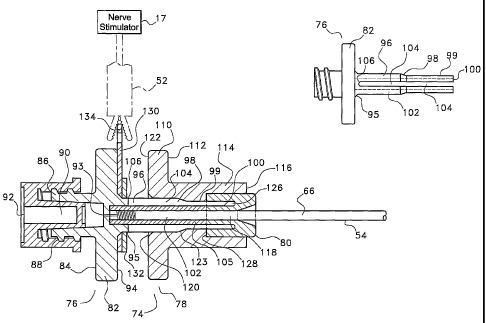
Referring next to FIG. 4, there is shown a catheter adapter 74.
Accessing the central bore 66 of the catheter assembly 54 would be nearly
impossible given the diameter of this structure. This being the case, a
catheter
adapter 74 is needed to provide access to the central bore 66 of the catheter
assembly 54 for various delivery vehicles, e.g. a syringe, for the controlled
delivery of fluid through the catheter.
The main constituents of the catheter adapter are the rear body
76, the front body 78 and the holding hub 80. The rear body 78 has a central
flange 82. From the rear face 84 of the central flange 82 extends a connection
cylinder 86 having a threaded outer surface 88 and a hollow central bore 90.
The function of this cylinder is to facilitate luer attachment of apparatus
for
controlled delivery of fluid to the catheter assembly 54. The end cap 92
provided with the catheter adapter 74 is primarily for sterility purposes, and
is
simply removed after the catheter adapter 74 is attached to the catheter
assembly 54. The central flange has, at its center, a bore 93 passing
completely
therethrough such that the rear face 84 and front face 94 are in fluid
communication.
From the front Face 94 of the central flange 84 extends an
operating cylinder 96. Where the operating cylinder 96 is connected to the
front face 94 of the central flange 84, it is of a certain diameter 95. Along
the
length of the operating cylinder, the diameter of the operating cylinder is
reduced by a taper 98. The remainder of the operating cylinder is of this
CA 02403197 2002-09-12
WO 01/68159 PCT/USO1/07718
-9-
reduced diameter 99 to the distal end 100 of the operating cylinder. The
operating cylinder 96 has a central bore 102 which extends along the entire
length thereof. Axial slots I04 extend from the distal end 100 of the
operating
cylinder, nearly the length thereof, i.e. the slot ends 106 extend nearly to
the
juncture of the operating cylinder 96 and the front face 94 of the central
flange
82. Contained in and extending most of the length of the central bore 102 of
the operating cylinder 96 is an elongated rubber gasket 105.
The front body 78 of the catheter adapter has a structure similar
in geometry to the central flange 84 of the rear body 76, this structure is
called
the rear flange 110. The rear flange 110 has extending from the front face 112
thereof a front cylinder 114. The front cylinder 114 has an essentially
constant
outside diameter extending from the front face 112 of the rear flange 110 to
the
distal end 116 of the front cylinder. A central bore 118 is provided in the
front
cylinder 114, extending the entire length thereof. This central bore 118 has
I5 several different diameter changes along its length. At the entry portion
of the
central bore 120 on the rear face I22 of the rear flange, the diameter of the
bore is slightly larger that the diameter 95 of the operating cylinder 96
where it
is connected to the front face 94 of the central flange 84. Along the length
of
the central bore 120 the inside diameter is reduced by a taper 123 which is a
mirror image of taper 98 on the operating cylinder. These mirror image
structures thus allow sliding contact between the outer surface of the
operating
cylinder 96 and the central bore 120 of the front body 78.
The holding hub 80 is a generally tubular body provided with a
cylindrical recess 126 formed in the rear face 128 thereof. The distal end 100
of
the operating cylinder 96 is matingly engageable with the cylindrical recess
128
of the holding hub 80 and is rigidly attached thereto. The diameter of the
central bore 120 of the front body 78 is, from the front face thereof 94 to a
depth less than the length of the holding hub, slightly greater than the
diameter
of the holding hub. ~ The rigid connection between the holding hub 80 and the
CA 02403197 2002-09-12
WO 01/68159 PCT/USO1/07718
-10-
distal end 100 of the operating cylinder holds these two structures in
slidable
relationship with the front body 78.
In use, the catheter adapter 74 is initially in the configuration
shown in FIG. 4. In this configuration the proximal end 57 of the catheter
assembly 54 may be freely inserted and withdrawn from the catheter adapter.
The proximal end 57 of the catheter assembly 54 may be held in place by
sliding
the front body 78 toward the rear body 76 of the catheter adapter. In sliding
these pieces relative to each other, the taper 98 of the operating cylinder 96
will
be compressed by the taper 123 of the interior of the front body. The slots
104
in the operating cylinder 96 allow this compression to occur. The compression
of the operating cylinder results in the compression of the elongated rubber
gasket 105. This compression of the elongated rubber gasket 105 results in the
rubber gasket fictionally engaging the proximal end 57 of the catheter
assembly
54 such that the catheter may not be easily removed from the catheter adapter.
An additional structure of the catheter adapter which is of interest
is the metal washer 130. This metal washer 130 is disposed about the
operating,
cylinder 96 adjacent the front face 94 of the central flange 82, and is held
in
place by nut 132. The metal washer 130 is provided with a tab portion 134
which extends above the flange portions 84 and 110. This allows electrical
contact to be made to the washer by way of the same electrical connector 52 as
was used previously.to conduct electricity into the needle assembly 16 from an
anaesthetic nerve stimulator 17. As can be seen in FIGS. 5 and 6, a pair of
wires
138 are attached to the metal washer 130 and extend from the metal washer to
the internal bore 140 of the elongated rubber gasket 105. Thus, when the
elongated rubber gasket 105 is compressed about the proximal end of the
catheter assembly 54 and about the exposed helical wire 58 found at the
proximal portion 60 thereof, electrical contact is made between the pair of
wires
138 and the helical wire 58. As a result, electrical contact may be made from
the anaesthetic nerve stimulator 17, through the catheter adapter 74 and into
CA 02403197 2002-09-12
WO 01/68159 PCT/USO1/07718
-11-
the helical wire 5~ of the catheter apparatus 54 and, thus, to the distal wire
helix tip 72 of the catheter assembly.
The above described apparatus may be used in numerous different
medical procedures. The following described medical procedure is one type
which utilizes the features embodied in the above described apparatus. The
method is drawn to the correct placement of the catheter assembly 54 and,
more particularly, the distal portion 64 thereof. Once the distal portion 64
of
the catheter assembly 54 is determined to be in the correct position, a
continuous interscalene nerve block may be administered.
The patient is positioned in the dorsal recumbent position with the
head slightly in extension and turned somewhat to the opposite side. An
assistant applies light traction on the arm with the elbow flexed.
The interscalene groove is easily palpated in this position by the
following procedure: First, the posterior edge of the clavicular head of the
sternocleidomastoid muscle is located; then the palpating fingers are placed
postern-lateral to this muscle to identify the interscalene groove. The
external
jugular vein almost always lies directly superficial to the interscalene
groove
and provides a useful additional landmark. Needle entry should be anterior or
posterior to the vein. Another constant finding is that the intersealene
groove is
approximately 3 cm lateral to the most prominent portion of the belly of the
sternocleidomastoid muscle at the level of the cricoid cartilage.
The needle assembly 16 is inserted into the interscalene groove at
the level of the cricoid (C6 level) and the needle is directed perpendicular
to the
skin in all the planes. For the placement of the catheter assembly 54 for this
continuous interscalene nerve block technique, the needle assembly 16 enters
the skin at a point approximately halfway between the mastoid and the
clavicle,
posterior to the posterior border of the clavicular head of the
sternocleidomastoid muscle.
The point of needle entry is just caudal to the accessory nerve and
just posterior to the anterior border of the posterior triangle of the neck.
The
CA 02403197 2002-09-12
WO 01/68159 PCT/USO1/07718
-I2-
accessory nerve can usually be identified by stimulating percutaneously with
the
electrical connector 52 of the nerve stimulator 17 since the nerve runs
superficial to the fascial carpet of the posterior triangle of the neck,
approximately midway between the clavicle and the mastoid. When the needle
tip 32 is proximate the accessory nerve and voltage from the nerve stimulator
17 is applied, contractions of the trapezius muscle and elevation of the
shoulder
girdle will occur. The needle assembly 16 is directed caudal and parallel to
the
vertebrae aiming for the interscalene groove with the bevel of the needle
assembly 16 directed laterally (outwards) to avoid possible central (epidural)
placement of the catheter.
During insertion of the needle assembly, voltage should be
continuously applied to the needle tip 32 as an aid in navigating the various
nerves which may be encountered. The nerves to the levator scapula and
rhomboid muscles may be encountered with the needle 32 tip at an early point.
Stimulation of these nerves will also cause movement of the shoulder girdle
when stimulated by elevating or rotating the scapula. The phrenic nerve,
situated on the belly of the anterior scalene muscle, may be encountered. This
causes unmistakable twitching of the ipsilateral diaphragm. All these nerves
should be avoided by redirection and/or reinsertion of the needle assembly 16
as stimulation of these nerves can provide false indications of correct needle
placement that will most certainly lead to block failure or phrenic nerve
paralysis if local anesthetic agent is injected at this stage.
When the brachial plexus is encountered, definite and
unmistakable muscle twitchings should be observed in the biceps and deltoid
muscles of which the biceps movements are more easily seen. This is the reason
for keeping the elbow slightly flexed during the procedure. If the phrenic
nerve
is accidentally stimulated the needle assembly 16 is pulled back slightly and
the
needle tip 32 is directed slightly posteriorly until the brachial plexus is
encountered. As the needle tip 32 is advanced further a distinct "pop" or give
can be felt followed by an increased intensity of the biceps and deltoid
muscle
CA 02403197 2002-09-12
WO 01/68159 PCT/USO1/07718
-13-
twitchings. This is when the fascia sheath of the brachial plexus is
penetrated
and the tip of the needle 32 is now in direct contact with the brachial
plexus.
The electrical connector 52 may be removed from the needle 18 at this time.
The central stylet 20 is removed from the needle 18 and the
catheter assembly 54 is fed through the needle 18 to a point just past the tip
of
the needle 32. Such a placement of the wire helix tip 72 is far enough so that
the metal helical wire 58 does not make contact with the needle, i.e. the
needle
tip 32 is in contact with the catheter sheath 56 which will not conduct
(disperse) electricity.
The catheter adapter 74 can be attached to the proximal end 60 of
the catheter assembly 54 at this point, if it has not been attached
previously.
The electrical connector 52 of the nerve stimulator 17 is then clipped to the
tab
portion 134 of the metal washer 130 provided on the catheter adapter 74.
The output of the nerve stimulator 17 can be turned down
(typically to approximately 0.5 - 1.0 mA) as the muscle twitching will
increase
because all the current is now concentrated in the unsheathed helix tip 72 of
the
catheter assembly 54. Muscle contractions with a nerve stimulator 17 output of
approximately 0.5 mA provides additional proof of proper placement into the
sheath.
. Advancement of the catheter helical tip 72 approximately an
additional 1 cm beyond the tip of the needle 32 down the brachial plexus
sheath
should not result in a decreasing of the twitching in the biceps and deltoid
muscles. Frequently, though, the muscle twitchings do decrease in which case
the needle and catheter complex 16, 54 are simultaneously pulled back slightly
as a unit, until maximal twitchings are again observed. The catheter 54 is
then
again advanced and the above process is repeated until maximal twitchings are
observed during catheter 54 advancement. It is most important for guaranteed
successful catheter placement to observe maximal muscle contractions while
catheter is being advanced. The catheter 54 frequently cannot be fed beyond
the coracoid process. It should, however, not be forced further as this may
lead
CA 02403197 2002-09-12
WO 01/68159 PCT/USO1/07718
-14-
to nerve damage and, for shoulder surgery, it is not necessary to advance the
catheter beyond this point. The needle assembly 16 may then removed and the
catheter securely fixed.
Indwelling interscalene catheters are notorious for falling out or
dislodging. To avoid dislodgment after placement of the catheter, the same
needle 16 used to place the catheter, is inserted subcutaneously from just
above
the suprasternal notch and directed superolaterally, avoiding vascular
structures, towards the point of entry of the catheter. The needle assembly 16
is
advanced to exit through the same orifice in the skin as the catheter 54 and
just
next to the catheter. The proximal end of the catheter 60 is fed from the tip
of
the needle 32 through the needle 18 and the needle is removed so that the
catheter 54 is tunneled subcutaneously.
Kinking of the catheter should be avoided as the elbow formed by
the catheter disappears under the skin. The catheter is then covered with a
transparent dressing.
With the catheter assembly thus firmly in place, anaesthetic may
be administered to effectuate a nerve block:
1. When a dense motor and sensory block is required:
a) Ropivacaine 10 mg/mL (1%). Inject 20 mL as a bolus and
then infuse with syringe driver a diluted concentration (5 mg/mL
or 0.5%) at 10 - 20 mL/hour.
Or
b) Bupivacaine 5 mg/mL (0.5%). Inject 20 mL as a bolus and
then infuse a diluted concentration (2.5 mg/mL or 0.25%) at 10 -
20 mL/hour.
CA 02403197 2002-09-12
WO 01/68159 PCT/USO1/07718
-15-
2. When sensory block with minimal motor block is required:
a) Ropivacaine 2 mg/mL (0.2%). Inject 10 - 20 mL as a bolus
and then infuse the same concentration at 1 - 10 mL/hour.
Continually adjust (titrate) the infusion rate to achieve the desired
effect.
Or
b) Bupivacaine 2.5 mg/mL (0.25%). Inject 10 - 20 mL as a
bolus and the infuse the same concentration at 1 - 10 mL/hour.
Continually adjust (citrate) the infusion rate to achieve the desired
effect.
3. Patient Controlled Interscalene Nerve Block:
Injection if a bolus of 30 mL bupivacaine (0.4%) via an indwelling
catheter into the brachial plexus sheath at the level of the
interscalene groove followed by a background infusion of
bupivacaine 0.15% at a rate of 5 mL/hour and a patient-controlled
bolus of 4 mL for patients weighing > 65 Kg and 3 mL for patients
weighing < 65 Kg. A loekout time of 20 minutes was
programmed into the PCA device. This seemed successful.
Promising preliminary results have been achieved with
ropivacaine. It seems that finer adjustment of the block to achieve
varying levels and densities of motor and sensory blockade may be
possible with ropivacaine.
While the foregoing invention has been described in some detail for
purposes of clarity and understanding, it will be appreciated by one skilled
in
CA 02403197 2002-09-12
WO 01/68159 PCT/USO1/07718
-16-
the art, from a reading of the disclosure, that various changes in form and
detail
can be made without departing from the true scope of the invention in the
appended claims.